Language selection

Search

Patent 1284619 Summary

Third-party information liability

Some of the information on this Web page has been provided by external sources. The Government of Canada is not responsible for the accuracy, reliability or currency of the information supplied by external sources. Users wishing to rely upon this information should consult directly with the source of the information. Content provided by external sources is not subject to official languages, privacy and accessibility requirements.

Claims and Abstract availability

Any discrepancies in the text and image of the Claims and Abstract are due to differing posting times. Text of the Claims and Abstract are posted:

  • At the time the application is open to public inspection;
  • At the time of issue of the patent (grant).
(12) Patent: (11) CA 1284619
(21) Application Number: 1284619
(54) English Title: PRODUCTION TIEBACK CONNECTOR
(54) French Title: TIRANT POUR COLONNE DE RACCORDEMENT D'EXTRACTION
Status: Expired and beyond the Period of Reversal
Bibliographic Data
(51) International Patent Classification (IPC):
  • F16L 37/08 (2006.01)
  • E21B 33/038 (2006.01)
(72) Inventors :
  • ABREO, WILLIAM A., JR. (United States of America)
(73) Owners :
  • COOPER CAMERON CORPORATION
(71) Applicants :
  • COOPER CAMERON CORPORATION (United States of America)
(74) Agent: SMART & BIGGAR LP
(74) Associate agent:
(45) Issued: 1991-06-04
(22) Filed Date: 1988-01-12
Availability of licence: N/A
Dedicated to the Public: N/A
(25) Language of filing: English

Patent Cooperation Treaty (PCT): No

(30) Application Priority Data:
Application No. Country/Territory Date
07/051,842 (United States of America) 1987-05-18

Abstracts

English Abstract


ABSTRACT
A subsea tieback connector including an annular body
having an external downwardly facing shoulder with high
pressure gasket type sealing means therein, a sleeve
positioned within said annular body and having means
preventing relative rotation between the sleeve and the
body, a lock ring, an actuator ring threaded into said
sleeve and having its lower end in engagement with an
internal upwardly facing shoulder on said annular body
whereby rotation of said actuating ring causes said lock
ring to be set and then tensions said sleeve to load the
connection.


Claims

Note: Claims are shown in the official language in which they were submitted.

65845-324
THE EMBODIMENTS OF THE INVENTION IN WHICH AN EXCLUSIVE
PROPERTY OR PRIVILEGE IS CLAIMED ARE DEFINED AS FOLLOWS:
1. A subsea wellhead comprising
a wellhead housing having an upper tapered seat and internal
groove below such seat,
a tieback connector having an annular body with an external
downwardly facing shoulder sized to be landed on said housing seat
and an internal upwardly facing shoulder,
a sleeve positioned within said annular body and having an
external upwardly facing shoulder, upper external threads and
means preventing rotation of said sleeve within said annular body,
a locking ring carried by said external sleeve shoulder,
said annular body having a lower end with a lower outer
tapered surface which tapers upwardly and outwardly,
an actuator ring threaded onto said sleeve external threads
and engaging said annular body internal shoulder whereby rotation
of said actuator ring raises said sleeve to raise said locking
ring into surrounding relationship to said lower annular body end
and thus wedge said locking ring outward to set said locking ring
into said housing internal groove and continued rotation of said
actuator ring tensions said sleeve to preload the engagement
between said wellhead housing seat and said body shoulder.
2. A tieback connector according to claim 1 including
sealing means carried by said body for providing a high pressure
gasket seal against a sealing surface of the wellhead housing when
said connector is secured.

6 65845-324
3. A tieback connector according to claim 1 wherein said
sealing means includes at least one groove in said exterior
shoulder of said body, and a high pressure sealing gasket
positioned within said groove.
4. A subsea wellhead according to claim 1 wherein said
rotation preventing means includes at least one pin mounted in a
slot within said annular body which extends axially therein and
having its other end secured within said sleeve.
5. A subsea wellhead according to claim 1 including means
securing said actuating ring within said annular body and against
said internal body shoulder.
6. A subsea wellhead according to claim 1 wherein said
wellhead housing seat and said external body shoulder are tapered
downwardly and inwardly, and including gasket means positioned to
provide a high pressure seal between said housing seat and said
body shoulder.

Description

Note: Descriptions are shown in the official language in which they were submitted.


~4~ 3
1 65845-324
Backaround
It is common practice in offshore oil and gas production
to have the wellhead and related casing hangers mounted at the
ocean floor with the xmas tree and other production equipment
mounted above the water level on a production platform. In such
situations tieback conductors are used to connect the subsea
wellhead equipment to the platform mounted production equipment.
In a typical application the high pressure 18 3/4 inch casing head
housing must be tied back to the production platform.
One example of a production tieback is shown in United
States Patent No. 4,343,495 wherein item 10 is a casing head
housing which is tied back to a production platform by connector
14 and conductor 12. Connector 14 is joined to housing 10 by
threaded engagement.
Another example of a tieback is disclosed in United
States Patent No. 3,497,243 wherein the conductor pipe 12 is
threaded into wellhead housing 11.
Another tieback system is shown in United States Patent
No. 4,046,405 wherein the connections include threads, latching
mechanisms and an axially threaded nut.
Summarv
The present invention provides a subsea wellhead
comprising a wellhead housing having an upper tapered seat and
internal groove below such seat, a tieback connector having an
annular body with an external downwardly facing shoulder sized to
be landed on said housing seat and an internal upwardly facing
shoulder, a sleeve positioned within said annular body and having
an external upwardly facing shoulder, upper external threads and
r~

1~f34~1.'3
la 65845-324
means preventing rotation of said sl.eeve within said annular body,
a locking ring carried by said external sleeve shoulder, said
annular body having a lower end with a lower outer tapered surface
which tapers upwardly and outwardly, an actuator ring threaded
onto said sleeve external threads and engaging said annular body
internal shoulder whereby rotation oE said actuator ring raises
said sleeve to raise said locking ring into surrounding
relationship to said lower annular body end and thus wedge said
locking ring outward to set said locking ring into said housing
internal groove and continued rotation of said actuator ring
tensions said sleeve to preload the engagement between said
wellhead housing seat and said body shoulder.

461~3
--2--
An object of the present invention is to provide an
improved tieback connector which is not threadedly at-
tached to the wellhead housing to which it is engaged.
Another object is to provide an improved tieback
05 connector which is pre-loaded when attached to the well-
head housing.
A further object is to provide an improved tieback
connector which readily accepts subsequent conductors
therein which are to be tied back.
Brief Description of the Drawinqs
These and other objects and advantages are herein-
after set forth and explained with reference to the
drawings wherein:
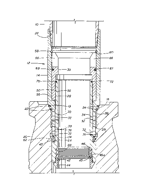
FIGURE 1 is a sectional view of the improved tieback
connector of the present invention in its unset position
within the wellhead housing to which it is to be attached.
FIGURE 2 is another sectional view of the improved
tieback connector of the present invention after it has
been attached to the wellhead housing and the connector
has been pre-loaded.
Description of the Preferred Embodiment
The normal subsea wellhead is positioned on the ocean
floor and a platform has its support structure mounted on
ocean floor around the subsea wellhead and production
equipment is positioned above water level on platform. A
tieback conductor or casing 10 extends from tieback
connector 12 to production equipment on the platform.
Tieback connector 12 includes body 14 which is
generally tubular in shape and has outer downwardly facing
shoulder 16 which is adapted to engage upwardly facing
seat 18 on wellhead housing 20. Grooves 22 in shoulder 16
are filled with high pressure gasket type seal rings 24
for sealing against seat 18. The upper interior includes
threads 26 into which tieback conductor 10 is engaged.
Tieback connector 12 also includes sleeve 28 which is

1~?34~1~<3
positioned within body 14 and actuator ring 30 which is
positioned between the upper exterior portion of sleeve 28
and the interior of body 14. Pins 32 having their
shanks 34 positioned within openings in sleeve 28 and
05 their heads 36 positioned within vertical slots 38 within
body 14 at a position below shoulder 16 as shown in FIGURE
1. The lower exterior of sleeve 28 includes upwardly
facing shoulder 40 and the lower interior of sleeve 28
includes threads 42 into which ring 44 is threaded and
buttress threads 45 thereabove with the buttress threads
45a on the exterior of split latching ring 46 engaging
the threads 45. Split latching ring 46 includes internal
threads 48 which have their lower surfaces tapering
upwardly and outwardly and their upper surfaces being
substantially normal to the axis of sleeve 28. Threads 48
are relatively fine with respect to threads 45 so that
there is limited relative rotation between split latching
ring 46 and sleeve 28. This structure provides the
support for subsequent conductor strings (not shown) to be
run and to be latched in place by ring 46 since less than
a full turn of the string is required to complete the
setting of split latching ring 46. The upper exterior of
sleeve 28 includes threads 50 into which threads 52 on the
interior of actuator ring 30 engage. Actuator ring 30
includes upper slots 66 which are engaged by a suitable
tool (not shown) for setting of the assembly as herein-
after described. Actuator ring 30 is retained within
body 14 between internal upwardly facing shoulder 56 and
snap ring 58 which is positioned within groove 60 around
the upper interior of body 14 immediately below threads
16.
Split lock ring 62 is positioned on external shoul-
der 40 of sleeve 28 and below the lower end of body 14
which is provided with external cam surface 64 which is
tapered downwardly and inwardly to coact with split lock
ring 62 during setting. Seal ring 67 is positioned in
groove 68 in the exterior of actuator ring 30 to seal

4~
--4--
between the exterior of actuator ring 30 and the interior
of body 14. Seal ring 70 is positioned in groove 72 in
the upper exterior of sleeve 28 to seal between the
exterior of sleeve 28 and the interior of actuator ring
05 30.
As shown in FIGURE 2, settlng of tieback connector 12
is achieved by rotation of actuator ring 30. The
threads 50 and 52 between sleeve 28 and actuator ring 30
causes sleeve 28 to move upwardly with respect to body 14.
This upward movement causes split loc~. ring 62 to be moved
upwardly by its engagement with shoulder 40 and such
movement causes it to be cammed outwardly by surface 64 on
the lower end of body 14 into tight engagement within
running groove 74 on the interior of wellhead housing 20.
Once lock ring 62 is set, further rotation creates a
tension in sleeve 28 which preloads the joint to ensure
tight engagement of shoulder 16 and seal rings 24 with
seat 18 on the interior upper end of wellhead housing 20.

Representative Drawing
A single figure which represents the drawing illustrating the invention.
Administrative Status

2024-08-01:As part of the Next Generation Patents (NGP) transition, the Canadian Patents Database (CPD) now contains a more detailed Event History, which replicates the Event Log of our new back-office solution.

Please note that "Inactive:" events refers to events no longer in use in our new back-office solution.

For a clearer understanding of the status of the application/patent presented on this page, the site Disclaimer , as well as the definitions for Patent , Event History , Maintenance Fee  and Payment History  should be consulted.

Event History

Description Date
Inactive: IPC from MCD 2006-03-11
Time Limit for Reversal Expired 2005-06-06
Letter Sent 2004-06-04
Grant by Issuance 1991-06-04

Abandonment History

There is no abandonment history.

Fee History

Fee Type Anniversary Year Due Date Paid Date
MF (category 1, 7th anniv.) - standard 1998-06-04 1998-05-04
MF (category 1, 8th anniv.) - standard 1999-06-04 1999-05-03
MF (category 1, 9th anniv.) - standard 2000-06-05 2000-05-03
MF (category 1, 10th anniv.) - standard 2001-06-04 2001-05-02
MF (category 1, 11th anniv.) - standard 2002-06-04 2002-05-02
MF (category 1, 12th anniv.) - standard 2003-06-04 2003-05-02
Owners on Record

Note: Records showing the ownership history in alphabetical order.

Current Owners on Record
COOPER CAMERON CORPORATION
Past Owners on Record
WILLIAM A., JR. ABREO
Past Owners that do not appear in the "Owners on Record" listing will appear in other documentation within the application.
Documents

To view selected files, please enter reCAPTCHA code :


To view images, click a link in the Document Description column (Temporarily unavailable). To download the documents, select one or more checkboxes in the first column and then click the "Download Selected in PDF format (Zip Archive)" or the "Download Selected as Single PDF" button.

List of published and non-published patent-specific documents on the CPD .

If you have any difficulty accessing content, you can call the Client Service Centre at 1-866-997-1936 or send them an e-mail at CIPO Client Service Centre.

({010=All Documents, 020=As Filed, 030=As Open to Public Inspection, 040=At Issuance, 050=Examination, 060=Incoming Correspondence, 070=Miscellaneous, 080=Outgoing Correspondence, 090=Payment})


Document
Description 
Date
(yyyy-mm-dd) 
Number of pages   Size of Image (KB) 
Claims 1993-10-19 2 53
Abstract 1993-10-19 1 13
Drawings 1993-10-19 2 52
Descriptions 1993-10-19 5 151
Representative drawing 2001-07-15 1 27
Maintenance Fee Notice 2004-08-01 1 172
Fees 1997-05-11 1 87
Fees 1995-05-17 1 102
Fees 1996-05-15 1 87
Fees 1994-03-21 1 68
Fees 1993-03-18 1 53