Language selection

Search

Patent 1284792 Summary

Third-party information liability

Some of the information on this Web page has been provided by external sources. The Government of Canada is not responsible for the accuracy, reliability or currency of the information supplied by external sources. Users wishing to rely upon this information should consult directly with the source of the information. Content provided by external sources is not subject to official languages, privacy and accessibility requirements.

Claims and Abstract availability

Any discrepancies in the text and image of the Claims and Abstract are due to differing posting times. Text of the Claims and Abstract are posted:

  • At the time the application is open to public inspection;
  • At the time of issue of the patent (grant).
(12) Patent: (11) CA 1284792
(21) Application Number: 1284792
(54) English Title: DEVICE FOR FIRMLY LOCKING A SYRINGE ON A BODY WHICH MAY BE COUPLED THERETO
(54) French Title: DISPOSITIF POUR VERROUILLER SOLIDEMENT UNE SERINGUE SUR UN OBJET
Status: Expired and beyond the Period of Reversal
Bibliographic Data
(51) International Patent Classification (IPC):
  • A61M 5/00 (2006.01)
(72) Inventors :
  • VALENTINI, LUIGI (Italy)
  • COCCIA, MARIO (Italy)
(73) Owners :
  • FARMITALIA CARLO ERBA S.R.L.
(71) Applicants :
  • FARMITALIA CARLO ERBA S.R.L. (Italy)
(74) Agent: SMART & BIGGAR LP
(74) Associate agent:
(45) Issued: 1991-06-11
(22) Filed Date: 1987-07-22
Availability of licence: N/A
Dedicated to the Public: N/A
(25) Language of filing: English

Patent Cooperation Treaty (PCT): No

(30) Application Priority Data:
Application No. Country/Territory Date
22648 B/86 (Italy) 1986-07-25

Abstracts

English Abstract


26533-6
ABSTRACT
A device is disclosed which comprises a body provided with
members for coupling it to one end of a bottle or the like and has
a seat for housing the free end of a syringe, with a hole for
allowing for the syringe needle to pass therethrough. The device
further comprises a syringe the free end of which may be housed
and threaded in said seat. On the side opposite surfaces of the
body seat and at the syringe end provided for insertion in the
seat, there are formed radially projecting longitudinal teeth and
respectively slanted resilient fins which are deflected by the
teeth as the syringe is threaded to the body and which abut against
the fins for preventing the syringe from being screwed off the
body.


Claims

Note: Claims are shown in the official language in which they were submitted.

THE EMBODIMENTS OF THE INVENTION IN WHICH AN EXCLUSIVE
PROPERTY OR PRIVILEGE IS CLAIMED ARE DEFINED AS FOLLOWS:
1. A device for transferring liquids, said device
comprising:
(a) a syringe having a working end, the working end of
said syringe having a radially inwardly facing surface and a
radially outwardly facing surface;
(b) a syringe needle projecting from the working end of
said syringe;
(c) a body having a seat sized, shaped, and positioned
to receive the working end of said syringe;
(d) said seat having a radially inwardly facing surface,
a radially outwardly facing surface, and a hole sized, shaped, and
positioned to allow said syringe needle to pass therethrough;
(e) one of said radially inwardly facing surface and
said radially outwardly facing surface of the working end of said
syringe and said radially inwardly facing surface and said
radially outwardly facing surface of said seat having threads for
coupling said syringe to said body; and
(f) the working end of said syringe and one of said
radially inwardly facing surface and said radially outwardly
facing surface of said seat having: (i) complementary and
cooperating teeth and (ii) slanted and resilient fins that permit
the threading of the working end of said syringe into said seat
but that permit the unthreading of the working end of said syringe
from said seat.

2. A device according to claim 1, wherein said body
consists of an apparatus adapted for coupling, under safe
conditions, a syringe and a drug holding bottle or the like.
3. A device according to Claim 1, wherein said body is a
cover adapted for engaging with the mouth of a drug holding bottle
or the like.
4. A device according to Claim 1, wherein said body is
provided with members for coupling to it a small tube into which
may be injected the liquid held by said syringe.

Description

Note: Descriptions are shown in the official language in which they were submitted.


~8~
The present invention relates to a device for locking,
in a firm and irreversible way, a syringe on a body to which the
syringe is coupled.
As is known, syringes are provided with a needle ~or
withdrawing from or injecting into a bottle or the like, or shap~d
end of a small sucking or discharging tube, A liquld, yenerally
provided with pharmacological properties. To that end, the syringe
may be in a free condition and freely couplea to a bottle, or it
may be mounted on an apparatus having a latching member at the
lQ bottle mouth. Such an apparatus, comprising a sealed chamber where-
in the needle is usually housed and from which the needle may exit
only when the apparatus is firmly mounted on the mouth of a bottle
or the like, is disclosed and illustrated by the United States
Patent No. 4,476,211.
For some applications and cases it may be dangerous or
undesirable to allow for the syringe to disengage from the body to
which it has been coupled. For example, it would be dangerous to
detach the syringe from the apparatus disclosed by the above
mentioned United States Patent, or remove it from the shaped end
of an intravenous injection small tube, into which a very dangerous
pharmaceutical substance, such as a cytostatic drug, may be inject-
ed by the syringe.
Thus, the main object of the present invention is to
provide such a device adapted for preventing a syringe from being
disengaged from a body to which the syringe has been coupled.
According to one aspect of the present invention there
-- 1 -
... ..... ..
,

~8479~
is provided a device for transferring liquids, said device
comprising:
(a) a syringe having a working end, the working end of
said syringe having a radially inwardly facing surface and a
radially outwardly facing surface;
(b) a syringe needle projecting from the working end of
said syringe;
(c) a body having a seat sized, shaped, and positioned
to receive the working end of said syringe;
(d) said seat having a radially inwardly facing surface,
a radially outwardly facing surface, and a hole sized, shaped, and
positioned to allow said syringe needle to pass therethrough;
(e) one of said radially inwardly facing surface and
said radially outwardly facing surface of the working end of said
syringe and said radially inwardly facing surface and said
radially outwardly facing surface of said seat having threads for
coupling said syringe to said body; and
(f) the working end of said syringe and one of said
radially inwardly facing surface and said radially outwardly
facing surface of said seat having: (i) complementary and
cooperating teeth and (ii) slanted and resilient Eins that permit
the threading of the working end of said syringe into said seat
but that permit the unthreading of the working end of said syringe
from said seat.
For better understanding the structure and
characteristics of the device according to the invention, a
preferred embodiment thereof will be disclosed thereinafter, with

~89L7~3~
reference to the accompanying drawing, where:
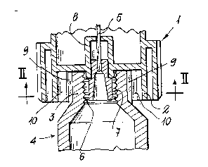
Figure 1 schematically shows an axial longitudinal
cross-section of the device, with its parts in an assembled
condition, and
Figure 2 is a cross~sec-tional view of the device, taken
along the line II-II of Figure l.
The device illustrated in the drawing comprises a body
1, which is provided with members ~which have not been shown
2a
` '

~ ` ~LZ8~
for simplicity and since they may be made in different ways) for
fixing it to the mouth of a drug holding bottle or the like. The
body has a tubular cylindrical wall 2 which defines a seat where-
in the free end 3 of a syringe 4 may be housed, with the syringe
needle 5 extending through a hole formed at the center of said
seat.
In the embodiment shown, the body 1 (an end portion of
which is shown in the drawing) consists of an apparatus like that
disclosed in ~he United States Patent 4,576,211 and adapted for
engaging, under safe conditions, a drug holding bottle to a syringe.
The needle 5 is firmly locked on the body 1 and a collar 6 pro-
jects therefrom, the free end of the syringe being engaged with
the collarvia a thread 7 formed inside the syringe free end.
It should be apparent that the body 1 may be different
from the body of the above-mentioned United States Patent. For
example, the body 1 may be provided with a tubular cylindrical wall
extending on an opposite side to the wall 2 and which may be screw
engaged on or forced onto the mouth of a bottle or the like; or
on the member 8 of the body 1 the free end of a small tube may
simply be fitted, on the other end of which an epicranial needle
may be mounted for carrying out venous transfusions.
As shown in the drawing, on the outer surface of the
syringe end 3 there is formed a tooth arrangement consisting of a
continuous plurality of teeth 9 which extend longitudinally and
the surfaces of which are slanted as shown in Figure 2.
From the inner surface of the tubular wall 2 resilient

7~3~
and slanted fins 10 project which cooperate with the keeth 9. As
should be apparent, as the syringe is threaded to the seat of the
body 1, the fins 10 will be deflected by the teeth 9, thereby
allowing for the syringe to freely rotate to be firmly coupled to
the body 1. On the other hand, if, after having coupled the
syringe to the body, one tries to~disengage ik, then the f inSr
10 (or at least some of them) will abut with their free ends again-
st the teeth 9, thereby preventing the syringe from being rotated
in an anticlockwise direction (with respect to Figure 2). In
this way the syringe will be held firmly coupled to the body 1.
It should be apparent that the teeth may be formed on
the inner surface of the tubular wall 2 and that the fins may pro-
ject from the outer surface of the syringe end to be i.nserted into
the seat of the body 1, with the same results achieved as by the
embodiment shown in the drawing.

Representative Drawing
A single figure which represents the drawing illustrating the invention.
Administrative Status

2024-08-01:As part of the Next Generation Patents (NGP) transition, the Canadian Patents Database (CPD) now contains a more detailed Event History, which replicates the Event Log of our new back-office solution.

Please note that "Inactive:" events refers to events no longer in use in our new back-office solution.

For a clearer understanding of the status of the application/patent presented on this page, the site Disclaimer , as well as the definitions for Patent , Event History , Maintenance Fee  and Payment History  should be consulted.

Event History

Description Date
Inactive: IPC expired 2023-01-01
Inactive: IPC from MCD 2006-03-11
Inactive: Adhoc Request Documented 1994-06-11
Time Limit for Reversal Expired 1993-12-13
Letter Sent 1993-06-11
Grant by Issuance 1991-06-11

Abandonment History

There is no abandonment history.

Owners on Record

Note: Records showing the ownership history in alphabetical order.

Current Owners on Record
FARMITALIA CARLO ERBA S.R.L.
Past Owners on Record
LUIGI VALENTINI
MARIO COCCIA
Past Owners that do not appear in the "Owners on Record" listing will appear in other documentation within the application.
Documents

To view selected files, please enter reCAPTCHA code :


To view images, click a link in the Document Description column. To download the documents, select one or more checkboxes in the first column and then click the "Download Selected in PDF format (Zip Archive)" or the "Download Selected as Single PDF" button.

List of published and non-published patent-specific documents on the CPD .

If you have any difficulty accessing content, you can call the Client Service Centre at 1-866-997-1936 or send them an e-mail at CIPO Client Service Centre.


Document
Description 
Date
(yyyy-mm-dd) 
Number of pages   Size of Image (KB) 
Cover Page 1993-10-20 1 13
Abstract 1993-10-20 1 19
Claims 1993-10-20 2 46
Drawings 1993-10-20 1 26
Descriptions 1993-10-20 5 138
Representative drawing 2000-07-20 1 12