Note: Descriptions are shown in the official language in which they were submitted.
Metronome
The invention relates to a metronome comprising a pendulum
which i9 fixedly mounted on a pendulum shaft for rotation
therewith; a toothed wheel shaft which is driven by a
windable spring mechanism~ a toothed wheel which is fixedly
arranged on the toothed wheel shaft for rotation therewith
and drives the pendulum by means of an anchor which i9
fixedly mounted on the pendulum shaft for rotation there-
with a bell which is struck by a bell striker; and a bell
drum which is rotatably mounted on the toothed wheel shaft
and is normally fixedly connected to the toothed wheel for
rotation therewith, to actuate the bell striker.
In such a metronome, the pendulum periodically emits audible
rhythmic beats. Depending on the set rhythm (for example, 3/4
or 4/4 rhythm) the bell is made to sound by the bell striker
at the first beat only of the selected rhythm (for example,
at each third or fourth rhythmic beat) thereby enabling clear
recognition of the first rhythmic beat of the selected rhythm
by the user of the metronome. Therefore, preoise synchroni-
.;
:' ' .
.
~1~2~S~
zation of the sounding of the bell with the pertinent rhythmicbeat is important.
In a known metronome oP the generic kind mentioned at the
beginning ~German Patent 1,810,5~6, Figures 1 and 2) the
toothed wheel and a bell drum comprised oP ~our single gear~
are pressed together by a nut to thereby enable rotation with
one another. When toothed wheel and bell drum are to be ad-
justed relative to each other in order to synchronize the
rhythmic beat with the stroke oP the bell, the nut must ~irst
be slackened and then retightened aPter the adjustment has
been made. Relative adjustment between toothed wheel and bell
drum is carried out in an inPinitely variable manner by trained
stafP.
In the known metronome, manuPacture, assembly and adjustment
of toothed wheel and bell drum involve aonsiderable ePPort
and are time-consuming and difficult. Infinitely variable
adjustability o~ the bell drum relative to the toothed wheel
may result in inaccuracies and does not enable the above
mentioned synchronization o~ bell stroke and rhythmic beat
~; to be carried out in a simple mannér.
:
The object oP the invention is to provide in a generic
metronome a simple arrangement Por synchronization o~ bell
drum and toothed wheel and to enable better checking o~
the synchronization.
In accordance with the invention, the object is achieved
by the following Peatures:
.
.
~ ~3S~l~6
a. the toothed wheel and the bell drum each aomprise
toothings facing each other, by means of which the
toothed wheel and the bell drum are in positive
engagement with each other in defined angular
positions;
b. the toothed wheel and the bell drum are axially
displaceable relative to each other on the toothed
wheel shaft in order to release their mutual positive
engagement and to alter their angular positions7
c. the toothed wheel and the bell drum are kept in mutual
positive engagement by releasable holding means.
The following description of preferred embodiments serves
in conjunction with the appended drawings to explain the
invention in further detail. In the drawings:
Figure 1 is a sectional scbematic view of a matronome
comprising pendulum, bell, toothed wheel and
bell drum;
Figure 2 is a partly broken-away illustration of bell
drum and toothed wheel;
Figure 3 is a view in the direction of arrow A in
Figure 2: and
Figure 4 is a partly broken-away illustration of a
modified embodiment.
,
.
s~
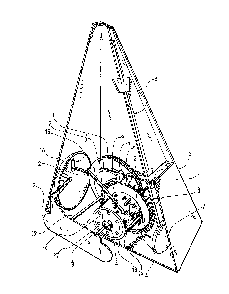
The metronome illustrated in Figure 1 comprises in the
conventional manner a pyramidal aasing 1 made, for ex-
ample, of wood. A frame 2 fixidly arranged in the in-
terior of casing 1 serves as bearing ~or the individual
parts of the metronome works.
A toothed wheel ~ is fixedly arranged on a toothed wheel
shaf~ 3 for rotation therewith. The toothed wheel shaft 3
is mounted Eor rotation in frame 2. A pendulum 8 comprising
pendulum rod 6 and pendulum weight 7 is driven in a known
manner by the toothed wheel by means of an anchor 5. Pen-
dulum rod 6 and anchor 5 are fixedly arranged on a pendulum
shaft 9 for rotation therewikh. The pendulum shaft 9 is
likewise rotatably mounted in frame 2. The toothed wheel
shaft 3 is driven in a manner likewise known per se by a
windable clockwork or spring mechanism 11 whose shaft i9
designated by reference numeral 12 in Figure 1.
Also arranged on the toothed wheel shaPt 3 is a bell drum 13
which is fixedly connected with toothed wheel 4 for rotation
therewith. Cams 14 protrude from the bell drum at specified
angular spacings. The cams cooperate in a known manner with
a bell striker lS mounted :Eor swivel motion in frame 2 in
such a way that when a cam 14 passes the free end of the bell
striker, the striker head provided on the other end always
: strikes a bell 16 mounted on frame 2. Bell striker 15 and bell
16 are displaceable in the axial direction of toothed wheel
shaft 3 (in a known and, therefore, not illustrated manner).
Hence, depending on the desired rhythm, bell striker 15 is
actuated by a specific ring of cams on bell drum 13.
. : :
.
S~4~
To enable synchronization of the rhythmic beat audibly
emitted by pendulum 8 with the striking of bell 16, it is
necessary to correspondingly adjust bell drum 13 with its
cams 14 relative to toothed wheel 4. A configuration of
toothed wheel 4 and bell drum 13 serving this purpose is
illustrated in Figures 2 and 3. The toothed wheal 4 which
is preferably made of plastic i9 fixedly arranged on the
toothed wheel shaft 3 for rotation therewith. The toothed
wheel shaft 3 is mounted for rotation on frame 2. On the
face of toothed wheel 14 facing bell drum 13, projections
17 protrude in the axial direction at equidistank angular
spacings in the form of a toothing. On the end face of bell
drum 13 opposite these projections, axially protruding pro-
jections 18 are provided at corresponding angular spacings,
likewise in the form of a toothing, and, in the operational
state of the metronome illustrated in Figure 2, positively
engage the spaces between the projections 17 on toothed
wheel 4. In this way, the toothed wheel is fixedly connected
with bell drum 13 for rotation therewith.
Spaced at approximately the axial length of bell drum 13,
opposite projections 17 on toothed wheel 4, in a rotatably,
but axially immovable manner on shaft 3 is a circular lock-
ing disk 19 having such external diameter dimensions that it
fits snugly with its external circumference into the likewise
circular inner ~ace formed by bell drum 13, thereby imparting
support and axial guidance to drum 13. The locking disk 19
which is, for example, likewise made of plastic is secured,
in the illustrated embodiment~ by claws 21 formed integrally
on disk 19 and resiliently engaging a corresponding notch in
~ .
~:~
. ' ' . ' ~ ' ~. '' ' .
~ ~85~6
- 6 -
toothed wheel shaft 3. Hence axial immovability but at the
same time rotatability of locking disk 19 relative to shaft
3 is ensured. ~he loc)cing disk 19 has slight inherent el-
asticity. It comprises at angular spacings of 90 degrees a
total of four axially extending locking recesses 22 located
in the interior of bell drum 13 and, in turn, aomprised oE
two regions 23, 24 of different depth. Region 23 - viewed
in the axial direction - i9 less deep than region 24. Axially
extending, radially inwardly oriented locking tongues 25 which
are likewise formed at angular spacings of 90 degrees on the
inside of bell drum 13 cooperate with these locking recesses
22. In the operational state illustrated in Figure 2, locking
tongues 25 engage at their ends facing locking disk 19 the
shallower regions 23 of locking recesses 22. 'rhe bell drum 13
is thereby fixed relative to locking disk 19 and to toothed
wheel 4 in such a way that the toothings on toothed wheel 4
and bell drum 13 formed by projections 17, 18 are in mutual
engagement and hence toothed wheel 4 and bell drum 13 are
in positive connection with each other.
When the locking tongues 25 are -transferred from the flat
region 23 into the deeper region 24 of the locking recesses
22 by relative rotation of locking disk 19 in relation to
bell drum 13, a certain axial play existing within region 24
with respect to locking tongue 25 permits axial displacement
of bell drum 13 relative to toothed wheel 4, thereby enabling
disengagement of projections 18 ~rom projections 17 and ro-
tation of bell drum 13 relative to toothed wheel 4. As is
apparent from Figure 2, a protuberance 26 between regions
23, 24 of lockins recesses 22 must be overcome by the
. , ' ' :
, ' ' :' '' ,
~ ~5~46
respective locking tongue 25 dur:ing relative rotation be-
tween locking disk 19 and bell drum 13. This is possible
because the elastic locking disk 19 yields somewhat as
locking tongues 25 slide over protuberance 26. ~ence
engagement of locking tongues 25 in regions 23 of re-
cesses 22 is a kind of detent or snap-in closure between
locking disk 19 and bell drum 13.
When the positive connection between toothed wheel and bell
drum 13 (similarly made of plastic) is released in the above-
described manner, the bell drum can be adjusted relative to
the toothed wheel 4 for the purpose of synchronization of
the rhythmic beat with the stroke of the bell. By subsequent
turning of locking disk 19 relative to bell drum 13, the
above-mentioned detent connection is established again,
whereby toothed wheel 4 and bell drum 13 are fixedly con-
nected again for rotation with each other in a new relative
position~
On account of the toothings provided on toothed wheel 4 and
bell drum 13 by projections 17, 18, these two parts are no
longer infinitely variably adjustable relative to each other,
but merely stepwise in accordance with the pitch spacings of
the toothings. Hence the synchronization in question can be
carried out accurately since in the event of a phase dis-
placement between the rhythmic beat and the stroke of the
bell, it is easy to indicate the specific number of pitch
spacings through which bell drum 13 must be adjusted re-
lative to toothed wheel 4.
~ . :
,' ,:
' ';
~.~ !351.~6
8 --
To transfer locking tongue 25 Erom region 23 into region 24
of locking recess 22, which requires a certain force on
account of the elastic snap-in connection, the free ~ront
face of locking disk 19 comprises apertures 27 into which
a matching tool, for example, a kind of open-end wrench can
be inserted and by means of which locking dis~ 19 can then
be turned relative to bell drum 13 to transfer locking
tongues 25 from the fla-t regions 23 into the deeper regions
24 of the locking recesses 22, which, in turn, then enable
the necessary axial displacement of the bell drum 13 relative
to the toothed wheel 4.
In the illustrated embodiment, Eour locking recésses 22 and
four locking tongues 25 are provided at corresponding angular
spacings of 90 degrees. In principle, arrangement of one single
locking recess 22 with an associated single locking tongue 25
is sufficient.
~`' .
Furthermore, in the depicted embodiment, the toothed wheel
4 is axially immovably arranged on the toothed wheel shaft
3 while the bell drum 13 is axially displaceable in relation
to the toothed wheel 4. A reverse design wherein the bell
drum 13 is fixedly arranged on the toothed wheel shaft 3 and
the toothed wheel is axially displaceable is, however, also
possible.
One of the projections 17, designated by reference numeral
28 in Figure 2, is specially designed or marked to enable
the toothed wheel 4 and the bell drum 13 to be brought into
a defined normal or initial position during final assembly
.. . .
.
.
~,lf~t~~4~
of the metronome. In the same way, one of the projections 18
is specially designed or marked. In Figure 2, this i3 indica-
ted by reference numberal 29. During final assembly, toothed
wheel 4 and bell drum 13 are connected in such a way that the
two projections 28, 29 are opposite each other, thereby pro
viding a defined initial position for a possible later ad-
justment.
In the modified embodiment shown in Figure 4, the securing
or holding means between the toothed wheel 4 and the bell
drum 13 are of different design. Arranged in an axially
immovable manner on toothed wheel shaft 3 is a dis]c 31
against which one end of a compression spring 32 arranged
in the interior of bell drum 13 is supported. The other
end of spring 32 engages a ring web 33 in the interior of
the drum 13. Thus the compression spring 32 attempts to
maintain projections 17, 18 on toothed wheel 4 and bell
drum 13, respectively, in mutual positive engagement. To
release this engagement, bell drum 13 must be pushed away
from toothed wheel 4 in the a~ial direction against the
action of spring 32, for example, by hand. After the ne-
cessary angular adjustment between toothed wheel 4 and bell
drum 13 has been madey spring 32 brings the two parts in-to
mutual positive engagement again.