Note: Descriptions are shown in the official language in which they were submitted.
~857~
1 BACXGROUND OF THE INVENTION
Field of the Invention:
The present invention relates to a plant for
manufacturing cement clinker.
Description of the Related Art:
A typical conventional plant or apparatus for
manufacturing cement clinker incorporates a combination
of a fluidized-bed type sintering furnace, a cooling
system, an air-preheater, a heat-exchanging cyclone and
a dust collector. This conventional apparatus essentially
requires the use of nuclide clinker. The nuclide clinker
is typically fine particles of clinker and is circulated
through a nuclide clinker circulating line. This
apparatus, however, suffers from disadvantages such as
a large heat loss due to circulation of the nuclide
clinker and inefficient recovery of the sensible heat
posessed by the burned clinker, resulting in a low
thermal efficiency and difficulty in the reduction of fuel
consumption.
In order to overcome these problem of the prior
art, the present inventors have already proposed, as in
Japanese Patent Publication No. 13738/1985, an apparatus
for producing cement clinker without necessitating the
use of nuclide clinker. This apparatus includes a
suspension preheater composed of a plurality of cyclones,
~L:2857S~
1 a spouted-bed granulating furnace, a fluidized-bed
type sintering furnace, a cooling apparatus and so
forth, wherein the lower portion of the spouted-bed
type granulating furnace and the upper po~tion of the
fluidized-bed type sintering furnace are connected to
each other through a waste-gas duct. More specifically,
this apparatus is characterized in that the preheated
material from the suspension preheater is charged into
the duct which interconnects the cooling system and the
spouted-bed type granulating furnace, so that the
material is mixed with the hot cooling air extracted
from the cooling system while exchanaing heat there-
between, the mixture being then fed to the sputed-bed
type granulating furnace. ~7ith this arrangement, it is
possible to eliminate problem that the molten component
of the material adheres to and grows on the inner
surface of the duct interconnecting the cooling system
and the granulating furnace so as to coat the inner
surface of the duct. In addition, it is possible to
make an efficient use of the heat collected from the
cement clinker cooling system.
In operation of the apparatus disclosed in
Japanese Unexamined Patent Publication No. 13738/1985, the
atmosphere in the spouted-bed type granulating furnace is
maintained at a liquid-phase generating temperature which
generally ranges between 1250 and 1350C. Partly because
the burner of the spouted-bed type granulating furnace in
this apparatus is provided on the straight barrel wall
~857~j~
1 of the furnace, and partly because the air suspending
the material to be calcined is introduced such as to
cover the region near the inner surface of the wall of
the granulating furnace, the fuel supplied from the
burner does not form any local hot region which would
exhibit a temperature much higher than the temperature in
the peripheral region. In consequence, a substantially
uniform temperature distribution is realized in the
spouted bed. The substantially uniform temperature
distribution, i.e., lack of a hot local region, inevitably
reduces the amount of liquid phase which is formed by
melting of the cement material powder. In consequence,
the granules formed in the granulating furnace tend to
have too small and non-uniform sizes, and the granulation
takes place only at a small rate. The generation of
the liquid phase would be increased by rising the
temperature of the spouted bed. However, in this known
apparatus, the bed temperature rises uniformly so that
the stability of the spouted bed tends to be impaired
due to agglomeration in the bed.
SU~ARY OF THE INVENTION
Accordingly, an object of the present invention
is to provide a plant which is capable of promptly and
stably producing cement clinker of large and uniform
particle sizes.
To this end, according to one aspect of the
present invention, there is provided a plant for manu-
128S76~
1 facturing cement clinker comprising: a suspensionpreheater for preheating a cement material powder; a
spouted-bed type furnace for granulating the preheated
cement material powder; a fluidized-bed type furnace
for sintering the granulated cement raw material;
a cooling system for cooling the granulated and burned
product; a plurality of burners disposed at a lower
portion of the spouted-bed type furnace so as to oppose
to one another such that their ends are directed
obliquely upward, thereby to form a local hot region
in the spouted bed; a preheated material charging chute
disposed slightly above the local hot region and adapted
for charging the preheated material powder from the
suspension preheater into the spouted-bed type furnace;
and a granulated material discharging chute provided
on one side of the local hot region.
With this arrangement, since a local hot region
is formed in the spouted bed of the spouted-bed type
granulating furnace, so that it becomes possible to stably
and efficiently produce cement clinker having uniform
and large sizes generally ranging between 2 and 3 mm. In
addition, the power consumption for grinding the clinker
can be reduced. Furthermore, since the grain size of the
cement clinker is uniform, the heat recovery efficiency
in the cooling system is remarkably improved and the
fuel consumption in the plant is appreciably decreased.
According to another aspect of the present
invention, there is provided a plant for manufacturing
~28576~
l cement clinker comprising: a suspension preheater for
preheating a cement material powder; a spouted-bed type
furnace for granulating the preheated cement material
~owder; a fluidized-bed type furnace for sintering the
granulated cement material powder; a cooling system
for cooling the granulated and burned product; a
draft tube disposed in the spouted bed in the spouted-bed
type furnace such that a gap is formed between the draft
tube and the bottom of the spouted-bed type furnace;
a burner means disposed under the draft tube so as to
cooperate with the draft tube in positively formina a
local hot region in the draft tube and moving the
granules into the draft tube through the gap; a preheated
material charging chute disposed slightly above the
local hot region and adapted for charging the preheated
material powder from the suspension preheater into the
spouted-bed type furnace; and a granulated material
discharging chute provided on one side of the local
hot region.
According to this arrangement, the combustion
gas coming into the spouted-bed type furnace is introduced
into an upper portion of the furnace through the draft
tube. The combustion gas is accompanied by the fuel,
fluidized particles and the cement material powder, so
that the fuel is burnt in the draft tube so as to form
a local hot region, whereby the cement material powder
attaches to the surface of the fluidized particles thus
promoting the granulation of the cement material powder.
~85761
l Meanwhile, the fluidized particles outside the draft tube
are cooled by the cement material and the particles recycled
from the cyclone, as well as by heat radiation. In
addition, the combustion gas does never flow towards
the conical lower portion of the spouted-bed ty2e furnace,
so that the particles in the bottom portion of the furnace
are not heated. This in turn reduces the sticking force
between the particles, thus suppressing any tendency of
agglomeration and deposition of the particles to the wall
surfaces in the conical lower portion of the furnace.
According to a third aspect of the present
invention, there is provided a plant for manufacturing
cement clinker comprising: a suspension preheater for
preheating a cement material powder; granulating and
sintering furnace for granulating and sintering the
preheated cement material powder and provided with a
spouted bed; a plurality of burners disposed in a lower
portion of said spouted-bed type furnace and adapted for
forming a local hot region in the spouted bed; a charging
chute provided slightly above the local hot region and
adapted for charging the preheated cement material powder
from the suspension preheater; and a discharge chute
disposed on one side of the local hot region and adapted
for discharging the cement raw material which has been
at least granulated.
This arrangement reduces the cost of the
apparatus for producing cement clinker, thanks to the
elimination of the fluidized-bed type furnace.
:1~85~61
1 The above and other objects and advantages of
the invention will become clear from the following
description of the preferred embodiments taken ln
conjunction with the accompanying drawings. It is to
be noted, however, the forms and arrangements of various
constituent parts of the described embodiments are only
illustrative and are not intended for limiting the scope
of the invention unless otherwise specified.
sRIEF DESCRIPTION OF THE DRAWINGS
Fig. 1 is a partly-sectioned side elevational
view of a first embodiment of an apparatus of the present
invention for producing cement clinker;
Fig. 2 is an enlarged sectional side elevational
view of an example of a spouted-bed type granulating
furnace which is incorporated in the embodiment shown in
Fig. l;
Fig. 3 is a sectional view taken along the line
III-III of Fig. 2;
Fig. 4A is a partly-sectioned side elevational
view of a second embodiment of the apparatus of the
present invention for producing cement clinker;
Fig. 4B is an enlarged sectional side elevational
view showing a modification of the fluidized calcining
furnace of the second embodiment.
Fig. 5 is a partly-sectioned side elevational
view of a third embodiment of the apparatus of the present
invention for producing cement clinker;
~Z85~6~
1 Fig. 6 is an enlarged sectional side elevational
view of a spouted-bed type granulating furnace ~hich is
incorporated in the embodiment shown in Fig. 5, as well
as an arrangement around the granulating furnace;
Figs. 7, 8 and 10 are enlarged sectional side
elevational views of modifications of the spouted-bed
type granulating furnace and portions there around in
the third embodimen-t;
Fig. 9 is a sectional view taken along the
line IX-IX of Fig. 8;
Fig. 11 is a partly-sectioned side elevational
view of fourth and fifth embodiments of the apparatus of
the invention for producing cement clinker, in which the
fourth embodiment is illustrated by solid lines while
the fifth embodiment is shown with parts illustrated by
one-dot-and-dash line in addition to the constituents of
the fourth embodiment;
Fig. 12 is an enlarged sectional side ele-
vational view of a modification of the sixth embodiment
of the apparatus of the invention for producing cement
clinker;
Fig. 13 is an enlarged sectional side elevational
view showing a portion around a spouted-bed type furnace
used in a seventh embodiment of the apparatus of the
invention for producing cement clinker;
Fig. 14 is a sectional view taken along the
line XIV-XIV of Fig. 13;
Fig. 15 is an enlarged sectional side elevational
~3576~
1 view of a modification of the embodiment shown in
Fig. 13;
Fig. 16 is a sectional view taken along the
line XVI-XVI of Fig. 15; and
Figs. 17 and 18 are schematic representation
and graph, respectively, for explaining the relation
between the bed height and the pressure drop across the
bed.
DESCRIPTION OE THE PREFERRED EMsoDIMENTs
First Embodiment
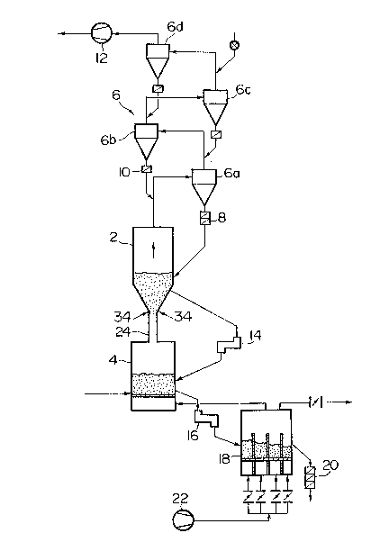
Referring to Figs. 1 to 3, cement material
powder is preheated in a suspension preheater 6 composed
of cyclones 6a, 6b, 6c and 6d by the heat of exhaust
gases from a spouted-bed type granulating furnace 2 and a
fluidized-bed type sintering furnace 4. The cement
material powder is progressively transferred through the
successive cyclones 6d, 6c, 6b and 6a and is fed into
the spouted-bed type granulating furnace 2 through a
double-flap damper 8 so as to be granulated in the
furnace 2. In these Figures, a reference numeral 10
designates a flap damper, while a numeral 12 denotes an
induced fan.
The cement material powder, which has not been
granulated in the spouted-bed type furnace 2, is recircu-
lated to the spouted-bed type granulating furnace 2
through the cyclone 6a. The particles staying in the
spouted-bed type granulating furnace and having grown
~28576~
1 therein is discharged to a fluidized-bed type sintering
furnace 4 through an L-shaped gas-tight seal device
(referred to as "L" valve, hereinafter) which makes use
of a material seal of the granulated material, so as to
be burned in the latter at a temperature between 1400
and 1500C. The thus burned cement clinker is dis-
charged, through an L valve 16 for example, to a cooling
system such as a fluidized-bed type cooler so as to be
cooled and then taken out as the final product.
On the other hand, the cooling air charged
into the cooling system 18 by a forced draft fan 22 makes
a heat exchange with the burned clinker so as to be heated
by the latter and is supplied as combustion air to the
fluidized-bed type furnace 4. Any excess air from the
cooling system 18 is discharged to the outside through
a dust collector which is not shown.
The combustion gas of the fluidized-bed
type sintering furnace 4 is used for burning the fuel
which is supplied from a burner disposed in a lower
portion of the spouted-bed type granulating furnace 2
and the gas produced as a result of the burning is
discharged as waste gas from the top of the spouted-bed
type granulating furnace 2. This gas is made to pass
through the successive cyclones 6a, 6b, 6c and 6d in the
suspension preheater 6 so as to preheat the cement
material powder, and is then exhausted to the atmosphere
by the induced fan 12 through a dust collector (not
shown). The top of the fluidized-bed type sintering
-- 10 --
lX85~76~
1 furnace 4 is connected to the bottom of the spouted-bed
type granulating furnace through a waste gas duct 24.
As will be seen from Figs. 2 and 3, the
spouted-bed type granulating furnace 2 is composed of
a stralght barrel portion 26 and a conical portion 28,
and is provided in the top end portion thereof with a
waste gas discharge duct 30 and also with a throat
portion 32 in the bottom end portion thereof. The
throat portion 32 is connected to the waste gas duct 24.
A plurality of burners, e.g. two burners as in the
illustrated embodiment, are disposed such as to oppose
to each other in a region in the vicinity of the juncture
between the conical end portion 28 and the throat
portion 32 of the spouted-bed type granulating furnace
2, such that the ends of these burners are directed
obliquely upward. With this arrangement, it is possible
to form a local hot region 38 in a portion of the
spouted bed 36 above the ends of the burners 34, the
local hot region 38 exhibiting a temperature which is
generally about 100 to 150C higher than that in the
peripheral region of the spouted bed. A preheated
material inlet chute 40 is provided slightly above the
juncture between the conical portion 28 and the straight
barrel portion 26, while a granule discharge chute 42
is disposed slightly below the juncture between the
conical portion 28 and the straight barrel portion 26.
With this arrangement, it is possible to
develop a bed temperature of about 1300 to 1400C in
~8576~
1 the spouted bed 36, by suitably selecting the velocity
of the gas ln the throat portion, while creating a high
temperature of about 1400 to 1550C in the local ho-t
region 38. As the preheated powder material of cement
is charged lnto tnis local hot region, the powder
material is quickly molten and is burned through
self-granulation while it is suspended and stagnant in
the spouted bed 36. It will be understood that the
granulation can be effected without requiring supply of
any nuclide clinker into the spouted bed 36. It is also
possible to omit the fluidized-bed type sintering furnace
4 as in the case of a fourth embodiment which will be
explained later.
The granules of the cement material thus formed
is discharged through the granule discharge chute 42
and is fed into the fluidized-bed type sintering furnace
4.
Second Embodiment:
Fig. 4 shows a second embodiment of the appa-
ratus of the present invention for producing cementclinker. As will be seen from this Figure, the fluidized
bed 44 in the fluidized-bed type sintering furnace 4 is
partitioned by a partition plate 46 into a small fluidized
bed 48 and a large fluidized bed 50. The window box 52
in this furnace also is divided by a partition plate 54
which is positioned in alignment with the first-mentioned
partition plate 46.
In operation, the granules are burned to
- 12 -
1285761
l become cement clinker at a firing temperature of about
1400 to 1500C in the large fluidized bed 50 of the
fluidized sintering furnace 4. The thus burned cement
clinker overflows the partition plate 46 into the small
fluidized-bed 48.
The small fluidized-bed chamber is maintained
at a temperature which is lower than the sintering
temperature (bed tempera~ure) in the large fluidized
bed 50. Thus, the temperature in the small fluidized bed
is, for example, about 1200 to 1000C. In consequence,
the cement clinker fired in the large fluidized bed 50
is instantaneously cooled down to the bed temperature of
the small fluidized bed 48. Thus, the fired clinker is
rapidly cooled from about 1350C down to about 1200C so
as to become cement clinker of a high quality. The cement
clinker rapidly cooled in the small fluidized bed 48 is
discharged -to the cooling system 18 through the L-valve
16 whlch serves to keep the cement clinker away from the
ambient air. The cement clinker is then further cooled
in the cooling system.
In order to rapidly cool the cement clinker
without increasing the fuel consumption, an additional
arrangement is preferably provided. This arrangement is
shown Fig. 4B and comprises an arithmetic unit 55, two
differential pressure gages 56a, 56b for measuring the
pressure drop across the small fluidized bed 48 and
across the large fluidized bed 50, respectively, and
an air-pulse injector e.g. a valve 57 for injecting
- 13 -
~.X857~
1 an air-pulse into the L-valve 16. The arithmetic unit
55 is connected to the differential pressure gage 56a
and to the differential pressure gage 56b. The arithmetic
unit 55 is also connected to the air-pulse injector 57
to operate the L-valve 16. The injector 57 injects the
air-pulse to blow the cement clinker out in the L-valve
16 so that the cement clinker in the small fluidized
bed 48 can be discharged. According to this arrangement,
the air-pulse injector 57 injects the air-pulse according
to the signal from the arithmetic unit 55 so that the
pressure drop across the small fluidized bed 48 is always
less than the pressure drop across the large fluidized
bed 50. It follows that the cement clinker can be
rapidly cooled without increasing the fuel consumption.
In order to ensure the cement clinker stabili-
zation of high quality, another additional arrangement
is preferably provided. This arrangement is also shown
in 4B and comprises an arithmetic unit 58, a thermometer
59, a motor 61 connected to the arithmetic unit 59 for
adjusting the opening of a damper 63 and a fuel valve 65
for adjusting the fuel supply to the small fluidized
bed 48. The damper 63 is one provided to the air line
between the forced draft fan 22 and the sintering furnace
4. When the temperature of the small fluidized bed 48
is higher than the predetermined temperature, the motor
61 openes the damper 63 to increase the fluidizing air
from the forced draft fan 22. To the contrary, when
the temperature of the small fluidized bed 48 is less
- 14 -
~8576~L
1 than the predetermined one, the motor 61 decreases the
opening of the damper 63 and/or the arithmetic unit 58
increase the opening of the fuel valve 65. According to
this arrangement, cooling condition in the small fluidized
bed 48 becomes constant so that the quality of the cement
clinker can be stabilized.
If there is no provision for fuel supply to
the fluidized bed, the bed temperature in the small
fluidized bed 48 is determined by the rate of supply
the hot burned cement clinker and the rate of the
fluidizing air supplied to the small fluidized bed 48.
Therefore, in the event that the yield of the cement
clinker per unit time must be decreased due to the
disturbance to the operation, the bed temperature in
the small fluidized bed 48 is lowered to decrease
the gas velocity so that the fluidity in the small
fluidized bed 48 is impaired with the result that the
cooling of the cement clinker and transfer of the same
to the L-valve 16 are impeded. In order to avoid such
a case, it is advisable to supply a small amount of fuel
into the small fluidized bed 48 so as to maintain a
temperature in the small fluidized bed 48 which is high
enough to provide the gas velocity necessary for
sufficiently fluidizing the small fluidized bed 48.
Thus, the supply fuel into the small fluidized bed 48
ensures a stable operation of the apparatus and high
quality of the cement clinker.
~2857~1
1 Third Embodiment
Referring to Figs. 5 and 6, a draft tube 62
in the form of a short pipe piece is disposed in the
spouted bed 36 in the spouted-bed type granulating
furnace 2 such that the upper end of the draft tube 62
projects slightly above the spouted bed 36 while a
small gap 64 is formed between the lower end of the draft
tube 62 and the conical portion 28 on the bottom of the
spouted-bed type granulating furnace 2. The draft tube
2 need not always project above the upper surface of the
spouted bed 36 but may completely disappear from the
same. A burner means 34 is provided in the vicinity of
the throat portion 28 under the draft tube 62 such as
to positively form a local hot region. Preferably, the
burner means 34 is composed of a plurality of burners
which are arranged to oppose one another with their ends
directed obliquely upward.
The cement material is charged into the
spouted-bed type granulating furnace through a material
charging chute 66 and/or the material charging chute 68.
The arrangement is such that, when the upper material
charging chute 66 is used, the charged material fall onto
the region near the upper end of the draft tube 62. This
arrangement effectively lowers the temperature of the
half-molten granules, thus eliminating any deposition of
the granules.
Fig. 7 shows a modification in which the draft
tube 62 is fixed by means of support members 70 and 72.
- 16 -
~8576~
1 Figs. 8 and 9 show another modification in which
cooling air is introduced into the region near the
upper end of the draft tube 62. More specifically, in
this modification, ducts 74 serving also as support
members are connected to the draft tube 62 at an upper
portion of the latter and a cooling air supply pipe 76 is
connected to these ducts 74 so as to supply cooling air
discharged from a cooler or ambient air.
Fig. lO shows still another modificatlon in
which a cooling is effected indirectly by supplying water
or air into a jacket 78 in the vicinity of the lower
conical portion 28 of the spouted-bed type granulating
furnace 2. The arrangements shown in Figs. S to 10 are
suitably combined so as to constitute the apparatus in
accordance with the third embodiment of the present
invention.
The operation of the third embodiment is as
follows. A combustion gas from the fluidized-bed type
sintering furnace 4 is introduced at a high velocity of,
for example, abou-t 30 to 50 m/sec into the spouted-bed
type granulating furnace 2 through the throat 32 on the
lower end of the latter. The gas is then introduced to
the upper part of the space in the furnace 2 through
the draft tube 62. The gas is accompanied by a fuel,
fluidized particles and the cement material powder which
are introduced through the inlet of the draft tube 62.
In consequence, the fuel is burnt in the draft tube 62
so as to form a local hot region, while the cement
- 17 -
~35'~
1 material powder attaches to the surfaces of the fluidized
particles thus promoting granulation of the cement
clinker. Meanwhile, the particles outside the draft
tube are cooled by the cement material, particles recycled
from the cyclones and through heat radiation. These
particles are not overheated because the combustion
gas does never flow into the conical portion 28. In
consequence, the sticking force acting between the
particles is decreased so as to ensure elimination of
agglomeration in the conical portion 28 further to the
first embodiment described before. At the same time,
attaching of the particles to the wall surface is avoided
for the same reason.
Fourth Embodiment:
As will be understood from Fig. 11, the fourth
embodiment of the present invention lacks the fluidized-
bed type sintering furnace 4 in the first embodiment
shown in Fig. 1. More specifically, referring to Fig. 11,
the granulated and burned product stagnant and granulated
in the spouted-bed type furnace 80 is discharged through
a discharge chute 82 which is connected to a portion
slightly below the juncture between the conical portion
28 and the barrel portion 26 of the spouted-bed type
furnace 80, by the operation of the L valve 14 which makes
use of a material seal constituted by the granulated and
burned product. The product is then delivered to a cooling
system 84 such as a fluidized-bed cooler or a moving-bed
cooler so as to be cooled in the latter.
- 18 -
1 Fifth Embodiment:
The fifth embodiment of the lnvention features,
as shown in Fig. ll, a cement material charging chute 86
connected to an upper portion of the spouted-bed type
furnace 80 for the purpose of charging at least a part
of the cement material powder. The cement material
charging chute 86 is connected such that the preheated
cement material powder from the cyclone 6b is charged
therethrough. The cement material powder charged through
this chute 86 effectively lowers the temperature of the
half-molten granules so as to prevent any sticklng of
the granules to the lnner wall surfaces ln the upper
part of the spouted-bed type furnace 80. In addltion,
since the preheated cement material powder ls decarbonized
in the upper space of the spouted-bed type furnace 80,
it is possible to maintain the required high temperature
in the local hot region 38 despite the charging of the
cement material powder into the local hot region 38
through the preheated material charging chute 40. In
consequence, it becomes possible to attain high granu-
lation and sintering speeds, while ensuring large
uniform sizes of the granulated and burned product.
Sixth Embodiment:
The sixth embodiment is basically the same as
the fourth embodiment but is distinguished from the same
in the following respects. Referring to Fig. 12, the
fourth embodiment has a jacket 88 around the upper inlet
of the granulated/burned product discharge chute 82.
-- 19 --
~28~;761
1 A multiplicity of holes 90 are Eormed in the portion
of the chute 82 within the jacket 88, and the jacket 88
is connected to a cooling air introduction pipe 92 so
that cooling air is blown into the chute 82 through the
holes 90. The cooling air introduction pipe 92 is
provided with a damper 94 which is driven by a motor 96
under the control of a computer 98. The computer 98 is
adapted for receiving a signal from a thermometer 100
adapted for detecting the temperature of the cement
clinker after the cooling. In response to this signal,
the computer 98 controls the motor 96 and, hence, the
damper 94 such as to control the flow rate of the cooling
air such that the burned cement clinker is rapidly cooled
from 1350C down to 1200C thereby ensuring high auality
of the product and ensuring that the temperature of the
cement clinker after the cooling does not exceed 1200C.
The cooling air introduction pipe 92 may be branched
from the outlet line of the forced draft fan 22 as shown
in Fig. 11.
Seventh Embodiment:
The seventh embodiment of the present invention
is basically an improvement in the conical portion of the
spouted-bed type furnace in each of the first to sixth
embodiments described hereinbefore.
Referring to Figs. 13 and 14, the lower end
portion of the spouted-bed type furnace 102 is branched
into a plurality of, e.g., three cones 28a, 28b and 28c
each having a maximum diameter smaller than the furnace
- 20 -
~ 2~35761
1 diameter, i.e., the diameter of the barrel portion 26.
Each cone is provided at the lower portion thereof with
a plurality of burners 34. In the illustrated case,
each cone is provided with two burners 34. The preheated
material powder from the cyclone 6a is charged into
these cones 28a, 28b and 28c through respective material
charging chutes 104a, 104b and 104c.
Eigs 15 and 16 show an example which is
obtained by applying the seventh embodiment to the
conical portion of the spouted-bed type furnace in the
third embodiment of the clinker apparatus of the invention.
In this example, draft tubes 62 in the form of short pipe
pieces are mounted and fixed such that gaps are formed
between their lower ends and the corresponding cones
28a, 28b and 28c in the bottom of the spouted-bed type
granulatin~ furnace 102. Burners 34 are disposed on a
lower portion of each draft tube 62.
In general, an increase in the furnace diameter
D (diameter of the barrel portion 26) of the spouted-bed
type granulating furnace causes an increase in the height
"h" of the bed as shown in Fig. 17. The pressure loss
in the furnace, i.e., the pressure drop across the bed,
is proportional to the bed height "h". Therefore, as
the furnace diameter D is increased, the pressure drop P
across the bed is increased as shown in Fig. 18. The
increase in the pressure drop P leads to an increase in
the power consumption and, hence, be avoided preferably.
In this connection, it is to be noted that the seventh
- 21 -
~8~6~
1 embodiment can suppress the increasing tendency of the
pressure loss even when the spouted-bed type furnace
is large, because the maximum diameter in the conical
portion is reduced. In addition, the cost of the
apparatus as a whole is reduced thanks to the fact
that the overall height of the spouted-bed type granu-
lating furnace is decreased as compared with the cases
of the ordinary arrangements.
- 22 -