Note: Descriptions are shown in the official language in which they were submitted.
2388-114
~ ~.Z8S768
TOY COG RAILW~Y
Back~round of the Invention
The present invention relates to toy railways and in particular to a toy cog railway.
Cog railways are used on steep slopes where static friction alone may not be
sufficient to overcome gravity. Toy cog railways have heretofore been constructed as
small scale versions of actual cog railways. Accordingly, the track for the railway has
been provided with a center rack between two rails. The associated train includes a cog
wheel that is driven by an electromotor of the train engine to engage the rack. Actual
cog railways may employ one of several systems (e.g. Riggenbach, Abt, Strub, andLocher) although toy cog railways usually employ the Strub system which utilizesupper open cogs since this simplifies the manufacture of the rack as well as the engine.
In order to make toy cog railways realistic heretofore the manufacturing costs were
relatively high and the products were not particularly robust. As a result such toys were
not particularly well suited for young children who lack technical understanding of the
toy but wish to operate the model railway over tight turns and steep slopes.
Model cog railways heretofore available also suffer from a shortcoming of actllal
cog railways in that the maximum steepness of the track slope is relatively small
particularly on tight turns. In addition, only by providing a relatively heavy engine and
a relatively light trailer load can the engille be prevented from "lifting" off the rack.
Further, model cog railway 's can only be used to a very limited extent for "pushing"
since the pushed cars tend to leave the track particularly on steep slopes and tight
turns.
In U.S. patent no. 4,547,710 there is disclosed a toy comprising a vehicle in the
form of an imaginary animal figure designed to travel on a horizontal, substantially
smooth track mounted on a support. The track is in the form of an approximate oval
1, ~
; ~85768
formed of two parallel side sections and curved end sections. The track has a vertical
cogging rack throughout its entire length on its inner edge which is engaged by a
battery driven cogwheel. The vehicle moves in one direction along the straight sections
of track and reverses direction in the curved end section. The vehicle is guided along
the track by a shoe that rides in a recess of the track between the rack and outer track
edge.
j I A toy that operates with a somewhat similar movement is also disclosed in French
i patent 517,106. This toy is also provided with a closed approximately oval track with a
vertically extending rack on the track inner face. A vehicle that moves along the track is
provided with a drive motor and a drive cog that engages the rack and which is so
constructed that that as it moves it also rotates two airplane models mounted on two
cantilevers.
In contrast two the prior art, it is an object of the present invention to provide an
model cog railway which is a realistic rnodel of actual cog railways.
A further object is to provide such an model cog railway wherein the track may
readily and easily be laid out in any desired shape without any particular skill or
expertise.
A still further objcct is to provide such an model cog railway which can operate in
both pushing and pulling modes.
S~lmmarv of the Invenhon
i The above and other beneficial objects and advantages are attained in accordance
with the present invention by providing a model cog railway comprising a model track
and model engine. The track comprises a smooth driving face on which a cog member
extends longitudinally. The cog member is provided with two transversely separated
l l l
, 2
.
~;~85768
21125-181
racks of vertically extending cogs symmetrically disposed with
respect to the drive face.
The engine is provided with a pair of guides positioned
opposite each other to engage one each of the track racks. The
engine is further provided with a drive motor having a single
drive cog wheel which is offset with respect to the center of the
separation between the guides so as to engage one or the other of
said track racks.
With the above construction a very high degree of stability
of the engine on the track is attained so that derailings on tight
curves and along winding slopes is practically eliminated even
when the engine is moving at relatively high speeds. Since the
racks extend laterally and vertically with respect to the driving
face of the track, the engagement of the cogs of the rack by the
cog wheel enables the engine to overcome steep slopes without
danger of the cog wheel disengaging from the rack. Further, the
one sided engagement of the cog wheel wlth either of the racks
facilitates mounting the engine onto the track. ~s a result of
the above, any configuration track with slopes and curves may
readily be laid out without any particular expertise.
Coupling devices are also provided between the engine and
nondriven cars to prevent such cars from derailing on steep slopes
or curves. These devices serve to apply the moving force for the
cars as close as possible to the driving face of the track and
center of gravity of the car.
The invention provides a toy cog railway system having a
train and an associated track, said track including at least one
- 3 -
1285768
21125-181
smooth driving face and a cogging member mounted along said
driving face and extending perpendicularly to said driving face,
said cogging member being provided with two teethbearing racks
transversely spaced apart from each other, said racks being
disposed symmetrically with respect to said driving face, the
longitudinal direction of the teeth of said rack extending
perpendicularly to said driving face, said at least one smooth
driving face having the form of a flat strip;
Said train including at least one vehicle in the form of an
engine car, said engine car including at least two axles each
having rimless wheels for running on said driving face, a drive
motor in driving engagement with a cogwheel that engages said
track cogging member, the rotating axis of said cogwheel extending
perpendicularly to said axles, and means for guiding said engine
car along said driving face including at least one pair of opposed
guide means formed to contact opposite sides of said cogging
member, said cogwheel being laterally displaced with respect to
the center line between said guide means so as to engage a single
one of said racks; and means :or coupling said engine car to a
further vehicle, said coupling means being attached to said engine
in the vicinity o~ ~said guide means.
The invention also provides a track for a toy cogwheel
railway, said track including at least one smooth driving face and
a cogging member mounted along said driving face and extending
perpendicularly to said driving face, said cogging member being
provided with two racks transversely spaced apart from each other,
said racks being disposed symmetrically with respect to said
driving face, the longitudinal direction of the teeth of said
- 3a -
128S7~;8
21125-181
racks extending perpendicularly to said driving face, and said at
least one smooth driving face having the form of a flat strip.
The invention still further provides an engine for a toy
cogwheel railway, said engine including at least two axles each
having rimless wheels, a drive motor in engagement with a cogwheel
for engaging a track cogging member having a pair of racks on
opposite sides thereof, the rotating axis of said cogwheel
extending perpendicularly to said axles, and means for guiding
said engine along a driving face of said track including at least
one pair of opposed guide means formed to contact sides of said
cogging member, said cogwheel being laterally displaced with
respect to the center line between said guide means so as to
engage a single one of said racks.
Brief Description of the Drawincs
In the accompanying drawings:
Fig. 1 is a side elevational view of a model train in
accordance with the present invention which is formed of building
blocks and is provided with a cog wheel;
Fig. 2 is a top plan view of the train of Fig. l;
Fig. 3 i5 a bottom plan view of the train oE Fig. l;
b ~ - 3b -
128S~6~3
i
Fig. 4 is a section of straight track for the present model cog railway;
Fig. 5 is a 'oottom plan view of the track section of Fig. 4;
Fig. 6 is a top plan view of a section of track with a 90 curve;
Fig. 7 is a bottom plan view of the ends of the track section of Fig. 6;
Fig. 8 is a bottom plan view of a flange for connecting the track sections of Figs.
4 and 6;
Fig. 9 is a bottom plan of the coupled drive chassis of Fig. 3 depicted with a rack;
Fig. 10 is a bottom plan view of of the coupled intermediary chassis of Fig. 3
depicted with a rack;
Fig. 11 is a bottom plan view of the coupled end chassis of Fig. 3 depicted with a
rack;
Fig. 12 is a perspective view of an uncoupled intermediate chassis;
Fig. 13 is a perspective view of a coupling yoke for the chassis of Fig. 12;
Fig. 14 is a top plan view of the coupling yoke of Fig. 13;
Fig. 15 is a sectional view through the coupling yoke of Fig. 13;
Fig. 16 is a perspective view of the uncoupled end chassis of Figs. 1 to 3;
Fig. 17 is a perspective view of a connecting yoke for the chassis of Fig. 16;
Fig. 18 is a top plan view of a platform for a car of the train of Figs. 1 to 3;Fig. 19 is a side elevational view of the car platform of Fig. 18;
Fig. 20 is a front elevational view of one end on the car platform of Fig. 18;
Fig. 21 is a front elevational view of the other end on the car platform of Fig. 18;
Fig. 22 Is a bottom plan view of a drive chassis in accordance with a further
embodiment of the present invention;
Fig. 23 is a side elevational view of a locomotive with two chassis;
~X857~3
ll
Fig. 24 is an enlarged side elevadonal view of the drive chassis of the locomotive
of Fig. 23;
Fig. 25 is an enlarged side elevational view of the running chassis of the
locomotive of Fig.23;
Fig. 26 is a perspective view of the drive chassis of Fig. 25;
Fig. 27 is an exploded perspective view of the drive chassis of Fig. 26;
Fig.28 is a perspective view of the running chassis of Fig. 25;
Fig. 29 is an exploded perspecdve view of the running chassis of Fig. 28;
Fig. 30 is a bottom plan view of the guiding element of the drive chassis of Fig.
27;
Fig. 31 is a bottom plan view of a mounting plate for rotating axles of the drive
chassis of Fig. 27;
Fig. 32 is a bottom plan view of the drive block of the drive chassis of Fig. 27;
Fig. 33 is a bottom plan view of the guiding element of the running chassis of
Fig. 29;
Fig. 34 is a top plan view of the platform of the enginc of Fig. 23;
Fig. 35 is A view, partially in secdon, of the model cog railway of the present
invention as a suspended railway;
Fig. 36a-36h arc sections through different embodiments of track members
provided with cog racks;
Fig. 37 is a top plan view of a section of track provided with racks in accordance
with Fig. 4 and further provided with electric current feed contacts;
Fig. 38 is a side elevational view of a metallic contact for the track section of Fig.
37; and,
S
~28S768
Fig. 39 is a front elevational view of one end of the section of
track of Fig. 37 with electrical contacts.
Detailed Description of the Preferred Embodiments
Reference is now made to the drawings and to Figs. 1-3 in particular
wherein a model train in accordance with the present invention is depic-
ted. The train is formed of building blocks and comprises a head or
control car 1, an intermediate car 2, and an end car 3. The head car 1
is connected to the intermediate car 2 through a coupling chassis 4 and
the intermediate car 2 is connected to the end car 3 through a coupling
chassis 5. The front of the head car 1 and the rear of the end car 3 are
provided with pivoted bogies 6 and 7, respectively. It should be appreci-
ated that the intermediate and end cars 2, 3 could be provided with
appropriate car bodies though a car body 8 mounted onto a platform 9 is
shown only for head car 1. Thus, if desired, walls, doors, windows, etc.
could be built from blocks onto the platforms 10, 11 of cars 2, 3. To this
end, the platforms 9, 10, 11 are provided with coupling pins 12 to which
blocks (such as those sold under the well known LEGO trademark) may be
connected The undersides of the platforms 9, 10, 11 of cars 1, 2, 3,
respectively, are hollow and reinforced with ribs 13 as shown in Fig. 3.
The chassis 4 and 5 as well as the pivoted bogies 6 and 7 are formed
of a synthetic plastic material except for the wheel axles and the coupling
or mounting elements. As shown in Fig. 3, the undersides of the pivoted
bogies 6 and 7 are generally hollow and provided with extended axle
mounting clamps 14 for receiving wheel axles 15. Each of the axles 15 is
1;~857~8
provided at its ends with a turning wheel 16, the face of which is smooth.
The pivoted bogies 6, 7 are provided with a pair of longitudinally ex-
tending opposed walls 17, 18. These walls serve as guides for the bogies
on a track provided with a rack as will be explained below. The pivoted
bogies 6, 7 are further provided with a pivot 19 (see Fig. 1) which is
fixedly positioned in a hole 20 (see Fig. 2) of the associated platform
9 or 11. Further details of this arrangement will be discussed forthwith
in connection with Figs. 16 and 17.
The underside of chassis 5 is similar to that of the pivoted bogies
6 and 7 and shown in Fig. 3. Thus, it too is provided with extended moun-
tings 14 wherein the wheel axles 15 for wheels 16 are received. In
addition, it also contains longitudinally extending opposed guide walls
21 and 22. The upper face of chassis 5 is provided with pivotal coupling
yokes 23 and 24 which pivot about lateral pins 25. The coupling yokes
23, 24 serve to detachably receive corresponding coupling elements at the
ends of platforms 10, 11. The details of the coupling means will be ex-
plained in further detail forthwith in connection with Figs. 12-15 and
Figs. 19-21. The upper face of chassis 5 is provided with coupling pins 12
to which structures may be coupled if desired.
The underside of chassis 4 is basically the same as that of chassis 5
as may be seen from Fig. 3 and includes axle mounting clamps 14, axles 15
and wheels 16 as well as guide walls 21 and 22 as previously described.
However, since chassis 4 is a driving chassis it further includes a sub-
1:~85768
stantially cylindrical electromotor 26 which is mounted in the verticalposition as shown in Figs. 1 and 2. The motor has a vertical drive axle
27 (Fig. 3) offset from the center line of the chassis which supports
a cog 28 and which preferably is driven by motor 26 via a gearing (not
shown). Cog 28 is mounted in the underside of the chassis proximal guide
wall 22. As will be described, cog 28 is designed to engage the rack of
an associated track and serves to move chassis 4 and hence the entire
train when the ~ectromotor 26 is excited. The electromotor 26 is also
provided with coupling pins 12.
The electromotor 26 is electrically fed via a plug 29 formed as a
building block along with an associated feed cable 30 to a battery
box 31 mounted in the head car 1 as shown. A slide switch 32 (Fig. 2)
controls the connection between the battery box 31 and the electromotor 26
and has "OFF", forward and reverse positions. The switch extends
1285768
slightly beyond chassis 4 and has beveled faces on its ends as shown. rnese faces may
coact with pins or the like provided on an associated track to engage the switch as the
train passes to thereby stop the train or reverse its direction. Similarly an infiared or
other type of remote control element could be provided in the head car or one of the
other cars to allow continuous control. The chassis 4 and 5 are provided with two
coupling yokes 23, 24 to permit detachable connection with the head car 1 or theplatform 10 of intermediate car 2.
The toy cog railway of the present invention further includes a track with
appropriate rack members with which the cogwheel of train engages. Preferred
embodiments of a straight section of such track is depicted in Fig. s 4 and 5. A curved
section of track is depicted in Fig. s 6 and 7. It should be realized at the outset that the
straight section of track may be of any desired length although a standard size is
preferred. The track includes on its top face two smooth longitudinally extending drive
surfaces 41 and 42 which are separated by a somewhat raised, central section 43. The
central section 43 is provided with racks 44, 45 on its opposed walls which arc
disposed vertically with respect to the drive surfaces 41, 42. Laterally extending
coupling pins 46 are provided in recessed at each end of the track section to permit
connection to another length of track by means of a coupling flange 47 as shown in
Fig. 8. The coupling flange 47 is provided with coupling pins 48 that engage the pins
46 in a clamping manner as shown in Fig. 8.
As shown in Fig. S the underside of the track section is generally hollow and
reinforced by ribs 49. A box-like opening 50 at each end of the track section permits
the section to be inserted into a base member or building plate having coupling pins in
the proper raster.
ll
1~857~8
21125-181
It can also be seen from Figure 4 that the front of
the drive surfaces 41, 42 are recessed (as at 52) or extended
(as at 51) to facilitate the coupling of two sections of track
and to relieve the stress on coupling flange 47. The
protrussion 51 and recess 52 also serve to code the track as
will be further described.
The curved track of Figure 6 is also provided with two
drive faces 53 and 54 separated by a center section 55 that is
provided with opposite racks 56 and 57. The ends of the curved
track are also provided with lateral coupling pins 46 and
protrussions 51 and recesses 52 on its end faces as described
above. As can be seen in Figure 7 the underside of the curved
section is similar to that of the straisht section and includes
the box-like cavities 50 for coupling to the appropriate pins of
a base plate. In this regard it should be noted that it is
impossible to have the circular track section exactly engage the
coupling pins of a base plate raster unless the sections extend
about 90. However, an arrangement to permit such coupling has
heretofore been disclosed in United States Patent 4,726,515.
Thus, the 90 section of track of Figure 6 may be formed of two
45 sections 59, 60 separated along line 58. Each of these
sections is composed of arcuate segment 58, 59 and a
substantially shorter straight segment 61, 62. Figure 6 also
illustrates the inner and outer radii of the track as well as
the center radius of the rack 55 which all eminate from the
displaced center point 63. Since the 45 segments 59, 61 and
--10--
.1~,,,
,`~
1285768
21125-181
60, 62 need not be identical their ends are provided with
different codings as indicated in Figure 6 at radial line 58.
The aforementioned patent application also discloses
the appropriate dimensions for sloped track segments and other
arrangements that are to be coupled to a base plate raster of
coupling pins.
-lOa-
~Z85768
Figs 9- 11 i I s~ate d~e undersidcs of cù~sis 4 and 5 and d-e pivoted bo~le 7 1=conjunction with the rack 43 of a straight section of track. It can be seen that the guide
walls 21, 22 (of chassis 4, 5) and 17, 18 (of bogie 7) contact the rack 43 on both side! ;
thereof and that the cogwheel 28 engages one side of the rack 43 only.
Fig. 12 is a perspective view of the running chassis 5 of Figs 1-3. From Figs 13-
15 it can be seen that the coupling yoke 23 has two deflected arms 65 each of which is
provided with a clamping slot 66 at its ends. The clarnping slot serves to engage the
laterally extended pins 25 of chassis 5 as shown in Fig. 1. The center part 67 of the
yoke 23 is provided with a slot 68 the inner ends of which are provided with a grooved
recess 69 (see Fig. 15). The slot 68 serves to receive a complementary tongue 70,71
mounted to the ends of the car platforms 9, 10, and 11. Thus, referring to Figs. 18-21
it can be seen that the extended tongues 70,71 at opposite ends of the platfform 10 are
provided at their outer edges with upper and lower locking buttons 72. When a tongue
70, 71 is inserted into slot 68 of the coupling yoke 23 the locking buttons push apart
the upper and lower slot walls and then pass into the grooved recess 69 so that the
tongues are locked in position. The cars may be decoupled by simply pulling the
plafform 10 off the coupling yoke 23.
It can be seen from Figs. 20 and 21 that the tongue 70 at one end of plafform 10 is
provided with a different cross-sectional shape than the tongue 71 at the opposite end 'I
of platform 10. Thus tongue 70 which is rectangular in cross-section provides a rigid
connection in slot 68 whereas tongue 71 which is rhombus-shaped permits some slight
reciprocal movement within slot 68. It has been found that if all the tongues were
shaped as tongue 70 the cars of the model train would tend to lift off the track on tight
turns particularly on steep slopes. On the other hand if all of the tongues were shaped
as tongue 71 the train cars would run unsteady at any speed. Thus it is advantageous to
1285~68
use both style tongues 70, 71 which can both be received in slot 68 of the coupling
yoke 23.
It has also been found that the force transmission engagement points between a
chassis and a car should be vertically disposed with respect to the track and the car as
those elements that part in the force transmission (i.e. the cogwheel of the drive motor
and the drive face of the track). Thus the coupling yokes 23, 24 are pivoted on the
chassis 4,5 as low as possible and as close as possible to the driving faces 41, 42.
Accordingly the lateral pins 25 of chassis 4, 5 are positioned relatively low. In
addition, the the engagement points should be as close to each other as possible in the
plane perpendicular to the longitudinal direction of the train that contains the center of
gravity of the chassis. In chassis 4 and 5 this plane is disposed in the center of the
chassis. Thus the pins 25 (Fig. 1) for coupling yokes 23,2 4 are positioned close to the chas-
8i9 centers and the coupling yokes 23, 24 are provided with unusually long inclined
arms 65 (Fig. 15) which perrrut coupling of the platforms at the ends of the chassis.
The pivot mounting of the coupling yokes 23,24 thus provides that all forces
transmitted from the chassis 4,5 to the platforms 9, 10, 11 have a main component
parallel to the track and a substantially smaller vertical component. As a result, the
moment that would tend to lift the chassis and cars off the track when the train is
operating is negligible. The cog railway is thus extremely stable even if the track is
freely suspended without support posts and laid out with steep slopes and tight curves.
The angle of inclination of the track is limited essentially only to the angle wherein the
vertical plane through the center of gravity of a chassis extends through the contact
points of the corresponding wheel axles of the wheels mounted on the track. In
practice, this corresponds to a slope of greater than 100. This is true whether the
engine is pulhng or pushing the other cars
~285768
Fig. 16 illustrates the pivoted bo~es 6, 7. In Fig. 17 a pivoting element 19 formounting the pivoted boEçLes 6,7 to the platforms 9 and 11 is illustrated. Thus, the
pivoting element 19 is provided with a cylindrical pin element 75 which is mounted on
a support yoke 76. The support yoke 76 has two arms 77 provided with clamping slots
78. Arms 77 are designed to be inserted through slots 79 of the pivoted bogLes 6, 7
and then clamped onto mounting ribs 80 of the piVOted bo~Les 6, 7 as shown in Fig. 3.
The pin element 75 is provided with a shouldel 81 through which a pair of slots 82
extend longitudinally. These slots serve to render the shoulder somewhat flexible so
that the pivoted bog~es 6,7 may be detachably but rigidly inserted into the hole 20
provided in platform 9,11 in a simple manner.
In Fig. 22 an alternative embodiment of the driven chassis 4 is depicted. In this
embodiment a pair of freely rotatable cog rollers 83 are provided opposite the drive
cogwheel 28 to absorb the pressure exerted by the drive cogwheel 28. While the
friction between the rack 43 is thus somewhat reduced with this embodiment it has the
disadvantage of being somewhat more complicated to mount onto the track because of
the cogwheels on both sides of the central section 43.
It should be understood at this point that the example of a toy cog railway train
depicted in Figs. 1-3 could rcadily be modified by using any desired combination of
chassis and pivoted bogL~g with coupled cars and platforms. A further emb~diment of
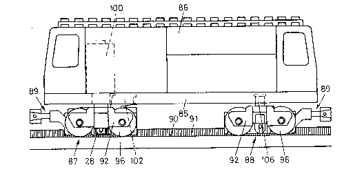
an engine is depicted in Figs 23-34. Thus, the locomotive of Fig. 23 comprises aplatform 85 to which a box-shaped cab is mounted . Two chassis 87,88 are provided
at the ends of the platform. Chassis 87 is driven and chassis 88 is free running. Both
chassis include a coupling device 89. In accordance with the present invention, the
locomotive is designed to operate on a track having on each side a smooth track face 90
13
1285768
and a center section containing a rack 91 as shown in Fig. 4. As will be described
below, both the cab and the chassis are formed of interlocked building blocks.
Figs. 24 and 25 depicted chassis 87 and 88 respectively with their wheels 96 andwheel cover plates 92 removed. The details of the components are depicted in Figs. 26-
30. Thus, the d;iven chassis 87 comprises:
a guiding and base building element 93 extending over the total length of
chassis 87, element 93 serves as a guide for the chassis and as a base for the
assembly of other building elements;
two mounting plates 94 are provided on base 93 and have openings for
receiving wheel axles 95 on which wheels 96 are mounted, the wheels have
smooth running faces for riding on the smooth driving faces 90 of the
associated track,
a drive unit 97 mounted on mounting plates 94 which is provided with
longitudinal plate parts 98, side plate parts 99, and an electromotor lO0. The
drive axle of the motor is provided with the drive cogwheel 28 designed to
engage one of the racks 91 of the track center section;
two support yokes 101 are mounted to the drive unit 97 and the elements 93 to
thereby hold together the elements 93, mounting plates 94 and drive unit 97 as astruct~al unit;
a connecting yoke pivoted on the base element 92 and used to rotatably connect
the chassis 87 and the platform 85; and,
coupling device 89 which contains a coupling yoke 103 pivoted to element 93
and arranged to couple the locomotive to another car.
14
~2857~8
The nondriven chassis 88 (Fig. 25) is constructed in a sirnilar fashion as the driven
chassis and consists of the following elements:
a guiding and base element 104 corresponding to element 93;two mounting
plates 94 are provided on base 93 and have openings for receiving wheel axles
95 on which wheels 96 are mounted, the wheels have smooth running faces for
riding on the smooth driving faces 90 of the associated track;two support yokes
105 that hold together the elements 104 and mounting plates 94; a central pivot
pin element 106 mounted on the element 104 and designed to be rotatably
disposed in platforrn 85 of the locomotive; and, coupling device 89 which is
pivoted on the element 104 and includes coupling yoke 93.
As previously discussed, the base building element 93 is provided on its upper
face with an arrangement of coupling pins for the block building system and on its
lower face with extended slide guiding walls 107, 108 and an intermediate space 109
designed to receive the central track section 91 as shown in Fig. 30. One longitudinal
side of element 93 is provided with a recess 110 to receive the drive cogwheel 28. Both
sides are provided with extended mounting pins llla, lllb, lllc and Illd and
protrussion 112 as shown in Figs. 30 and 33.
Referring back to Fig. 24, the connecdng yoke 102 and the coupling yoke 103 of
the coupling device 89 are pivoted on element 93. To this end, the connecting yoke is
provided with arms 113 each containing a clamping slot 114 which permit the arms to
be attached to the inner mounting pins 11 lc. The yoke section is provided with a slot-
like opening 115 provided with pin 116. The connecting yoke is used to pivotally
1~85'768
connect the chassis 87 and platform 85 of the locomotive as depicted in Fig. 23.Rotation in the vertical direction is limited by the protrussions 112 which abut arms
113.
Coupling yoke 103 of device 89 is similar to yoke 102 and is provided with arms
117, 118 each having a hole 119 at their ends which permit the yoke to be inserted on
the outer mounting pins 11 la as shown in Fig. 24. Again vertical movement is limited
by the extensions 120 of arms 117, 118 abuthng protrussions 112.
The yoke portion of coupling yoke 103 is also provided with a slot like opening
121 provided with a pin 122. The opening and pin 122 receive a clamping flange 123
of yoke 124. Yoke 24 has two arms 125 each having a hole 126. A magnet support
127 including a permanent magnet 128 is secured by mounting pins 129 in holes 126.
The pins permit the magnet support 127 to rotate between the arms 125 of yoke 124 so
that the north pole of the magnet may be positioned opposite the south pole of the
magnet of a sirnilar coupling device to provide a magnetic coupling of the vehicles
carrying the coupling yokes.
Referring to Fig. 27 it can be seen that coupling pins 12 of the base element 93 are
used to connect the base to two mounting plates 94 which each contain clamping
openings 131 for a wheel axle (not shown) . As shown in Fig. 31 the underside ofmounting plates 94 further include a groove-like recess 132 for the axle and a central
extended tube 133 designed to counter couple with the coupling pins 12 of the block
elements in a known fashion. The mounting plates 94 are also provided with coupling
pins 12 on the upper face.
Referring to Fig. 26 it can be seen that the wheels 96 are mounted on the axles so
as to ùe posihor ~1 laterally outwe~t11y of theit asso ia~eo conne hng yoke 102,103.
16
l ll
1 ~28S768
Drive unit 97 is mounted to mounting plates 94 as shown in Fig. 24 with
mounting plate parts 98, side plates 99 and the vertically extending motor 10. The outer
faces of plate parts 98 and 99 are provided with coupling pins in the standard array.
The undersides of plate parts 98 are similar to that of the mounting plates 94 except for
the absence of the axle mountings. As can be seen, the drive cogwheel 28 of motor lOO
extends between the side plates 99 so that the cogwheel is positioned in the recess 110
of element 93 (see Fig. 30). A pin 134 is provided in each of the side pla~es 99movable in the longitudinal direction. The pins may be used to actuate switchingelements (not shown) for controlling the current to the motor 100. As a result, by i
providing protrussions along the track to engage the pins control of the motor may be
effected to alter the direction of or stop the train.
Two support yokes 101 (see Fig. 24) are provided to hold the various elements
together. The support yoke 101 may be connected to coupling pins 12 of the
longitudinal plate parts 98 of the drive unit 97 and are locked onto the remaining pins
11 lb and 11 lc of element 93 by means of slots 13~ provided in arms 135. Cover plate
92 is provided on each side of the assembly inserted into coupling pins 12 of the side
plate 99 of drive unit 97.
The constn~ction of the nondriven chassis of Figs. 23 and 25 are depicted in detail
in Figs. 28 and 29. Thus, the n~nnillg chassis 88 is provided with guiding and base
element lO, the underside of which is shown in Fig. 33 and is substantially similar to
that of the driven chassis except that it does not include a recess for receiving the
cogwheel but Instead has a continuation of the longitudinal sidewalls and an additional
mounting pin llle. As can be seen in Figs. 25, 28 and 29 coupling device 89 is
pivotally mounted on element 104 through holes 119 of the coupling yoke 103 and
~7
1 1285768
mounting pins llld as already described. Coupling yoke 103 includes yoke 124,
magnet support 127 and permanent magnet 128.
In place of the drive unit 97, the running chassis 88 is provided with a pivot
mounting device 138 which includes a a pivot pin 139 provided with an upper shoulder
140 and includes longitudinal slots within the shoulder. Two downwardly directedextended flanges 142 (only one of which can be seen in Fig. 29) are provided at their
ends with a slot 143 and flanges extend laterally from the tops of flanges 142 and each
contain a coupling pin 12 on an upper face as shown. The pivot pin 138 is only slightly
movable when mounted on base 104 by virtue of the flange slots engaging center
mounting pins 11 le. The wheel cover plates (Fig. 29) are mounted to the coupling pins
12 of the pivot mounting means 138.
As shown in Fig. 34, the upper face of platforrn 85 is provided coupling pins 12in a standard array for receiving blocks to form a car or a battery box for the motor.
The platform is further provided with an opening 145 into which a flange 146 extends.
The flange 146 is provided with a clamping slot 147 at its free end. The motor 100 is
fed through opening 145 for mounting the chassis 87 onto platform 85. Slot 115 of
connecting yoke 102 is applied to flange 146 until its clamping slot 147 locks on pin
166 (Fig. 27) of the connecting yoke 102. In this manner the chassis 87 is pivotally
mounted onto platfoml 85. The center bore 148 perrnits rotation of the running chassis
88 with regard to platfomn 85. To this end, the pivot pin 139 of chassis 88 is inserted
into this bore and retained by shoulder 140.
From Figs.24 and 25 it can be seen that the various force transmitting elements of
the present cog railway, narnely the connecting yoke 102 and the coupling device 89 on
mountin~ pins la-llld are pivoted very close to the center ot ~ravity-t ansverse
~,
1 lxas76s
plane on chassis 87 and 88 respectively to provide for great stability of the train up to
the tilt limit.
The toy cog railway of the present invention may utilize tracks mounted on the
ground7 on ramps or suspended as shown in Fig. 35. Referring to Fig. 35 it can be
seen that the track consists of a series of track sections 150 having generally box-like
profiles open at their bottom face. The track sections are supported by posts 152 to
support the track a desired height above the ground 151. Track piece 150 is provided
with two legs 154 which a separated to define a lower opening 153. Yoke 155 is
disposed opposite the opening with sides 156 connecting to yke 155 and the legs
154. The inner faces of the legs 154 provide driving faces for the wheels 96 of a
vehicle 157. Acenterrack member 158 is provlded on the inner face of yoke 155.
Vehicle 157 ( which, in the exemplified embodiment comprises an engine) is
provided with a driven chassis 159 similar to chassis 87 of Figs. 26 and 27 modified to
permit it to be suspended and therefore requiring a different coupling means. Thus, the
chassis 159 is provided with the base element 93, mounting plates 94, wheels 96, drive
unit 97, electromotor 100, side plates 99, control pins 134, coupling yoke 67 with
arms 65 and a slot 68 for receiving tongue 71 of the coupled platform of a car as
depicted in Fig. 35 and as previously described. ~n electromotor lO0 has a driving axle ',
extending vertically upwardly toward the inner face of yoke 155 supports a cogwheel
(not shown ) which is in contact with one of the racks of the center cogging member
158. Thus, it should be appreciated that the suspended railway of Fig. 35 operates as
the train of Fig. 1 or Fig. 23. Since the wheels 96 of vehicle 157 are constrained within
the box-like profile shape of track piece 150 the track piece may be mounted vertically
or obliquely. In order to introduce the vehicle into the track the track must be provided
with locations wherein the legs 154 are foldable or removable.
~ ;:85768
Other arrangements for the driving faces and cog racks of the track aFe depicted in
Figs. 36a-36h. For simplification, the driving faces of the track sections are designated
by downwardly directed arrows and the cog racks are designated by a double line.Thus, Fig.36a represents the track configuration already discussed.
In Fig. 36b the rack member is in a groove rather than being raised.
In Fig. 36c the rack member as well as the driving faces are raised.
In Fig. 36d the rack member as well as the driving faces are recessed.
Fig. 36e is similar to Fig. 36a except that the driving faces are very small with
respect to the height of the center member.
In hg.36f the rack members are in a deep groove.
Figs. 36 g and h illustrate respectfully a raised and a recessed single driving face
with a two sided cog rack which is useful for a monorail or single wheel axle vehicle.
It should be appreciated that for each of the track embodiments the safe operation
of the vehicle is assured by means of the slide or rolling guide member of the present
invention which contacts both racks of the cogging member.
While the various embodiments of the invention have been shown with wheels
engaging the driving faces of the track, it should be appreciated that sliding surfaces
could be substituted for such wheels. In addition, while a battery has been shown as
the power source it should be understood that this may be a conventional or
rechargeable battery. Alternatively, it may be desirable to continuously feed power to
the engine. An arrangement for doing this is depicted in Figs. 37-39.
Thus, Fig.37 illustrates a piece of track such as previously illustrated in Fig. 4 in
which three rows 161, 162, and 163 of contacts points 164 are disposed. The contact
points 164 are raised slightly above the upper face 166 of the center rack section 167.
The two outer rows of contacts 161 and 162 are mounted on the driving faces 165 of
128 ~91
the r.-ack. 1 he crntac~s on the driving faces are electrically connectetl ro each other brt
separated from the row of contacts 163 on the rack member 167. The contacts may
readily be formed as part of a metal tape 168 (see Fig. 38) anchored into suitable
openings in the track section. Connection between track sections is made by yieldable
contact pieces 169 and 170 mounted on the front face of each track section as shown in
Fig. 39 . One of the contact pieces is connected to the outer rows of contacts 161, 162
and the other is connected electrically to the center row of contacts 163. The connec~.ing
flanges 47 (see Fig. 8) which ensure a good mechanical interlock also ensures a good
electrical connection between adjacent lengths of track.
While the present invention has been described in connection with the use of an
electrically driven toy train, it should be appreciated that the train could also be driven
by a spring meehanism, a flywheel or a gas or steam engote~
1,