Language selection

Search

Patent 1286214 Summary

Third-party information liability

Some of the information on this Web page has been provided by external sources. The Government of Canada is not responsible for the accuracy, reliability or currency of the information supplied by external sources. Users wishing to rely upon this information should consult directly with the source of the information. Content provided by external sources is not subject to official languages, privacy and accessibility requirements.

Claims and Abstract availability

Any discrepancies in the text and image of the Claims and Abstract are due to differing posting times. Text of the Claims and Abstract are posted:

  • At the time the application is open to public inspection;
  • At the time of issue of the patent (grant).
(12) Patent: (11) CA 1286214
(21) Application Number: 1286214
(54) English Title: TIRE TREAD
(54) French Title: SEMELLE DE PNEU
Status: Expired and beyond the Period of Reversal
Bibliographic Data
(51) International Patent Classification (IPC):
  • B60C 11/11 (2006.01)
  • B60C 13/04 (2006.01)
(72) Inventors :
  • MECHTEL, JANUARIUS L. (United States of America)
(73) Owners :
  • JANUARIUS L. MECHTEL
(71) Applicants :
(74) Agent: MITCHES & CO.
(74) Associate agent:
(45) Issued: 1991-07-16
(22) Filed Date: 1988-06-13
Availability of licence: Yes
Dedicated to the Public: N/A
(25) Language of filing: English

Patent Cooperation Treaty (PCT): No

(30) Application Priority Data:
Application No. Country/Territory Date
061,350 (United States of America) 1987-06-15

Abstracts

English Abstract


ABSTRACT:
A tire tread is comprised of a plurality of
rectangular tread block units disposed in parallel cir-
cumferential columns and transversely extending rows
substantially perpendicular thereto and which include
diagonal grooves extending from opposed corners and which
are in axial alignment to provide a plurality of dia-
gonally-transversely extending grooves and including a
sipe extending into either end of the rectangular units
from the transverse grooves.
Fig.: 1


Claims

Note: Claims are shown in the official language in which they were submitted.


- 5 -
CLAIMS:
1. A tire tread, comprising in combination;
a tire body having a road engaging surface com-
prised of a plurality of like rectangular tread block
units, each having major and minor sides and diagonal
grooves extending intermediate opposing corners of said
rectangular tread block unit to form a plurality of tri-
angular tread lands, and a sipe extending inwardly of the
triangular lands disposed adjacent the minor sides of
said rectangular tread block units, said rectangular
tread block units being disposed in circumferentially
and transversely extending spaced apart columns and rows
and having said diagonal grooves in axial alignment to
form a plurality of parallel circumferentially extending
grooves, a plurality of transversely extending spaced
apart grooves disposed substantially perpendicularly to
said circumferentially extending grooves and a plurality
of diagonally-transversely extending grooves;
2. The apparatus of claim 1, wherein the triangular
tread lands adjacent the minor sides are of equilateral
configuration and the triangular tread lands adjacent
the major sides are of isosceles configuration for each
of the rectangular tread block units.
3. The apparatus of claim 1, wherein the width of the
circumferential and the diagonal grooves are sub-
stantially equal and the transverse grooves are approxi-
mately one-half the width of diagonal and circumferential
grooves.
4. The apparatus of claim 1, wherein the width of the
sipes is approximately equal to the width of the trans-
verse grooves.
5. The apparatus of claim 1, wherein the sipe extends
circumferentially from the midpoint of the minor side
approximately one-fourth of the distance required to
bisect the triangular lands.

- 6 -
6. The apparatus of claim 1, wherein the rectangular
tread units are cut in half circumferentially to form
the outer edges of the road engaging surface of the
tire.
7. The apparatus of claim 1, wherein a plurality of
diamond shaped lands are fixed to the sidewalls adjacent
the road engaging surface of the tire.
8. The apparatus of claim 1, wherein a first set of
diamond shaped lands extend from each transverse groove
on the tire sidewalls adjacent the road engaging surface
of the tire to form a plurality of diagonal treads.
9. The apparatus of claim 8, wherein a second set of
diamond shaped lands extend from the center of adjacent
diamond shaped lands of the first set of diamond shaped
lands further up the tire sidewalls from the road enga-
ging surface, the second set of diamond shaped lands
being of approximately one half the size of the first
set of diamond shaped treads.

Description

Note: Descriptions are shown in the official language in which they were submitted.


Z~3 E;2i4
This invention relates to a tire tread and is more
particularly directed to noise reduction, improved heat
distribution -to lengthen the useful life of a tire and to
the removal of snow and water from the road engaging
surface.
The development of tire tread designs to improve
the operational parameters of tires such as handling,
braking, and control has seen the development of many
tire tread designs. Diamond-shaped and triangular-shaped
tire treads have been used in various arrangements in
tire tread designs. The Roberts patent number 4,221,254,
for example, utilizes a plurality of circumferentially
spaced triangular tread projections. A transverse groove
and triangular blocks may be seen in the Verdier patent
15 number 3,998,256.
The following is a list of prior art presently
known;
Number Date Inventor For
2,479,958 Aug.23,1949 Norman,Jr. Tire Tread;
20 3,986,545 Oct.19,1976 Montagne Tire Tread;
3,998,265 Dec.21,1976 Verdier Tire with Tread
Blocks Having
Identical, Circular
Ellipses of Inertia ;
25 4,221,254 Sep.9,1980 Roberts et al.Tread for Pneumatic
Tire;
4,279,283 Jul.21,1981 Hitzky High ~erimeter Tread
Element;
4,299,264 Nov.10,1981 Williams Tires;
30 4,481,991 Nov.13,1984 Pieper Tread Configuration
for Motor Vehicle
Tires;
D 59,755 Nov.22,1921 Kilborn Tire;
D 63,645 Jul.13,1923 ~loffstaedter Automobile Tire;
35 D 68,978 Aug.26,1924 Litchfield Tire;
D 76,886 Nov.13,1928 Nesmith Tire;
D 79,686 Jan.28,1929 Hower Automobile Tire;
D 92,569 Sep.11,1933 Anderson Vehicle Tire; and
D215,133 Sept.2,1969 Porten Pneumatic Tire
The invention utilizes a tire tread construction
which improves distribution of excess heat, dampens road
noise and removes snow and water from the road engaging
.. .. .
`''' ''

Z~ 4
-- 2 --
surface of the -tire. A rectangular tread block, having
major and minor sides, is divided by diagonal grooves to
form four triangular lands. The rectangular tread block
units are arranged in circumferentially and transversely
spaced apart columns and rows. A circumferentially orien-
ted sipe extends from every minor side as a groove toward
the center of the triangular land area. This sipe provides
improved heat removal, noise dampening and water removal
of the tire tread. The diagonal grooves in the tire tread
blocks are aligned so as to form transverse diagonal
grooves. The circumferential transverse and diagonal
grooves provide for the disbursement of water and snow
from the triangular land areas.
Diamond shaped tire treads are disposed on the tire
sidewall adjacent the road engaging surface of the tire
to provide for improved handling under conditions when
the sidewalls are in contact with the road surface.
This combination of tire tread components maximizes
the heat disbursement characteristics of the tire tread
by using diagonal, transverse and circumferential grooves
which also disperse snow and water. The sipe provides
improved heat and water disbursement and improved noise
dampening of the triangular lands disposed on the minor
side of the rectangular block.
Other objects and advantages of the invention may
be had from the following description of an illustrated
preferred embodiment and method as shown in the appended
drawings in which;
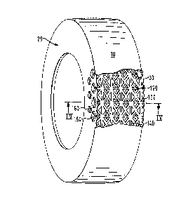
Figure 1 is a partial perspective view of a tire
tread embodying the principles of the invention;
Figure 2 is an enlarged plan view of a portion of
the tire tread;
Figure 3 is an enlarged plan view of a section of
the tire tread surface;
Figure 4 is a cross section view of the tire taken

214
along plane 4-4 in figure 1.
A tire 10 is divided into a sidewall section 20 and
a road engaging surface 30. The road engaging surface 30
is the portion of the tire body 10 which under normal
conditionsis in contact with the road surface. The side-
wall section 20 of the tire body 10 is the portion which
connects the road engaging surface 30 to the beads on a~
tire that is mounted on the rim of a wheel.
Figure 2 is a plan view of a rectangular tread
block unit 40. The rectangular tread block unit 40 has
major sides 60 and minor sides 70. Rectangular tread block
40 is divided into triangular lands 80 by diagonal
grooves 140 which extend between opposing corners of
rectangular tread block unit 40. In one preferred embo-
diment, the triangular lands 30 at minor sides 70 areconstructed as equilateral triangular lands 90 and the
triangular lands 80 with major sides 60 are constructed
with isosceles triangular lands 100.
A sipe 110 is grooved into the triangular lands
90 from the midpoint of the minor sides 70. The groove
; of sipe 110 extends approximately one fourth the distance
from minor side 70 to the opposing corner of triangular
land 90.
As shown in figure 3, rectangular tread block units
25 40 are spaced such that transverse grooves 120 and cir-
cumferential grooves 130 are formed, and so that the dia-
gonal grooves 140 of the rectangular tread block units
40 are in axial alignment. Each side of road engaging
surface 30 is comprised of a plurality of similarly
spaced apar-t rectangular block units 50 which are appro-
ximately one-half of the width of rectangular block units
40. The widths of circumferential grooves 130 and dia-
' gonal grooves 140 are substantially equal. The width of
the groove in the sipe 110 and the transverse groove
are also substantially equal and approximately one-half

621~
the width of circumferential groove 130 and diagonal
groove 140.
As shown in figure 1, a first plurality of spaced
apart diamond shaped lands 150 are located on the tire
sidewall 20 adjacent the road engaging surface 30. Each
of the first diamond shaped lands 150 are centered on
each -transverse groove 120. A second plurality of spaced
apart diamond shaped lands, 160, are disposed on tire
sidewall 20 adjacent to the lands 150. Diamond shaped
lands 160 are of approximately one-half the size of
diamond shaped lands 150. Diamond shaped lands 160 are
positioned further up the tire sidewall 20 and between
adjacent diamond shaped treads of diamond shaped lands.
Representative Drawing
A single figure which represents the drawing illustrating the invention.
Administrative Status

2024-08-01:As part of the Next Generation Patents (NGP) transition, the Canadian Patents Database (CPD) now contains a more detailed Event History, which replicates the Event Log of our new back-office solution.

Please note that "Inactive:" events refers to events no longer in use in our new back-office solution.

For a clearer understanding of the status of the application/patent presented on this page, the site Disclaimer , as well as the definitions for Patent , Event History , Maintenance Fee  and Payment History  should be consulted.

Event History

Description Date
Inactive: IPC from MCD 2006-03-11
Inactive: Adhoc Request Documented 1994-07-16
Time Limit for Reversal Expired 1994-01-18
Letter Sent 1993-07-16
Grant by Issuance 1991-07-16

Abandonment History

There is no abandonment history.

Owners on Record

Note: Records showing the ownership history in alphabetical order.

Current Owners on Record
JANUARIUS L. MECHTEL
Past Owners on Record
None
Past Owners that do not appear in the "Owners on Record" listing will appear in other documentation within the application.
Documents

To view selected files, please enter reCAPTCHA code :


To view images, click a link in the Document Description column (Temporarily unavailable). To download the documents, select one or more checkboxes in the first column and then click the "Download Selected in PDF format (Zip Archive)" or the "Download Selected as Single PDF" button.

List of published and non-published patent-specific documents on the CPD .

If you have any difficulty accessing content, you can call the Client Service Centre at 1-866-997-1936 or send them an e-mail at CIPO Client Service Centre.

({010=All Documents, 020=As Filed, 030=As Open to Public Inspection, 040=At Issuance, 050=Examination, 060=Incoming Correspondence, 070=Miscellaneous, 080=Outgoing Correspondence, 090=Payment})


Document
Description 
Date
(yyyy-mm-dd) 
Number of pages   Size of Image (KB) 
Claims 1993-10-20 2 60
Abstract 1993-10-20 1 17
Drawings 1993-10-20 2 55
Descriptions 1993-10-20 4 132
Representative drawing 2001-11-14 1 9