Language selection

Search

Patent 1286250 Summary

Third-party information liability

Some of the information on this Web page has been provided by external sources. The Government of Canada is not responsible for the accuracy, reliability or currency of the information supplied by external sources. Users wishing to rely upon this information should consult directly with the source of the information. Content provided by external sources is not subject to official languages, privacy and accessibility requirements.

Claims and Abstract availability

Any discrepancies in the text and image of the Claims and Abstract are due to differing posting times. Text of the Claims and Abstract are posted:

  • At the time the application is open to public inspection;
  • At the time of issue of the patent (grant).
(12) Patent: (11) CA 1286250
(21) Application Number: 1286250
(54) English Title: SILICONE MILKING UNIT
(54) French Title: ELEMENT EN SILICONE POUR LA TRAITE
Status: Expired and beyond the Period of Reversal
Bibliographic Data
(51) International Patent Classification (IPC):
  • A01J 05/08 (2006.01)
(72) Inventors :
  • KUPRES, STEVEN J. (United States of America)
(73) Owners :
  • AVON HI-LIFE, INC.
(71) Applicants :
  • AVON HI-LIFE, INC. (United States of America)
(74) Agent: SMART & BIGGAR LP
(74) Associate agent:
(45) Issued: 1991-07-16
(22) Filed Date: 1987-03-13
Availability of licence: N/A
Dedicated to the Public: N/A
(25) Language of filing: English

Patent Cooperation Treaty (PCT): No

(30) Application Priority Data: None

Abstracts

English Abstract


ABSTRACT OF THE DISCLOSURE
Disclosed herein is a teat cup assembly for
use with a silicone liner. The one piece shell for the
teat cup assembly has an integral peripheral protecting
wall which projects beyond the end of the cylindrical
shell wall and forms a recess for receiving the cuff of
the liner. The flange protects the end of the
inflation from damage caused by impact with the floor
or other articles in the milking parlor. No mechanical
parts are required to maintain the liner and assembly
in the shell.


Claims

Note: Claims are shown in the official language in which they were submitted.

- 6 - 64181-24
THE EMBODIMENTS OF THE INVENTION IN WHICH AN EXCLUSIVE
PROPERTY OR PRIVILEGE IS CLAIMED ARE DEFINED AS FOLLOWS:
1. A teat cup for use in an automatic milking system which
includes a source of constant vacuum and a source of pulsating
vacuum, said teat cup assembly including a teat cup inflation with
a proximal and distal end and a teat cup shell with connections on
the shell to the said sources of the vacuum and the inflation
including the longitudinal teat receiving chamber and a cuff with
an inturned flange located above and spaced from said distal end,
the improvement wherein said shell has a cylindrical wall portion
with a distal end and proximal end, a peripheral protective wall
portion integrally joined with said shell on the outside thereof
adjacent to the distal end and flaring outwardly and projecting
axially beyond said distal end to form an annular frusto-conical,
ring-shaped tapered recess receiving the inflation cuff in a seal-
ing press fit and providing a fluid seal between said cylindrical
wall portion of said shell and said cuff on said inflation and
said protective wall portion preventing direct impact on said
cuff.
2. A teat cup for use in an automatic milking system which
includes a source of constant vacuum and a source of pulsating
vacuum, said teat cup assembly including a teat cup inflation
having a distal and proximal end and an inturned flange spaced
from the distal end and formed of silicone rubber and a teat cup
shell with connections on the shell to the said sources of the

- 7 - 64181-24
vacuum and the inflation including the longitudinal teat receiving
chamber and a cuff with a flange and a spaced wall portion, the
improvement wherein said shell has a cylindrical wall portion with
a distal end and proximal end, a peripheral protective wall por-
tion joined with said shell on the outside thereof adjacent the
distal end and wall portions spaced from said wall portion and
projecting axially beyond said distal end of said inflation to
form an annular recess for receiving the flange of the cuff and
protecting said cuff from damage.

Description

Note: Descriptions are shown in the official language in which they were submitted.


- 1 - 64181-24
SILICONE MILKING UNIT
-
Background of the Invention
The invention relates to teat cup assemblies employing a
silicone inflation or liner with an outer shell. Use of silicone
inflations or liners rather than natural or synthetic rubber is
known to be desirable. An article in New Zealand Journal of Dairy
Science and Technology, 12.238-241, 1977, discusses the advan-tages
of use of silicone as compared to teat cup liners made from syn-
thetic or natural rubber. Basically the silicone inflations or
liners do not absorb butter fat and oils or moisture as do the
rubber liners. Additionally, silicone has resistance to extremes
of temperature, ability to retain its flexibility even at low
temperatures and good resistance to sunlight, oils, solvents and
other chemicals. However, the silicone does have certain disad-
vantages and the commercial silicone teat cup liners suffer from
these disadvantages. Silicone has a low tear resistance and is
easily punctured. This problem is noted as the primary disadvan-
tage of silicone liners in the above-cited New Zealand article.
In the art silicone inflations have been developed to fit existing
shells designed for rubber inflations and very little attention
has been devoted to developing a shell adapted to protect the
silicone inflation. In one prior ar-t device made by BouMatic the
distal end of the liner is exposed to impact and can be damaged Dy
a variety of impacts for example, hitting the concrete floor, or
the grates in the milking parlor, hitting other cups or equipment
and even being stepped on by the cow. An impact on the distal end

~2~36Z~f~
- 2 - 64181-24
can cause a shearing action of the cap and shell to cause damage.
Accordingly, the useful life afforded by the use of silicone which
is normally significantly higher than that for a rubber inflation
can be shortened considerably by an impact of this character which
can split, tear or cause puncturing of the silicone inflation.
U.S. Patent 4,459,938 discloses a teat cup assembly
employing a two-piece silicone rubber inflation with an entrance
member 20 and inflation 16. A mu:Ltiple piece shell with a pro-
tective cap covers the distal end of the inflation. This patent
shows a structure which is difficult to assemble and disassemble
and result~ in hard to clean pockets which can collect dirt.
` Other types of shell constructions such as those illu-
strated in U.S. patent 4,332,215; 4,116,165 and 3,659,557 show
shells which afford some protection for the distal end of the
liner but require a ring to expand the liner to secure the liner
in place in the shell and to provide a seal. The machine install-
ation process to install the ring can tear the liner if a silicone
liner is employed.
Summary of the Invention
The invention provides a teat cup assembly with a rigid
one piece outer shell which has an annular projecting protective
flange which is integral with the main body of the shell and which
protects the distal end or cuff of the silicone liner from impact
damage which can occur with the prior art devices. The disadvan-
tages of the cup type two-piece shells and the ring type shells

36250
- 3 - 64181-24
are eliminated. The invention provides an easy-to-clean, inexpen-
sive one-piece teat cup assembly with integral liner and shell.
The protective flange on the shell extends and diverges
or tapers outwardly from the cylindrical body to afford a wedging
fit of the liner to provide effective sealing of the liner cuff to
the shell at the inlet end. The protective flange will also pre-
vent water from collecting between the shell and inflation in the
vacuum chamber. This engagement ;also prevents the inflations from
twisting, or liner becoming out of alignment, during normal
machine use.
Further objects, advantages and features of the inven-
tion will become apparent from the Disclosure.
Description of the Drawing
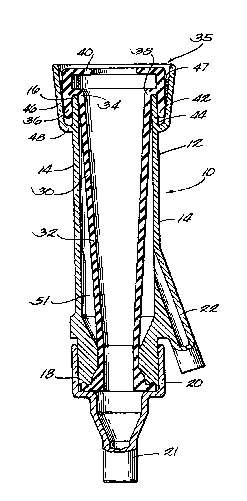
The figure is a sectional view of the teat cup assembly
of the invention.
Description of the Preferred Embodiment
Although the disclosure hereof is detailed and exact to
enable those skilled in the art to practice the invention, the
physical embodiments herein disclosed merely exemplify the inven-
tion which may be embodied in other specific structure. The scopeof the invention is defined in the claims appended hereto.
A teat cup assembly 10 includes a teat cup shell 12
which has a cylindrical wall portion 1~ having a distal end 16 and
a proximal end 18 which is adapted to be connected to a connector
20 with a nipple 21 which is connectable to a source of constant

~L2~36250
- 4 - 64181-24
vacuum. The shell 12 also includes an integrally formed small
diameter pipe 22 which is connectable to a source of pulsating
vacuum as is conventional in teat cup assemblies.
The flexible inflation 30 is desirably formed of sili-
cone rubber and includes a genera:Lly cylindrical wall portion 32
which forms a longitudinal teat receiving chamber with a distal
end 34 and cuff 35 including a spaced annular peripheral wall 36
joined to the cylindrical wall 32 by a connecting web portion 38.
The annular wall 36 has an inwardly extending or inturned flange
or lip 40. The cuff 35 includes an extension 42 on wall 36 which
is a continuation of wall 36 and extends downwardly from the web
portion 38 as viewed in the Figure. The overall outline of the
cuff is similar to that shown in U.~. patent 4,372,250 for a
rubber inflation except the cuff 35 can be wedge shaped. The end
extension 42 wedges within the recess 44 formed by the shell pro-
tecting wall portion or flange 46 which is connected to the shell
by a juncture portion 48. Flange 46 is flared outwardly and pro-
jects beyond the distal portion 16 of the shell in an axial
direction. The cylindrical wall portion 14 and wall portion 46
define the recess 44 which is ring-shaped and frusto-conical in
section. The wedging fit of the cuff 35 in the recess 44 prevents
twisting of the liner distal end in the shell. Adhesive can be
applied at 47 to secure the inflation in the shell. Use of the
integral flange 46 prevents entry of water into the shell during
washing which can occur with cap type assemblies.
The protective wall portion 46 provides lateral

~2&36~5~)
- 5 - 64181-24
protection to the cuff 35 of the silicone liner to prevent direct
mechanical contact and impact on the silicone liner. This greatly
enhances the life of the silicone liner.

Representative Drawing
A single figure which represents the drawing illustrating the invention.
Administrative Status

2024-08-01:As part of the Next Generation Patents (NGP) transition, the Canadian Patents Database (CPD) now contains a more detailed Event History, which replicates the Event Log of our new back-office solution.

Please note that "Inactive:" events refers to events no longer in use in our new back-office solution.

For a clearer understanding of the status of the application/patent presented on this page, the site Disclaimer , as well as the definitions for Patent , Event History , Maintenance Fee  and Payment History  should be consulted.

Event History

Description Date
Inactive: Reversal of expired status 2012-12-05
Time Limit for Reversal Expired 2008-07-16
Letter Sent 2007-07-16
Letter Sent 2002-01-23
Grant by Issuance 1991-07-16

Abandonment History

There is no abandonment history.

Owners on Record

Note: Records showing the ownership history in alphabetical order.

Current Owners on Record
AVON HI-LIFE, INC.
Past Owners on Record
STEVEN J. KUPRES
Past Owners that do not appear in the "Owners on Record" listing will appear in other documentation within the application.
Documents

To view selected files, please enter reCAPTCHA code :


To view images, click a link in the Document Description column. To download the documents, select one or more checkboxes in the first column and then click the "Download Selected in PDF format (Zip Archive)" or the "Download Selected as Single PDF" button.

List of published and non-published patent-specific documents on the CPD .

If you have any difficulty accessing content, you can call the Client Service Centre at 1-866-997-1936 or send them an e-mail at CIPO Client Service Centre.


Document
Description 
Date
(yyyy-mm-dd) 
Number of pages   Size of Image (KB) 
Abstract 1993-10-20 1 13
Claims 1993-10-20 2 47
Drawings 1993-10-20 1 20
Descriptions 1993-10-20 5 136
Representative drawing 2000-07-25 1 18
Courtesy - Certificate of registration (related document(s)) 2002-01-22 1 113
Maintenance Fee Notice 2007-08-26 1 172
Fees 2001-07-11 1 36
Fees 1997-05-20 1 57
Fees 1996-04-28 1 41
Fees 1995-04-30 1 41
Fees 1993-05-30 1 25
Fees 1994-05-23 1 47