Language selection

Search

Patent 1286512 Summary

Third-party information liability

Some of the information on this Web page has been provided by external sources. The Government of Canada is not responsible for the accuracy, reliability or currency of the information supplied by external sources. Users wishing to rely upon this information should consult directly with the source of the information. Content provided by external sources is not subject to official languages, privacy and accessibility requirements.

Claims and Abstract availability

Any discrepancies in the text and image of the Claims and Abstract are due to differing posting times. Text of the Claims and Abstract are posted:

  • At the time the application is open to public inspection;
  • At the time of issue of the patent (grant).
(12) Patent: (11) CA 1286512
(21) Application Number: 1286512
(54) English Title: ICE-CREAM MACHINE, PARTICULARLY FOR DOMESTIC USE
(54) French Title: MACHINE A FAIRE LA CREME GLACEE, PARTICULIEREMENT POUR USAGE MENAGER
Status: Expired and beyond the Period of Reversal
Bibliographic Data
(51) International Patent Classification (IPC):
  • A23G 9/12 (2006.01)
  • F25B 39/02 (2006.01)
  • F25D 11/00 (2006.01)
  • F25D 31/00 (2006.01)
(72) Inventors :
  • PANDOLFI, ALBERTO (Italy)
(73) Owners :
  • BREVETTI GAGGIA S.P.A.
(71) Applicants :
  • BREVETTI GAGGIA S.P.A. (Italy)
(74) Agent: MACRAE & CO.
(74) Associate agent:
(45) Issued: 1991-07-23
(22) Filed Date: 1986-05-22
Availability of licence: N/A
Dedicated to the Public: N/A
(25) Language of filing: English

Patent Cooperation Treaty (PCT): No

(30) Application Priority Data:
Application No. Country/Territory Date
53434-B/85 (Italy) 1985-05-28

Abstracts

English Abstract


ABSTRACT
In an ice-cream machine for domestic use, comprising a
fixed vessel (2), a container (3) for the product,
located within the vessel (2) and removable therefrom,
means (7) for mixing the product within the container
(3), and a cooling circuit including an evaporator coil
(10) associated with the fixed vessel (2), the passage
of the coil is defined between a pair of plates which
are connected together by the technique known as "roll
bonding" and which constitute the walls and bottom of the vessel
(2).
(Figure 1).


Claims

Note: Claims are shown in the official language in which they were submitted.

THE EMBODIMENTS OF THE INVENTION IN WHICH AN EXCLUSIVE PROPERTY
OR PRIVILEGE IS CLAIMED ARE DEFINED AS FOLLOWS:
1. An apparatus for producing ice cream comprising
a fixed vessel, a container housed within the vessel and
removable therefrom, means for mixing substances within the
container and a cooling circuit, said cooling circuit comprising
an evaporator coil housed in the walls of the fixed vessel, a
compressor having its inlet connected to the outlet end of said
evaporator coil, a capillary tube at the inlet end of the
evaporator coil, and a condenser having an inlet in
communication with the outlet of said compressor and an outlet
in communication with said capillary tube at the inlet of said
evaporator coil, said evaporator coil being defined between a
pair of plates connected together by roll-bonding in an integral
T-shape which forms and cools both sidewalls and bottom of said
vessel by forming the horizontal part of said T-shaped
evaporator coil into a cylindrical shape and by bending the
remaining part of the evaporator coil at right angles to said
horizontal part to define a bottom and by welding said sidewalls
and bottom together to define said fixed vessel.
-5-

Description

Note: Descriptions are shown in the official language in which they were submitted.


The present invention relates to ice-cream machines,
particularly ~or domestic use, of the known type comprising:
an apparatus for producing ice cream comprising a fixed vessel,
a container housed within the vessel and removable therefrom,
means for mixing substances within the container and a cooling
circuit, the cooling circuit comprising an evaporator coil
housed in the walls of the fixed vessel, a compressor having its
inlet connected to the outlet end of the evaporator coil, a
capillary tube at the inlet end of the evaporator coil, and a
condenser having an inlet in communication with the outlet of
the compressor and an outlet in communication with the capillary
tube at the inlet of the evaporator coil, the evaporator coil
being defined between a pair of plates connected together by
roll-bonding in an integral T-shape which forms and cools both
sidewalls and bottom of the vessel by forming the horizontal
part of the T-shaped evaporator coil into a cylindrical shape
and by bending the remaining part of the evaporator coil at
right angles to the horizontal part to define a bottom and by
welding the sidewalls and bottom together to define the fixed
vessel.
The object of the present invention is to provide an ice-cream
machine of the type specified above, which has a simple and
cheap construction and is guick and easy to assemble.
The main characteristic of the invention lies in the fact that
the passage of the evaporator coil is defined between a pair of
plates connected together by the technique known as "roll
bonding" and constituting the wall of the fixed vessel.
The invention will now be described with reference to the
appended drawings, provided purely by way of non-limiting
example, in which:
JJ:
B
.. .. . . . .. . .
- . . . . .. ~ . .
.. . . ~... . .

.Z~65~12
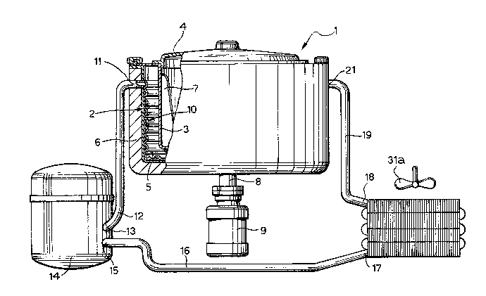
Figure 1 is a partially sectioned schematic view of an
ice-cream machine according to the invention,
Figure 2 is a view of a detail of Figure 1 on an
enlarged scale, and
Figure 3 is a plan view of the development of the wall
of the fixed vessel of the ice-cream machine
according to the invention.
Figure 1 illustrates an ice-cream machine 1 for
domestic use, including a fixed vessel 2 and a
container 3 for the product to be chilled, disposed
within the vessel 2 and removable therefrom. The
container 3 has an associated lid 4. In accordance
with the prior art, the container 3 is smaller than the
vessel 2 whereby an interspace 5 containing a liquid
with a low freezing point, for example a saline
solution, is defined between their side walls and
bottoms.
~ .
The fixed vessel 2 is surrounded by a casing 6 of
~ thermally-insulating material. Within the removable
.!'~ 20 container 3, which is intended to receive the product,
there is also provided, in known manner, a rotary tool
7 for mixing the product, mounted on a shaft 8 driven
by an electric motor 9.
:~
The ice-cream machine i has an associated cooling
~ 25 circuit whose components are housed within the housin~
; (not il~ustrated) of the ice-cream machine. The real
position of the various components within the body of
the ice-cream machine has not been illustrated in order
; to allow the components themselves and the connections
.~ ~
.,`' ~
.~ .
:' . ~, ' : . : : .. . .

lZ~3651~:
between them to be shown more clearly.
The cooling circuit of the ice-cream machine includes
an evaporator coil 10 associated with the fixed vessel
2 and having an outlet end 11 connected through a duct
12 to the inlet 13 of a hermetic compressor 14. The
outlet 15 of the hermetic compressor 14 is connected
through a duct 16 to the inlet 17 of a condensor 31
whose outlet 18 is connected through a duct 19 to a
capillary tube (which will be described with reference
to Figure 3) located in correspondence with the inlet
21 oE the evaporator coil 10. The condenser 31 is
constituted by a radiator having a fan 3la driven by an
electric motor (not illustrated).
:
In the prior art, the evaporator coil 10 is constituted
by a tube wound into a helix and housed in the
interspace 5.
According to the present invention, however, the
evaporator coil is formed in the wall of the fixed
vessel 2, which is constituted by a pair of plates 2a,
2b (see Figure 2) connected together by the technique
known as "roll bonding".
Figure 3 illustrates the development of the side wall
and the bottom of the fixed vessel 2 as they are made
by the aforesaid technique. After they have been made
in the developed form, the part théreof corresponding
to the side wall of the vessel, indicated 22 in Figure
3, is bent at a right angle to the part corresponding
to the bottom of the vessel, indicated 23. The part 22
is then formed into a cylinder and its two opposite
ends are joined together by welding or seaming to
. : : ~ , , ', -: . -
,,
: ' ' ' ' .
:
.
.

-
~LZ~65~X
define the fixed vessel.
As illustrated schematically in Figure 3, the
serpentine path has a constricted portion 24 in which
the capillary tube 25 of the cooling circuit is
intended to be housed. In Figure 3 the direction of
flow of the fluid through the evaporator is indicated
by the arrows.
Naturally, the principle of the invention remaining the
same, the constructional details may be varied widely
with respect to those described and illustrated purely
by way of example.
'~ .
.
.
~ .
.:
.~ .
, ..
, .
- - . . . : . :
: '. '~: .'' ' ' ' . . . : .
.'. , , . . ' : ' , ;, ' .. . . .

Representative Drawing
A single figure which represents the drawing illustrating the invention.
Administrative Status

2024-08-01:As part of the Next Generation Patents (NGP) transition, the Canadian Patents Database (CPD) now contains a more detailed Event History, which replicates the Event Log of our new back-office solution.

Please note that "Inactive:" events refers to events no longer in use in our new back-office solution.

For a clearer understanding of the status of the application/patent presented on this page, the site Disclaimer , as well as the definitions for Patent , Event History , Maintenance Fee  and Payment History  should be consulted.

Event History

Description Date
Inactive: IPC from MCD 2006-03-11
Inactive: Adhoc Request Documented 1994-07-23
Time Limit for Reversal Expired 1994-01-25
Letter Sent 1993-07-23
Grant by Issuance 1991-07-23

Abandonment History

There is no abandonment history.

Owners on Record

Note: Records showing the ownership history in alphabetical order.

Current Owners on Record
BREVETTI GAGGIA S.P.A.
Past Owners on Record
ALBERTO PANDOLFI
Past Owners that do not appear in the "Owners on Record" listing will appear in other documentation within the application.
Documents

To view selected files, please enter reCAPTCHA code :


To view images, click a link in the Document Description column. To download the documents, select one or more checkboxes in the first column and then click the "Download Selected in PDF format (Zip Archive)" or the "Download Selected as Single PDF" button.

List of published and non-published patent-specific documents on the CPD .

If you have any difficulty accessing content, you can call the Client Service Centre at 1-866-997-1936 or send them an e-mail at CIPO Client Service Centre.


Document
Description 
Date
(yyyy-mm-dd) 
Number of pages   Size of Image (KB) 
Cover Page 1993-10-21 1 19
Drawings 1993-10-21 2 81
Abstract 1993-10-21 1 15
Claims 1993-10-21 1 35
Descriptions 1993-10-21 4 148
Representative drawing 2000-07-26 1 39