Note: Descriptions are shown in the official language in which they were submitted.
TITLE OF INVENTION
impeller apparatus
TECHNICAL_FIELD
An impeller apparatus for agitating a liquid and pO8-
sibly a gas in a vessel, includ:ing an impeller and a rotatab-
le shaft carrying the propeller for rotation about the axi6
of the shaft in the liquid, the impeller including at least
two blades which have their leacling surfaces in the direction
of rotation formed for generating an outwardly directed, ra-
dial liquid flow. The apparatus may be used for mixing li-
quids, and particularly but not exclu6ively, for dispersing
gases into the liquid contained in the vessel.
BACKGROUND ART
The conventional method of dispersing gases into a
liquid is to use a mixing apparatus including a vessel for
the liquid, a rotating radial flow impeller immersed in the
liquid with its axis vertically oriented, and a gas distri-
bution jet or header in the vessel under the impeller. The
impeller or radial flow turbine thu~ disperses the gas intro-
duced into the liquid via tho gas jet means. When the blades
of the turbine are rotated in the liquid, the hydrostatic
pressure in front of the blades increases and decreases be-
hind the blades. This is a natural consequence of the hydro-
dynamic resistance which, together with the centrifugal and
Coriolis forces urge the fluid in a radial direction. How-
ever, the pressure difference results in that the gas bubbles
move to the low pressure area6 behind the blades, where they
collect and combine into larger gas cavities. In practice,
these cavities result in a streamline forming of the blades,
which signifies a drastic reduction of the hydrodynamic re-
sistance, and thu6 also a drastic reduction of the power re-
quired to rotate the turbine. In order to retain a desired
degree of agitation, it is therefore necessary to instal a
very much greater and thus more costly agitatior than would
otherwise be required. In addition, disper6ion of the gas in
l'~`f~6'~6~3
~.,
the ]iqu:ld :is nl~ldf- rnore d:i~ ell:Lt h~,~ the rnentioned coalescing of
the gcls hubhlec: arld ti-le formatiorl of lartJer ga.s volumes orl the
trai:l.iny sides of -the b:Lades.
The caC;e may also hF:' concel.ved where a :Li-.luid that ic to
be rn:i.xed contcl ins clissolve(l yclses which i t iS desired to retain
dissolved ln the l.:Lqll:id. I-t m-,y thcen ~lappen that these gases
depart from the liclulcl c-lue to the l.0~7 press~lre regions behind the
blades, forming gc~s cavl.tie.-. behincl the blades, and qradually
departing from the l.icluid in the form of :Large gas bubbles. The
pressure on the trai:l:Lny surfaces of the blades may also be so 10~;7
that -the li.cJuid is vapouri~ed and -the generated vapour forms the
ment.ioned CJaS cavities so that in practice -these caviti.es
drasticalli~ :reduce the driving power of the turhine.
A first object of the invention is therefore -to provide
a blade configura-tion for a turbine or impeller of the indicated
kind, such that the driving power of the impeller does not fall
due to the occ~urrence of such gas cavities on the trailing sides
of the blades during operation of the apparatus, particularly in
connection with the dispersion of gas into the liquid.
SUMMARY OF THE INVENTION
The invention provides an impe:ller apparatus for
agi-tating a liquid and dispersing a gas introduced therein in a
vessel, the apparatus comprising: an impeller; a rotatable
vertical shaft carrying -the impeller for rotation about an axis of
the shaft in said liquid; and means for introducing the gas in-to
the liquid below the impeller; said impeller comprising a disc
perpendicularly mountecl on the shaft to be rotated -therewith, and
at least two turbine blades separately mounted to the disc at the
12~6~
2a
outer periphrry of thP dLse and projeetlrlc~ outf/ar~ tllerefrom,
eae}l b.l.ade hclvi.ncl a :leacl.i.ng surtaee arld a tra~.lincl surfaee ~ th
regarcl to a d:ireei;lorl o:c rotatlorl of the impel.ler, eclch leading
surfaee beinci forlrled allf,l or:i.erltf d for- produe:ing a substantially
raclia:lly outwarclLy d:ire~ted Liqllid fLou, and eaeh trailing surfaee
havincJ a s.ubstantlal:Ly streamlined eross seetlon whi.eh is
subst,,n-tially syn!metr-Loally re.Lative to a plane of movement of an
axis of t;he l:~:Lade arlcl wll:i.(-h llcl5 a shdrp spine in said plane.
As mentloned ahove, the l:Lclllid :is agitated by a
eombina-tlon o:t hiclh arld :Low hyclrostati- pressures inside the
licluid. This is analocJous w:ith the situatiorl rouncl the wincJS of
all aircraftr as we:Ll as other aero- and hydrofoils. P,y filLincJ,
:in aeeorclanee with the :Lnven-tion, -the low pressure region hehind
-the blades wi-th struetural material, where -this region eould
otherwlse be filled with gas when the blacles eonventionally have a
flat trailing surfaee, these reg:ions are no loncler available for
the forma-tion of large gas eavi.ties. Aeeo.rd:inqly, :in -the
invention tlle trailing slde of each b:Lade is physically
streamlined, and in the case of dispersion of gas in the liquid,
this signifies that the quotient
6~3
between the turbine starting power and operational powsr is
substantially constant in relation to the quotient Q/ND3,
where 4 denotes the gas flow, ~I the rotational speed of the
turbine and D the turbine diameter, in the normally utilized
quotient interval.
Preferred embodiments of the invention are disclosed in
the appended subclaims.
In mixing apparatus of the type in question, the blades
may be for~ed by straight elements, the efEective, straight,
leading surface of which is adapted such that the blades are
oriented in an 1nterval defined by the effective leading sur-
face of the blade being swept backwards in the direction of
rotation by 45 from the radial direction, and by the effect-
ive leading surface of the blade extends radially. Since the
impeller or turbine blades are adapted to produce a substan-
tially pure radial flow, they may have a leading surface
which iB 6ymmetrical in relation to the plane of rotation of
the blades. Accordingly, the blades may have a flat leading
surface, or it may be of a concave configuration. In order
that the trailing surface of the blades may be regarded as
streamlined, the trailing side of the blade should have a
sharp edge defining the portion of the trailing side of the
blade situated furthest from its leading side. The trailing
side of the blade can be generally regarded as having a cross
section in the form of an equilateral triangle, the base si-
des of which define the edge lines of the leading surface of
the blade. The "triangle legs" merging together into said
edge may optionally be straight, but are preferably ymmetri-
cally curved, their concave sides facing towards each other.
The blades may be formed from sectors of straight, circular
or tapering tubes, these sectors being folded along a central
line to be given the mentioned sharp edge. In accordance with
the invention, it is thus not sufficlent to form the trailing
side of the blade from a sector of a circular-cylindrical
tube without symmetrically folding this sector.
The blades in accordance with the invention may have
i6(~
the form of a generally V-shaped plate, the concave side of
which may be filled or closed off by structural material.
Preferably, the blades are formed with a leading surface, the
longest dimension of which, i.e. length dimension, extends
radially, and of which the width dimension is constant or
tapering radially outwards.
The invention will now be described in detail with the
aid of an unrestricting example and with reference to the
accompanying drawing.
DRAWINC
Figure 1 schematically illustrates an agitating appara-
tus for dispersing ga~ into a liquid.
Figure 2 is a section taken along the line II-II in
Figure 1.
Figure 3 is a aection through a first embodiment of an
impeller blade in the apparatus, taken along the line A-A in
Figure 2.
Figure 4 iB a section corresponding to the one on
Figure 3 of another inventive blade.
Figure 5 is a section along the line C-C in Figure 2 of
a blade according to Figures 3 or 4.
Figure 6 is a view of an alternative inventive blade
configuration.
Figure 7 is a view taken along the line B-B in Figure
6, to illustrate a first cross-sectional configuration of
such a blade.
Figure 8 is a second cross-sectional configuration,
along the line B-B in Figure 6.
Figure 9 is a cross-section along the line B-B in
Figure 6 of a third variation of blade cross-sectional
configuration.
Figure 10 illustrates the flow conditions round a
conventional impeller blade.
Figure 11 illustrates the flow conditions round an
impeller blade in accordance with the invention, correspond-
ing to the olade in Figure 3.
Figure 12 schematlcally lllustrates a blade in accord-
ance with the invention with a flat leading surface and a
homogeneous cross-section.
Figure 13 ie a ~raph illustrating the power variation
for impeller drive in response to supplied gas quantity, im-
peller revolutionary speed and diameter for dispersing gas
into a liquid with the aid of an apparatus in a~cordance with
the invention and an apparatus according to the state of the
art.
EMBODIMENT EXAMPLES
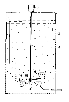
Figure 1 schematically illustrates a cylindrical, open
vessel 1, the wall of which is provided with vertical baffles
2 for preventing rotation of the liquid in the vessel. In the
bottom region of the vessel there is an annular jet means 3,
with the aid of which a cylindrical gas bubble curtain is
introduced into the liquid. A vertical shaft 4 is arranged
coaxial with the means 3 and is mounted for rotation with the
aid of a drive unit 5. The bottom end of the shaft 4 carries
a disc 61 coaxially mounted above the jet means 3. In accord-
ance with the invention, the disc 61 has blades 62 in its
edge region. Figures 2 and 5 illustrate a first type of in-
ventive blade, which has a substantially constant height
along its radial extension. Figure 3 illustrates a first
cross-sectional configuration of this blade, and it will be
seen that the blade 621 comprises a segment of a circular-
cylindrical tube with the radius R, this segment being taken
along tube generatrices and is folded along a central genera-
trix to form a spine 63. The blade is preferably slit at one
end along the spine 63 for conventionally enabling fitting
onto the disc 61. The blade 621 has a width B wich is greater
than half its height h. The convex surface of the blade 621
forms the trailing aurface of the blade and its concave sur-
face iB its leading surface. The blade 621 is mounted on the
disc 61 ao that the spine 63 extends radially or with a back-
ward sweep of at most 45. Since the blade 621 has a sharply
6~
defined spine 63, no notable gas cavities occur behind the
blade during operation. By the generally V-shaped blade being
formed on from a tubular blank, its trailing side has a par-
ticularly favourable streamline configuration. Pigure 4 illu-
strates an alternative blade cross-section for the blade con-
figuration apparent from Figure~ 2 and 5. The blade 622
according to Figure 4 is formed from a flat trapezoidal plate
blank, which is folded along a line of symmetry so that a
sharp, straight spine 63 is formed, and 80 that the height h
of the blade will be less than its width b. As with the embo-
diment according to Figure 3, the spine 63 and the relation-
ship b greater than h/2 ensure that the blade is given a
streamlined configuration suitable to the purpose, 80 that no
gas cavities can be formed behind the blade during operation.
The apex angle ~ in Figure 3 i8 thUB le8B than 180, and the
apex angle ~' in Figure 4 is less than 60.
In impeller apparatus of the radial flow type in quest-
ion here, it may be to the purpose to allow the height of the
blades to decrease radially outwards. Figure 6 schematically
illustrates such a blade type In this case the blade 623
according to Figure 8 may be formed from a sector of a circu-
lar-cylindrical tube blank, the sector being formed by the
tube being cut along a plane forming an angle to the axis of
the blank, the sector thus produced being folded along
central generatrix to form a sharp spine 63 so that the
cross-sectional configuration of the blade 623 corresponds to
the one for the blade 621 in Figure 3. Alternatively, the
blade may be formed by a tapering tubular blank with a circu-
lar cross section, a segment of the tapering tube being cut
out, e.g. along two generatrices, after which the generally
trapezoidal segment iB folded along a central generatrix
which is a line of symmetry of the segment, to form a sharp
spine 63 on the blade 624 according to Figure 7. The cross-
-sectional configuration of the blade according to Figure 7
corresponds to the one according to Figure 3. The blade embo-
diment according to Figures 6 and 9 is formed by a flat tra-
pezoidal plate blank being folded along a line of symmetry to
form a sharp spine 63, the crosasectional configuration of
the blade 625 according to Figu:re 9 then correspondlng to the
one according to Figure 4.
In the embodiments according to Flgures 7, 8 and 9, the
long edge of the blade is in one plane which is parallel to
the axial direction of the impe:Ller when the blade i8 fitted.
The blades according to Figures 4, 7, 8 and 9 are also prefe-
rably slit at one edge along the spine 63 for permitting easy
fitting to edge of the disc 61. The blades according to Figu-
res 3, 4, 7, 8 and 9 can be used in the illustrated form,
since they are symmetrical in relation to a plane through the
spine 63, 80 that when the blades are fitted to generate a
pure radial flow, both long edges of the blades are in a
plane parallel to the impeller shaft. In the blade embodi-
ments apparent from Figures 3, 4, 7, 8, 9, i.e. blades with a
concave leading side, a high pressure region is formed on
their leading sides, 80 that the flow picture in crosssection
through the longitudinal direction of the blades is substan-
tially the same as if the concave leading sides of the blades
were filled by structural material.
In the embodiments according to Figures 7, 8 and 9, the
direction of the spine 63 defines the effective direction of
the blade relative a radius in the fitted condition of the
blade. However, should the blades according to Figures 7, 8
and 9 be filled with structural material on their leading
sides, resulting in a flat leading surface in a plane through
the long edges of the blades, this surface would define the
effective direction of the blades relative the radius in a
fitted condition.
Figure 10 schematically illustrates a cross-section
through a conventional impeller blade for an apparatus of the
~cind illustrated in Figures l and 2 during operation for dis-
persing a gas into a liquid. It will be seen that a large gas
cavity is formed on the trailing side of the blade. The in-
ventive blades eliminate the occurence of such gas cavities
1~86~ 0
by their havlng been given a tralllng side which has substan-
tially the aame shape as the gas cavity behind a blade with a
flat trailing surface.
Figure 11 illustrates the flow pattern in a cross sect-
ion through a blade in accordance with the invention, e.g. a
blade according to the Figures 3, 7 and 8, and Figure 12 il-
lustrates the flow picture in a cross section through a cor-
responding blade having a leading concave side filled with
structural material.
Figure 13 illustrates the power requirement as a funct-
ion of the gas flow for a conventional centrifugal turbine
and for the inventive centrifugal turbine RGT, as driven for
dispersing gas into a liquid in an apparatus generally
according to Figures 1 and 2. In Figure 13, P/Po indicates
the driving power/starting power and Q/ND3 the quotient be-
tween the gas flow and the product of the turbine revolution-
ary speed and the cube of the turbine diameter. It will be
seen from Figure 13 that the driving power falls dra6tically
with increasing gas flow for a conventional centrifugal tur-
bine, the blades of which have a flat trailing side, and that
the driving power for a centrifugal turbine having inventive
blades is substantially constant for varying gas flow within
the interesting range for apparatus of the type in question.
The results according to Figure 13 are obtained with a cen-
trifugal turbine having a diameter of 150 mm, a revolutionary
speed of 400 rpm and flat blades, in comparison with an in-
ventive turbine with a diameter of 250 mm, a revolutionary
speed of 180 rpm and blades according to Figure 3 having the
angle ~ = 120, b ~ h~/2 and R = h.
In accordance with the invention, a centrifugal flow
impeller is achieved having blades which are symmetrical re-
lative to a central plane coinciding with the plane of rota-
tion of the blades. The trailing surface of the blades is
terminated by a sharply pronounced spine in the plane of sym-
metry. The spine has rectilinear extension. The blade may be
readily manufactured starting with a flat plate blan~, a cir-
~5~6~
cular-cylindrical tubular blank or a tapering tubular blank
wlth a circular cross-section. The blank has a substantially
rectangular or trapezoidal confi.guration and is folded about
a line of symmetry to form a sharp spine. In the case of
blanks in the form of sectors of tubular starting material,
the blank i8 folded 80 that the concave surfaces of the blank
halves face each other. In a cross-section through the longi-
tudinal direction of the blades the distance between both
free edges of the blade is greater than the extension of the
blade in its plane of symmetry Since the concave side of the
blade is the leading side thereof, the hydrostatic pressure
will be high, and thus no gas cavity will be generated in the
leading surface concavity of the blade. If 80 desired, this
concavity can be filled with structural material up to a sur-
face extending through the free edges of the blade.
In Figure 3 the angle ~ = 120, b = h~/2 and R = h. In
Figure 4 the angle ~' ~ 60.
The angle between a line passing through the upper and
lower edges of the blade and the trailing blade surface con-
tiguous thereto attains to at least 55 and at most about 90
in a cross-section through the blades, i.e. in the normal
plane to the longitudinal direction of the blade. This angle
iB preferably 90 in the embodiments according to Figures 3,
7 and 8. In Figures 4 and 9 this angle is about 60. It
should be clear, however, that the embodiments according to
Figures 4 and 9 may be modified with further folding lines 80
that the cross-sectional configuration of the trailing sur-
face of the blade approximates the one according to Figure 3,
for example, where the angle may attain to 75 while ~ re-
mains 60. Common to all embodiments is that b is preferably
equal to, or greater than 0.7 h. In all the blade configura-
tions the contours of the blade trailing edge are decisive
for the properties of the apparatus, and the leadlng side of
the blade may be a concave surface which is symmetrical in
relation to the plane of symmetry of the trailing blade sur-
face, or a flat surface where the latter may be formed by the
~ ~36~;(3
leading surface of a plate section defining the trailing sur-
face of the blade is completely or partially filled with a
structural material, or by a plain flat plate being connected
between the edges of the plate section, and optionally fill-
ing in the ends of the resulting hollow section.
Preferable, the longitudinal aXiB of the blade extends
generally radially to the impeller shaft.
Although the blades normally are oriented with their
longitudinal axis in a normal plane to the shaft axis, it iB
appreciated that deviations from such geometry are possible.
Thus, the longitudinal axis of the blade could be curved
(possibly in a shaft axial plane) and/or form an angle with
said normal plane. The surface defined by the blade axis as
the impeller rotates could then (adjacent the blade) be con-
sidered as the "plane of symmetry" for the blade.
The critical streamlined cross-section is defined by
the relative liquid flow direction around the blade.