Note: Descriptions are shown in the official language in which they were submitted.
6~g~
The present invention generally relates to
ver~ical, cross-wind axis wind turbines having plural
~ind driven blades with variab]y adjusted orientation to
incident wind.
~Yind axis and cross-wind axis turbines are the ~-
predominant wind turbines presently in use and under
study. ~ wind axis turbine includes a number of blades
mounted for rotation about a central horizontal column
having an axis of rotation that must be closely aligned
witll the wind to produce power efficiently. Since wind
direction tends to vary over time at most sites, high
efficierlcy can be achieved only if the horizontal axis
can be rotated to provide the close alignment. However,
structure for rotating the horizontal axis into the wind
tends to be expensive, resulting in poor power-cost
ratios for very high power wind turbines.
Wind driven vertical turbines typically include an
assembly of airfoils or blades mounted for wind-driven
structure. Vertical wind driven turbines respond to
wind from any direction without shift of the column or
base stLucture thereof. ~lowever, to improve blade
~5 efficiency, by obtaining a more favorable blade angle of
attclck to the wind, it is often necessary to rotate each
blade about an individual axis thereof as the assembly
rotates about the vertical column. Known structures
sucll as a type disclosed in ~. S. Patent No. 4,049,362
to R~n~er, a ring gear arrangement as disclosed in ~. S.
~.
.' ' ., . ,, ,- .
~2~36995
Pa~ent 3,9~3,072 to Quinn, or a circular track and
bearing arrangement as disclosed in German Patent
7~2,7~ to ~lartwagner. The blade angle oE attack
control structures disclosed in the aforesaid patents
also vary the blade in response to
changes in wind speed or velocity.
The foregoing blade control arrangements have a
number of disadvantages, one being that a hiyher than
a~erage on site wind velocity is often necessary to
overcome inertia of the ring gear, gear train or
circular track mechanisms to initiate turning of the
blades. Also, to maintain blade rotation, a certain
amount of wind power is necessary to overcome inertia of
the ring gear, gear train or circular track mechanisms
! 15 to initiate turning of the blades. Also, to maintain
blade rotation, a certain among of wind power is
necessary to overcome friction generated by these blade
control mechanisms, adversely affecting power/cost -
ratios. Further, since gears employed in these prior
art mecllanisms rotate constantly, in wearing contact
with each other, and operate under variable wind
velocity conditions, frequent maintenance and/or
replacement may be necessary, particularly after periods
of excessive wind velocities. To generate sufficient
wind uower to achieve economical operation, vertical
wind turbines generally include large airfoils. Devices
to control such airfoils can be very costly.
Another problem associated with certain known
relatively high efficiency cross-wind axis wind turbines
is that the blades have complex shapes, thus being
expensive to manufacture. Other turbines of this type
are inefficient because the blades are not designed so
they are always oriented to the wind for op,timal wind
'' ' '' '' .< I ~ , , :
.
' ,
~X~3699.~
-- 3
energy absorption.
In the fields of wind turbines and vertical-axis--types in
general, the airfoil or blades must perform under the condition
of wind pressure reversal for each revolution of the turbine and
therewithal in a given design shape the blade must therein per-
form well. However, this is not always the situation; often a
trade-off on performance has been required within the blade
design shape to give better performance on wind flows on one side
than on the other side.
An example of a vertical axis wind turbine with an airfoil
design that is far better suited for deriving energy from one
side of an airfoil blade than the other side, is U.S. Patent No.
4,130,380 by Kaiser. In addition, there are designs that use
large massive structures in an attempt to improve the channelling
and compressing of wind flows, namely in such patents as U.S.
Patent No. 4,490,623 by Goedecke or Canadian Patent No. 1,027,052
by ~aumgartner. Yet another type of design used for an improve-
ment of wlnd flows is the use of an end plate angled on the blade
ends, which would give some improvement on one side over the
other side thereof, the main function being to keep the air flows
from merging on the blade ends and a stated control means of
turbine speed, as provided by U.S. Patent No. 4,255,085 by Evans.
Another design which has been tried involves the use of flexible
rubber or plastic blades which bend into a contour shape, to
adjust the wind flows to provide circular rotation about the
axis, as provided in German Patent No. 28270044 by Lagarde. This
.
~ :.
: , , . :. . , . : ~
.
.
~ 2~3~99~
design would, however, have a stability problem, e.g., of the
blades may get out of synchronous balance with each other and
~ would be subject to fatigue of the blade materials. The use of
5 troughs has been attempted on ship screws and rudders, as indi-
cated by U.S. Patent No. 1,465,593 by Barrett et al, and French
Patent by Jacquemin 773,033 ~which provide a single-sided
trough), in British Patent No. 838,868 and U.S. Patent No.
2,962,101 (which provide ship screws), U.S. Patent No. 2,899,128
by Vaghi (which provide an air blower), and U.S. Patent No.
2,013,473 by Meyer (which provide a fluid propeller and fan
blade). U.S. Patent No. 1,861,065 by Poot described a propeller
screw having serrated blades.
Vertical, wind-driven turbines typically include an assembly
of airfoil blades mounted to a wind-driven shaft of a supporting
axis-type structure, with a capability to respond to wind flows
deriving from any direction without a shifting of the structural
¦ mass. One effect of wind flows on the airfoils causes circula-
tory vertical travel about its central path. In addition, a tur-
bulent air flow about the airfoil surface derived from a rever-
sing of pressure flows upon the airfoil blades occurs. Another
problem of airfoils in general requires the slowing of the air-
flows on the wind incident side of the blades, while substan-
tially simultaneously requiring an increase in the airflows on
the other side of the airfoil. A useful type of airfoil-blade
for vertical axis wind turbines that is well suited to the pro-
blem of wind pressure reversal, should be an airfoil design that
:,.
.
', ~ ' .
.
performs equally well to the high and low pressure changes on the
blades upon exposure of wind thereon. Another desired affect is
to cause circulatory travel about a vertical axis to provide an
5 improvement of energy transfer in lower wind velocities onto the
blades. Another aim would be to cause the wind flow to slide
``~ into the contouring troughs and in so doing to slow-down and
modify the wind flows to provide fGr optimizing the transfer of
wind energies to the turbine blades, thereby to provide a greater
output of total energy. A number of wind turbines are presently
in use which would need to be improved by the provision of aero-
dynamic airfoil blades that are better suited for the transferr-
ing of energy velocities of winds onto the blades for generating
;- sufficient power. This aim is to achieve economical operations,
so as to overcome the present cost-to-power ratios that adversely
affect a useful development of wind turbines.
The best mode for achieving these effects is provided by a
- uniquely-shaped blade having a series of contour troughs along
its length for channelizing of wind flows therein, to maximi7e
20 the transferring of energies to the blades. The troughs are
respectively staggered in relation to each other along the blade
length so that each trough defines an airfoil-shaped blade seg-
ments within a triangulation of intersecting troughs along the
blade length. In such manner, the wind currents striking the
blade surface will diverge and decelerate as they flow through
each trough towards the trailing edge. This effects a trans-
ferring of the wind energies by first slowing airflows on the
.~ .
:
.:: .
- . ~ . . . , :. :
~ .. - ~ . . ..
9~s
high pressure wind incident side, thereby to channel within the
troughs to effect a merging of the flows on the opposite side of
the blade (the low pressure side of the wind flows) to cause a
dropping of the wind flows. This causes a pressure drop, which
speeds up the airflows by the lowering of the incurring pressures
within the trough. The preferred range of the ratio of width
~W), to a depth of each trough is approximately ~:1 to 8:1, with
5:1 being best to minimize the total surface area of depths and
crests of the troughs and therein also to maintain the optimal
design to coact to modify of the wind-air flows on both sides of
the blade. This causes a blending and a merging of the wind-air
flows, thereby to equalize pressures and velocities, to cause a
minimizing of a trailing vortex of the blade wake. There are
several designs of the blade to accomplish these effects. In
such blade, the highest pressure of the high pressure side of ~-~
blade (wind incident side) is also the highest pressure of the
low pressure side. The other side of the blade having the lowèst
pressure on the trailing edge provides the lowest pressure on the
trailing edge of the wind incident side of the blade. This
brings about a merging of airflow within the merging wake of the
blade. This is a result of the design of the trough shape using
the "laws of Bernoullis flow dynamics" to improve the performànce
of the blades efficiency and drag coefficient.
It is accordingly an object of a broad aspect of this inven-
tion to provide a vertical wind turbine having a low inertia
blade control mechanism for controlling both the speed and -
~ ' ~
: ' . ....... . ' , , . . . '
:-
, . ~ - , . , . : . . . .
12~3699~;
orientation of plural vertical blades under variable wind con~
ditions to maximize conversion of wind power to usable power.
An object of another aspect of this invention is to provide
a wind turbine having a blade control mechanism that is econo-
mical in design and is capable of reliable operation in rugged
and hostile environments, as occurs in on-site wind locations.
An object of yet another aspect of this invention is to pro-
vide for controlled orientation of blades in the vertical wind
turbine to regulate angular velocity of the blades and hence
conversion efficiency of the turbine.
An object of still a further aspect of this invention is to
provide a wind turbine that is simple, reliable and inexpensive
to construct.
By one broad aspect of this invention, a wind-driven turbine
of the vertical axis type is provided comprising (a) a support
base, (b) a generally vertical column rotatably mounted to the .
support base; (c) upper and lower support means respectively
mounted on the column for rotation therewith; (d) a plurality of
wind driven blades connected between the upper and lower support
means for rotation about the column, each blade being indivi-
dually rotatable about a blade axis extending longitudinally
through the blade to vary a blade angle of attack thereof rela-
tive to wind velocity during rotation about the column; and (e)
control means for variably adjusting angles of attack of each
blade to incident wind, the control means including a connecting
rod means having a drive means for rotating each blade about the
~ ' ' ''
- , . - ' ' ' : ' ~
~LZ~ 39~
-- 8 --
associated blade axis in response to radial movement of the con-
necting rod means and control shaft pivotally mounted within the
column and having a first shaft portion connected to the connect-
ing rod means and a second shaft portion radially offset from thefirst shaft portion and pivotally connected radially to displace
the first portion and thereby the connecting rod means to vary
the blade angies of attack during rotation about the column,
wherein the upper support means includes four substantially-
identical spokes extending substantially-horizontally radially
; from the column, the connecting rod means including a connecting
rod extending through each upper spoke for connection of the :
drive means to a driven means mounted on a portion of a shaft
passing through each biade, wherein the control means urther
includes a plate to which three of the connecting rods are pivo-
tally affixed by spherical bearing means respectively spaced 90 ;
from each other, and a center spherical bearing mounted in the
plate to receive the first shaft portion therein, the fourth con-
necting rod being non-rotatably affixed to the plate periphery,
enabling radial displacement of the plate and connecting rods in
a generally-horizontal plane, wherein the control means further
includes a cylindrical bearing member rotatably mounted withln
- the column on races with the offset second shaft portion being . .
pivotally mounted within the cylindrical bearing by means of a
pivot pin affixed to an inner surface of the bearing mounted
cylinder.
.
- 8a -
Such turbine further preferably includes a compression
spring extending under the pivot pin on the second shaft portion
to contact the inner cylinder to bias the offset portion.
The linearity-dxiven blade means preferably includes a rack
affixed to the outer end of each connecting rod, the driven means
including a pinion meshing with teeth provided on each rack to
cause radial displacement of the connecting rods through the
alignment plate.
The turbine preferably also includes a wind vane structure
affixed to the first shaft portion above the upper spokes, the
vane causing rotational movement of the control shaft in response
to variations in wind direction, with wind velocity thereby caus-
ing pivotal arc movement of the second shaft portion and radial
displacement of each connecting rod through the control plate
radially to displace each rack to change the blade attack angles.
Such wind vane preferably includes a low, relatively-thick,
counter weight in the forward segment, and a thin, relatively-
high, rearward segment extending horizontally from the first
shaft portion, and an air scoop located on a vertical face of the
rear segment, the air scoop having a curved wall defining a large
upwind opening and a smaller downwind opening enabling wind to
- enter the scoop to strike the vertical face and thereby to rotate
the vane into the wind controlling the feedback response. The
lower support means preferably includes four identical spokes,
each extending horizontally and radially from its respective -~
attachment to the column and spaced 90 from each other.
. .. . ~ . . . .
1~3699';
- 8b -
The turbine further preferably includes a pair of weights
respectively mounted within an interior area of two diame-
trically-opposed lower spokes on roller bearing means, enabling
the weights to move radially with respect to the column through
the spokes in response to variations in centrifugal force caused
by changes in wind velocity acting upon the blades, and means
interconnecting each weight to pivot the offset second shaft
portion to adjust the blade angles in response to movement of the
weights. Such interconnecting means preferably includes cable
means attached to each weight and extending upwardly through the
column for connection to a hollow tubular member located in ver-
tical, coaxial alignment with the cylinder to receive a lower
inclined portion of the second shaft portion through an opening
formed in a side wall of the tubular member, the opening carrying
; a roller rotatably mounted to an upper edge of the opening to
engage an inclined surface of the inclined rod portion, the
-
'! tubular member being vertically movable in response to radial
:"
displacement of the weights, causing the roller to travel along
the inclined surface to thereby pivot the offset portion causing
blade adjustment. The turbine preferably further includes an
output shaft interconnected to and coaxially bearing mounted
within the column support for rotational movement therewith, the
output shaft projecting downwardly from within the supporting
column tube to deliver rotative torque to a means converting
torque to usable power.
: : ` '
. .-
. .
., ~,
".:'' ~' . :, . : ' :
': . .~ ~ . . . . .
.. . . .
1~86995
.,~
- 8c -
In the turbine of aspects of this invention, the ratio of
the length of the upper spoke to the length of the lower spoke is
approximately 2:3 and the height of the column is equal, approxi-
mately, to the sum of the diameters of the upper and lower spoke
sets, causing each blade to be upwardly inclined towards the cen-
tral vertical axis of the column by a blade inclination angle of
approximately 6 as measured between a vertical plane extending
tangentially through an outer end of the lower spoke and the
blade axis. The blades thereby cause air entering the interior
of the turbine from an upper section thereof to rotate downward
about the column to produce a swirling accelerated air flow -
imparting additional wind energy to the blades. Each lower spoke
preferably is airfoil-shaped, causing wind to flow upwardly into
the turbine interior through the spokes to flow with the acceler-
ated swirling air flow obtained with the inclined blades for -
improved efficiency. The upper spokes preferably are mounted to
the column so as to be circumferentially advanced with respect to
~, .
the lower spokes by approximately 3~ incline angle divided by
two, thereby to obtain a higher angle of attack at the upper
blade portions relative to the angle of attack of the lower blade
portions.
- In the turbine of an aspect of this invention, the ratio of
the diameter of the upper spoke set relative to the lower spoke
~5 set is approximately 1:2 to 4:5~ The height of the column pre-
ferably is at least approximately equal to the diameter of the
-.
.. :
.
.:.
~: , . . .
A :
.. . . . . ~ . .. . -
. . . . .
. , . . ~ . ` . . .
.. . . . . . .
. . . . . . . .. .
~2~3699~;
- ~d -
lower spoke set up to and including the sum of the diameters of
the upper and lower spoke sets.
In the accompanying drawings,
Figure 1 is a perspective view of a wind turbine constructed
. in accordance with an embodiment of the invention;
Figures 2 and 3 are schematic sectional views, taken along
lines 2-2 and 3-3 of Figure 1 of the blade angle of attack for
, the blade upper and lower portions;
, 10 Figure 4 is a detailed, partial cross-sectional view of an
:~ offset control mechanism located in an upper portion of the tur-
bine for adjusting the blade attack angles during blade rotation
¦ about a central vertical axis of turbine;
¦ Figure 5 is a sectional view taken along the line 5-5, .
Figure 4 of a pivotal connection between an offset shaft portion
1 of the control mechanism and the rotating support column to vary
:I the blade attack angles;
.` Figures 6A and 6B are detailed views illustrating pivotal
~ movement of the control mechanism to adjust the blade attack
.i
~:j 20 angle in response to an increase in wind speed;
Figure 7 is a plan view of rack and pinion connections
, between each blade and the control mechanism for automatically
; ~ adjusting the blade attack angles both during rotation about the
support column and in response to changes in wind velocity;
~:''1'
. .
~- A
.. .
.. ..... .. . .. ~ ~ .
. ~ .. ~ . . . . . .. . . . ~ , . . .
- : . .
: : . . . ` .. . : :
- . - . . . .
~3699~;
g
Figure 8 is a view similar to Figure 7 of the blat~e
attack allgles being adjusted by the control. mechanism in
re:;ponse to an increase in wind velocity;
Figure 9 is a sectional view taken along the line
9-~ oE Figure 1 of an interconnection between a wind
sensor control means actuated by weights to the blade
control mechanism to vary the blade attack angles in
response to changes in wind velocity;
Figure 9A-9A is a sectional view taken along the
lil-~e gR-9~ of Figure 9, illustrating the cross sectional
. aiL foil shape of each lower spoke.
- Figure 10 is a perspective view of a control tube
col-lllecting the weights in Figure 9 to the offset control
mecl,anism;
Figure 11 is a top plan view of a preferred form of
wind turbine blade constructed according to the
.. invention;
Figure 12 is an end view o~ the blade shown in ~ .
Figure 11, ill~strating the cross-sectional shape of
Will~ channeling troughs formed along the entire blade
iength;
Figure 12A is a sectional view taken along the line
12~-12~ of Figure 11 of the blade profile oriented
: towards the wind flowing through one of the troughs;
! 25 i~'igure 13 is a side plan view of a wind vane
according to an aspect of the invention;
E'igure 14 is a top plan view of the wind vane shown
in Figure 13; and :: -
Figure 15 is an end plan view of the vane shown in
30 -Figilres 13 and 1~. :
~. ,
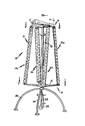
: Referring to Figure 1, crosswind axis turbine 10 is
- . .. .
,
- : ~ :- ~ , . , . , . -
--10--
~ strated as includin(3 blade assembly having four,
vertically disposed wind driven air foil blades 12a,
12~, 12c and 12d pivotally connected between upper and
lower sets of horizontally extending support spokes 14
and 16, respectively, mounted so the blades can turn
independently of each other about vertical axis 19 of
each blade. Spoke sets 14, 16 are f ixed to upper and
lower ends of vertical column 18 rotatably mounted to
support base 2~ so that assembly 11 turns about column
18 in response to wind incident on the assembly. Output
shaft 22 is coaxially mounted in and connected to be
rotatably driven by column 18. Shaft 22 projects below
cvlumn 1~, where it is connected to a suitable driven
mechanism 24 for converting the torque of shaft 22 to
usable power. ~niquely designed blades 12a-12d,
described infra, are mounted to spoke sets 14, 16 to
rotate about two vertical axes, in particular the blades
xotate coaxially with column 18 and about the individual
longitudinal axes 19 thereof. Blades 12a-12d are
constructed so that wind incident there on is channeled
and compressed against each blade for maximum transfer
of wind energy to turbine 10. A unique feedback control
mcchanism 25 responds to wind velocity (i.e. speed and
direction) as detected by a wind vane 26 to
diLferentially adjust the angle of attack of blades 12a-
12d to maintain approximate constant rotational speed
and output power of shaft 22 over a specified range of
wind speeds i.e., between minimum and maximum speeds.
(The blade angle of attack is the angle between the
:~
; 30 direction of the incident wind on a particular blade and
cllord 13, Figuxe 2, of that blade. The blade chord is a
vertically extending plant intersecting the longitudinal
veL~ically extending blade axls about which each blade
.' '; ;' '''- ' . 1,' ' ,"',
: . -
.' ; , . . .
~ 286~
turns and a central apex at the intersection of thebla(3e exterior surfaces).
Uerore describing the structure in detail, a
gelleral overview of the invention is provided by
reference to Figures 1-3 and 7 and 8 wherein wind
velocity vector W is assumed to be displaced from blade
a.ssembly coordinate axis 21' by angle A2. ~ssembly 11
is rota';ed in the counter clockwise direction about axis
36 in response to velocity vector W. Vertical axes 19
of the upper portions of blades 12a and 12c are
respectively displaced counter clockwise and clockwise
a~out axis 21' by the angle A2 while axes 19 of the
upper portions ot blades 12b and 12d are respectively
displaced counter clockwise and clockwise below axis 21'
- 15 b~ the angle A2 ~ 90- Because spoke sets 19 and 16 are
rotatable independently about axis 36 and the radial
! displacement from axis 36 of intersections 1-4 of axes
19 of blades 12a-12d and spoke set 14 is less than that
of the intersections 5-8 of axes 19 of blades 12a-12d
wi~h spoke set 16, lower intersections 5-8 lag behind
in~ersections 1-4 as assembly 11 rotates about axis 36
so the lower blade portion axes are displaced from axis
21' by angles of A3 and (A3 ~ 90), ~here A2.
Each of blades 12a-12d includes a longitudinal
hori~ontal axis 13 that intersects axis 19 and edge 73
(Figure 11) at the intersection of opposite faces of the
70 and 7~' of the blades. As assembly 11 is driven by
wind vector W about axis 36 each of blades 12
continuously turns about the axis 19 thereof so that the
ancJle oE axis 13 oE each blade continuously changes
relati~e to wind vector W i.e., the angle of attack of
each blade.
The angles of attack for blades 12 are also a
; '
., ' ' . , ., ~ .
.
'
39~;
--12--
function oE the magnitude increases, there is a tendency
fOL a greater force to be applied to blades tending to
rotate assembly 11 at higher speeds about axis 36. This
tendency to overcome to a large degree by changing the
angles of attack for blades 12 as they turn about axis
36 so that the surface area of the blades relative to
wincl vector W decreases so there is a reduction in the
force applied by the wind vector to blade assembly 11,
to compensate for the initial tendency of the wind
vector to drive assembly 11 at higher speeds~
In the situation illustrated in Figures 2 and 3 it
is ass~lmed that velocity vector W has a relatively small
~- magnitude and an angle A2 relative to assembly axis 21'
; ! in the plane of spoke set 14 so that the vector is
directed coincident with the axis 21 from axis 36 to
axis 19 of blade 12a, and is directed toward the surface
oE blade 12 a away from axis 36. [~nder the assumed
-~ con(litions, the angles of attack of blades 12a, 12b, 12c
and 12d, i.e.t the angles between axes 13 of blades 12a,
12b, 12c and 12d and vector W in Figure 2, in the plane
of spoke set 14 are respectively approximately 45j 20,
27, and 2. The angles of attack of blades 12a, 12b,
: 12c and 12d in the plane of spoke set 16 lag slightly
.` behind l:hose in the plane of spoke set 14 by the same
approximate 3 angle. The radial positions of
` inl:ersections 1-~ relative to axis 36 are substantially
the same, inside of the radial positions of
~:~ intersections 5-8. At these angles/ maximum force is
imparted by wind vector W to assembly 11 because of the
30 large surface area upwind that blade 12a presents to the
` vector, as well as the substantial but smaller areas
. presented by advancing blade 12b and downwind blade 12c.
Axis 13 o~ retreating blade 12d, however, is almost
.'` " ~ ' ' . '
. : . .- . : , ~ -...... ., .. : .
-13-
aligned with vector W, so blade 12d presents a very
snlall area to vector W and does not introduce
substantial drag.
Now assume that the magnitude of velocity vector W
is substantially larger than previously described and
~ that the angle of the vector is constant. Under these
; cilcumstances, the angles of attack of blades 12a and
12c respectively decrease and increase by relatively
! si~nificant amounts while the angles of attack of blades
12~ and 12d respectively decrease and increase by
rclatively insignificant amounts. The angles of attack
oE blades 12a-12d in the planes of spoke sets 1~ and 16
cllange together because axes 19 are mounted at fixed
radii in spoke sets 14 and 16. The angles oE attack
chan~e in the plane of spoke set 14 because wind vane 26
,~ causes substantial radial shift relative to axis 36 of
control rods 66 connected to pivot controllers 201 and
202 for axes 19 of blades 12a and 12c. Because axes 19
are fixed relative to axis 36, the radial shift of rods
; 20 66 drives pivot controllers 201 and 202. The radius of
control rods 66 connected to blade 12a and 12c are
eEt`ectively decreased and increased respectively; to
` respectively decrease and increase the angle of attack
-` of blades 12a and 12c. There is only a slight change in
the effective radius of control rods 66 respectively
connectod to pivot controllers 203 and 20~ for blades
12b and 12d under the assumed conditions because rods 66
,~ are at Li911t angles to incident wind vector W. Thereby,
the ang,les of attack blades 12b and 12d do not change
substantially. The change in the àngle of attack of
, upwind blade 12a materially reduces the effective area
~' presented b~ upwind blade 12a to vector W; the change in
~ the angle of attack of downwind blade 12c increases the
.,
:':
.
". ' ' '
. . . .. ...
." , ~ ,:
~lZ~3699`rj
dra~J force exerted by blade 12c on assembly 11. The
chall~es in the angles o~ blades 12b and 12d do not
ncLIllally have a substantial effect on the force imparted
by wind vector W on assembly 11. Thus, the tendency for
the increased magnitude of wind vector W to turn
assembly 11 at high speeds is compensated by the changes
in drag angles of blades 12.
- As assembly 11 is turned in response to wind vector
W ~he angles of attack of blades 12 are constantly
changinq. Thus, as assembly 11 turns 90, t~e angles of
attack of blade 12a gradually chan~es from the position
illustrated for i~ in Figures 2 and 3 to the position
strated in Figures ~ and 3 for blade 12b. As the
diLection of wind velocity vector W changes, wind vane
26 controls the angles of blade axes 13 relative to
assembly axis 21' so that the blade angles of attack
remain constant relative to the direction of wind vector
W for the same angular relationship of radius 21 and the
wind vector direction. Thus, e.g., for low magnitude
wind v~ctors, axis 13 of blade 12a is 45 displaced from
radius 21 when radius 21 is aligned with wind vector W.
The mechanism for attaining these results and other
improveloents is now described in detail.
Support base 20, as best illustrated in Figure 1,
includes a pair of tubular support legs 30 each having a
semiciLcular configuration in the vertical plane to
elevate blades 12a-12d above the ground or other
gellerally horizontal wind impervious surface to obtain
maximum exposure of the blades to the wind, while
presenting a narrow, rounded wind profile for improved
stability. Support legs 30 are orthogonally arranged
and fixedly mounted on cylindrical support tube 32
(Fiyure 9), which projects vertically upward from the
!
.
', '
' ' ' ' ' ~, , ' ' . ' ' : ,
~L2~69
-15-
legs and is coaxially mounted in the lower end of hollow
cyliildri~al column 18. Column 18 is rotatably supported
on ~ube 32 by thrust bearing 34 and yoke 35. Output
shaLt 2~ extends coaxially in support tube 32 along
ver~ical axis 36 of column 18 and is rotatably supported
by axial bearing 38, located in the upper end of the
support t~be~ In response to blades 12 rotating, torque
is ~ransmitted from rotating column 18 to output sha~t
22 through circular coupling plate 40, horizontally
fixed in the column by bolts 42. The upper end of shaft
22 is Eixedly connected to plate 40 in central opening
43 o~ the plate. As illustrated in Figures 1 and 9,
low~r spoke set 16 includes four mutually orthogonal,
identical hollow spokes 16' extending horizontally and
radially from column 18. Each spoke 16' is fixed to the
low--r end of column 18 by bolts 44.
Each of spokes 16' is shaped in cross section as an
airfoil (Eigure 9~), preferably along the entire length
the~eof, to enhance air flow, by p~h ing air upwardly
into the interior of blade assembly 11. The air ~oved
into the interior of as~embly 11 helps to create a
~cr~a~ in yelQcity: in the assembly interior to
enhance the flow of wiad against the blades 12.
Spherical bearing 45, mounted in distal end 46 of each
spoke 16', receives the lower end of one oE each of
~lades 12 enablin~ the blades to ~otate about
longitudinal axis 19 thereof to change the blades angle
of a~tack to that wind force imparted to each blade is
maxifni~ed.
Uppcr spoke set 14 also includes fo~r identical
hollow spokes 14' extending horizontally radially from
col~ n la and spaced 90 from each other. ~ach spoke
14' is Eixed to the upper end of column 18 by L-shaped
': ;
- : '
6~39~
-16-
~)r~ckets 48. ~s illustrated in Figures 2 and 3r
corre~ponding pair3 of spoke~ 14', 16' are not
vcrtically aligned; instead longitudinal axis 21 of each
upper spoke is circumferentially advanced with respect
~o longitudinal axis 21a of each lower spoke so that
each blade axis 19 is preferably tilted approximately 3
in the direction of rotation.
~ ach of blades 12a-12d is of identical construction
and includes a molded structurel~. strqng - outer skin
layer 50 (Figure 11), defining opposite longitudinally
extending surfaces 52a and 52b exposed to the wind.
Mass 34 of low density filler, such as expansion Eoam,
is disposed between surfaces 52a, 52b to impart
structural rigidity to the blades. Rigidity is also
ellhanced by shaft 56 extending longitudinally through
tlle blade to define blade axis 19.
Upper and lower ends 56a and 56b o~ shaft 56
project outwardly through spoiler end panels 58
respectively located at opposite ends o~ each blade.
Lo~Jer shaft end 56b is received in spherical bearing 45
(l;`igure 9) provided in each lower spoke 16' as mentioned
above, ~pper shaft end 56a extends through axial
bearing 60 mounted in the bottom and adjacent the outer
e;ld of each spoke 14'. Pinion 62 fixed to upper shaft
end 5~a is thereby located in each spoke 14' to mesh
with a rack 54 attached to free end 66a of connecting
rod 66 that extends longitudinally through spoke 14'.
~rhe opposite end 66b of rod 66 is connected to circular
connecting plate 68 (Figures 4 and 7) to control
adjustment of the angle of attack o~ each blade as
assembly 11 rota~es about column 18 as described infra.
a;:ach blade 12a-12b has a teardrop cross section
defined by a ~eries of trouqhs 70 and 70' (Figures 11,
: '
., , ~' ' ~
. `;'
: . -
~286~S
--17--
12, and 12A) respectively formed equispaced and parallel
to eac~ other between crests 71' along the entire blade
lengl:h on both surfaces 52a and 52b. Mating t:roughs 70,
70' on vyposite surfaces 52a and S2b are longitudinally
5 aligned with each other to intersect trailing edge 72 as
a common longitudinal location and are tapered to have
decreasing width and depth as they extend from edge 72
to edge 73 in the direction of 73. The taper extends
across approximately 80% of the uniform blade width
lO bet~een edges 72 and 73. The bottom of each trough 70
and 70' are staggered with respect to each other along
the blade length so that each trough defines and airfoil
shaped blade segment i.n cross section. In this manner,
trc,ughs 70 reduce the speed of wind striking high
15 pr~ssure blade surfaces 52a or 52b, whichever surface is
exposed directly to the wind as occurs particularly when
the blades are in the upwind position of blade 12a
(,urface 52a) or downwind position of blade 12c (surface
52~). 'rhe wind incident on the surface 52a or 52b
O divergec; across the entire surface an~ëcelerates as it
flows smoothly across the concave surface of each trough
towards trailing edge 72, to transfer a greater amount
oE ~ind energy to the blades. S imultaneously, in the
upwind position of blade 12a, crests 71' located on the
25 low pressure si~e or surface 52b opposite troughs 70
cr.ate a high pressure section opposite the high
prcssurc section created by troughs 70 so that the
trailing vortex drag of the merging high and low
prcssurc sides is substantially reduces, as also arms on
30 the low pressure surface 52a when the blades are in the
; ! downwind position of blade 12c.
When the blades travel into the direct upwind
E-osition of blade 12d in Figure 2, trough 70' on high
-. .
: . .
'
-. ~ . ,
.: :
3L2~699~
-18-
prossuro surface 52b primarily coact with tro~ghs 70 onlow pressure surface 52a to reduce vortex drag since the
blades in this position are generally aligned with the
wil~d. When the blades are in the position of blade 12b
in FiguLe 2, the troughs 70 on hiyh pressure surfa~e 52a
naLrow in the downwind direction, causing wind to
colllpress and accelerate against tlle downwind leading
edge 73 of the blade to rotate the blade in the
dire~tion oE rotation.
To minimize the total surface area of troughs 70
and crests 71 (defined by ~roughs 70') directly
cha~ elillg wind flow across the width of ea~h blade 12a-
12d and ~hereby minimize skin friction, the preferred
rallge oE the ratio of width W to depth D of each trough
1, is approximately 4:1 to 8:1. For optimal results,
however, a preferred ratio W:D is abut 6:1.
As best illustrated in Figure 1 for blades 12a and
l~c, blades 12a-12d are mounted on spokes 14' and 16' so
the upper portion of each blade is closer to column 18
than the lower portion of the blade wherein blade
assembly 11 is similar to a truncated cone having a
lower base layer than an upper base. Because of this
truncated cone arrangement, the pair of downwind blades
draws air into the interior of blade assembly 11 through
the upper section of the assembly. The air drawn into
the upper part of assembly 18 spirals downwardly about
column 18 to combine with air Elowing upwardly into the
assembly through air foil shaped spokes 16'. The
upwardly and do~-nwardly directed air currents meet in
~he intericr of assembly 11 where they combine to exit
~r~m approximately the lower two thirds of the assembly
(l.e., in the space between spokes 16' and two thirds of
- the way up to spokes lg'). The exiting air current
.' : , ` ' . ,
~ . . - ~ ;
~2~699~;
-19--
fl-ws in the same general direction as the incident
~ind. With this arrangement, a large volute volume of
air is swirled and accelerated in less than the total
interior volume (i.e.., the lower two thirds portion) of
assembly 11, th~reby imparting additional wind energy to
b]ades 12a-12d. The accelerated, swirliny air flow
obtained with inclined blades 12a-12d also promotes
lalninar flow conditions in the interior of assembly 11
without creatiny a standing wave effect (i.e. wind
repeatedly reflecting off the blades in the assembly
interior, without escaping from the interior; the
`~ standiny wave tends to cause turbulence and impair blade
eEficiency).
o obtain the accelerated swirling air flow in
asiembly 11 as described above, the ratio of the
diameter of upper spoke set 14 to the diameter of lower
sp(jke set 16 is preferably about 2:3 althouyh the ratio
c.-ln vary from between appro~imately 1:2 to 4:5; the
he~i(3ht of column 18 is preferably equal to the sum of
the diameters of upper and lower spoke sets 14, 16 but
can be as small as the diameter oE the lower spoke set.
i';h the aforesaid preferred ratios, blades 12a-12d are
positioned on spokes 19', 16' so axis 19 of each blade
is inclined from the vertical towards central axis 36 by
about 6 (inclination angle Al, Fiyure 9); while being
advanced about 3 (blade advance angle A2) in the
difection of rotation, as discussed above. ~lowever,
wh~ll the ratio of diameters of the upper and lower
sl)okes 1~' and 16' as well as the height of column 18,
is varied within the above ranges, I have found that the
followiny equations can be used to calculate inclination
angles Al and blade advance angle A2, in degrees, to
within a 1 accuracy:
;'~ .
,,
. - :
-
1~ ~6~95
-20-
o B-T
1 2~l
[ ( I )~
where: H = height of column 18
B = diameter of lower spoke set 16
T = diameter of upper spoke set 14
Sillce blade axis 19 is tilted preferably about 3
in the direction of blade rotation and preerably 6
towards axis 36 as mentioned above, it can be seen from
Fi~Jures 2 and 3 that the angle of attack of each blade
12a-12d to the wind increases as the height of each
blade increases toward upper spoke set 14 (i.e., B>B'
in Figure 2 and 3). This variation in blade attack
angle is necessary due to the lower tangential velocity
! of smaller upper spokes 14' relative to the lower spokes
16' during rotation of assembly 11 about column 18. In
this manner, each section along the entire length of
blades 12a-12d is respectively maintained at a favorable
an~le or attack between B and B' to optimize blade
efliciencyL Furthermore, to produce maximum torque with
turbine 10, I have found that the following formula can
be used to calculate the width (W) of each blade 12a-
12d:
W = 0.0533~B
Os~illation of each blade 12a-12d about blade axis
19 thereof is controlled by a rack and pinion assembly
comprised of rack 64 pivotally supported in the upper
spokes on pillow blocks 65 or slider wheel 65' at outer
;' ,. .
~2~9g~
-21-
~n~, G5a of each connecting rod 66; racks 64 respectively
me llwi~:h pinions 62 provided at upper end 56a'of each
blade. ~s illustrated in Figures 4 and 7, three of
col-lnecting rods 66 are pivot:ally mounted to circular
conllecting plate 68, located in the upper portion of
column 18, by spherical bearings 75 peripherally
disposed on the plate 90 from each other. The inner
end of the remaining connectiny rod 66', secured to
blade 12a, is fixedly attached to the periphery oE plate
6~ at a location 90 from adjacent bearing 75. Thereby
rod~ 65 are free to pivot about fixed points adjacent
tl;-~ periphery plate 68 while rod 66' always remains
fii:ed in position so the longitudinal axis thereof
inl,ersecls axis 36.
`~ ~, 15 Spherical bearing 77, mounted in the center of
plate 6a, receive~ an upper vertical section 100 of a
control shaft 80 that projects through upper end 82 of
`-` column 18, covered by a flexible weather seal 84. Wind
`, vane 2h, fixed to the upper end of shaft 80 above upper
`- 20 sp~ke set 14, adjusts the pitch of blades 12a-12d
th~vugh the asseinblies including racks 64 and pinions 62
in response to changes in wind velocity, as described
below. 5top 8G, fixed to shaft section 100 supports
bearing 77 and thereby plate 68 in a horizontal plane
immediately below connecting rods 66.
Win-J vane 26, as best illustrated in Figures 13-15,
- is a horizontally extending structure having a low,
relatively thick counterweight profiled forward segment
~;~ 88 and a thin relatively high rearward segment 90.
30 Segment3 88, 90 located on opposite sides of upper
see~ion 100 of control shaft 80 (Figure 4), have the
same weight for ilnproved stability. Fixed to vertical
~ac~92 oC rear segment 90 is air scoop 94 having curved
; , ' . '
.
, '
.~ .
, ~ .
3699~;
-22-
wall 95 defining large upwind opening 96 and a smaller
do~nwind opening 97. As wind passes around profiled
foLward segmellt 88 and enters upwind opening 96, wall 95
tapered towards rear opening 97, causes the passing wind
~- 5 ~o strike vertical face 92, to turn vane 26 into
~- alignment with the wind and rotate control assembly 80.
Control assembly 80, Eorming wind speed and
; di~ection detector of feedback control mechanism 25,
collsti~utes an important feature o~ the invention. ~s
- lO illustrated in Figure 4, assembly ~0 includes shaft 81
tl~at is located primarily in column 18 and has straight
vertically extending upper and intermediate segments 100
and 0].8 connected to each other by inclined segment 104.
~puer section 100 extends upwardly through center
b~aring 77 so it supports vane 26 above blade assembly
. Rod 81 includes portion 106, projecting downwardly
1rom and inclined relative to segment 108. Shaft
por~ions 100, 104, 106, and 108 are coplanar, with
veL~ical portion 108 radially offset (i.e., non-coaxial)
with respect to section 100. Sleeve 110, fixed to
o.Eset shaft portion 108, includes an elongated
horizontal passage 112 containing horizontal pin 114,
haviny one end attached to an inner surface of sleeve
bearing 115. Bearing 115 is coaxial with axis 36 and is
rol:atably mounte~ in the upper portion of column 18 by
pairs of upper and lower axially spaced bearings 117
- .
located between the facing outer walls of bearing sleeve
~; 115 and inner surfaces o~ column 18. Vertically
e;~tending seats 119 and 122, respectively at the lower
ellds oE inclined shaft por-tion 106 and sleeve 115
cap~ure opposi~e ends of compression spring 120, having
a horizontal axis to provide a counter force for the
~endency o~ shaft 81 to rock about pin 114 in response -~
' ':
".
' ',~'' ;-
'
. ';
, ' " ; . . ...
.
. . - ' :
~2~69g~
23
to vane 26 tilting as a function of the speed of wind
incident on the vane. When the wind calms, spring 120
stabilizes vane 26 in the horizontal plane. The pivot
angle of rod 81 relative to pin 114 controls radial
displacement on control plate 68 relative to axis 36
of column 18, to control the angular position of each
blade 12a-12d about the axis thereof at the different
angles about axis 36.
To understand the operation assume that each blade
12a-12d is mounted to assume a particular angle of
attack relative to the incident wind (see Figure 7)
which is aligned with the axis of spoke 16 carrying
blade 12a. Thereby blades 12a and 12c are
- respectively in upwind and downwind positions, while
blades 12b and 12d are in cross wind positions. Blade
12a is rotated by connecting rod 6, rack 64 and pinion
62 connected to it so it has a favourable wind angle
of attack, depending upon wind speed, of approximately
45, the approximate angle where maximum wind energy
` 20 is imparted to rotate the blades. As blade 12a
rotates 90 about column axis 36 into the downwind
position occupied by blade 12b in Figure 7, the
effective wind striking exposed klade surface 52a
: causes pinion 62 to rotate in meshing engagement with
` 25 the teeth of rack 64 (pivotally supported within each
spoke 14l by a pillow block 65 or grooved control
wheel 65') so that blade 12a rotates about axis 19 in
a controlled manner to assume a lesser angle of
attack of about 20 allowing the blade to
continue imparting rotative torque to the
-` turbine structure without causing excessive wind
resistance. As blade 12a continue~ travelling
downwind into the position occupied by blade 12c in
; Figure 7, pinion 62 continues to rotate while
moving rack 64 so that the blade assumes
. :
.
:
. ~ .
-24-
;
(
an an(31e oE attack of about 27 allowiny wind to
slllo~ ly exit from the interior oE turbine 10. ~s blade
l~a then rotates in the upwind direction into the
J~o;i~iOn of blade 12d in Figure 7, the angle of attack
bccomes about 2 so that the blade is virtually
tr~veling parallel to the wind to minimize resistance.
ilnultalleously, of course, connecting rods 66 which are
in,~rc~ ected through plate 68 move radially to adjust
~- the blacle angle positions of the other blades 12b-12c
0 d~lL ing travel thereof into the aEoresaid positions.
OfEset shaft portions 104, 106 and 108 oE control
shaEt 81, being pivotal in vertical plane 125 about pin
; 11~, advantageously allow radial placement of upper
sh.ft portion 100 and thereby control plate 68 so that
~he eEEective length of each connecting rod 66
col--s.antly changes during blade rotation about central
a~is 36 due to the aforesaid movement of racks 64 caused
b~ pinions 62. By experimentation, it has been found
tha~ ofEset portions 104, 106 and 108 are mounted so as
to be oEEset from the forward or upwind segment 88 of
valle 26 in the direction of rotation by an angle 0 of
between 30 and 40, preferably 35. It has been
dls~overed that this mounting relationship uniquely
op~Lates to create a favorable attack angle of blades
12a-I2d for a longer duration during the downwind phase
c~f bla-le travel, enabling turbine 10 to derive more
uo~er Erom this phase of rotation about axis 36. This
arrangement also ~ermits blades 12a-12d to rotate about
~; column 18 at a tangential linear velocity of between 2.3
an-i 2.6 ~imes greater than wind speed to obtain maximum
.. . .
power output.
~ earings 75, 77 maintain connecting plate 68 in
sul/stall~ially the same horizo4tal plane as the
~.
:
,
'
!
.. ..
~ . . . .
- l~r~ s
--2~--
loll;Ji-udinal axis oE connecting rods 66 continuously
change in the aforesaid manner as the blade attack
an~les change in the aforesaid manner duriny rotation
about axis 36. Furthermore, bearings 75, 77 as well as
tlle aforesaid rack and pinion connections and easy
pivotiny movement obtained with the offset control shaft
~0 within cylindrical bearin~ 115 provide low friction,
smooth translational movement of connecting rods 66.
Wind vane 26 uniquely operates as a static wind
load control through the aEoresaid rack and pinion
c~nllections 201-204 and control sha~t 80 to provide
further blade adjusl:ment in response to changes in wind
sp~ ed or direction. For example, should wind direction
change ~rom W to W' in Figure 8, rotation of vane 26
in~o realignment with the wind causes corresponding
rotatioll of shaft section 100 and thereby pivotal
-~ Inovement oE ofEset portion 108 so that plate 68 moves
radially to reorient the blade angles. Vane 26 rocks
ba~:l;ward about pin 114 in response to an inc~eased wind
low entering air scoop 94, (see Figures 6A and 6s)~
causing plate 68 to translate in the downwind direction
by the action oE shaft section 100 acting against the
ylate. Connecting rods 66 between plate 68 and blades
12a-12d are transIated causing the effective radii of
inl:crsections 1-4 and the attack angles oE blades 12a-
; lZd to change, as described supra, so that the blades do
nul: oveLspeed. Thus constant speed and power output oE --
bl~l:les 12a-12d are maintained while excessive stress and
possibie damage to turbine 10 is avoided.
Sl~ould excessive wind conditions develop (e.g.,
}:urricane wînd Eorce), racks 69 and pinions 62 respond t
control shaft 80 to adjust the blade attack angles to
~` turn l~lades 12a-12d so axes 13 are aligned with wind
~, .
. -- .
:' I
.
.. .. .
, ~, ', , . ' . , ' ', :
. . . .: ., , ~ -
. . . . ...
~2 ~69
-26-
ve~ocity vector W to stop turbine 10. The aEoresaid
arLangelllcnt also adjusts the blade angles of attack when
assembly 11 has been braked, to dump hiyh wind loads
Lrom blades 12a-12d, thereby avoiding damage to the
~` 5 blade s~ructures.
A second embodiment oE control mechanism 25 for
contl:olling the blade angles of attack in response to
`~ challges in wind speed and direction includes a pair of
cylindrical weights 120 resp~ectively located inside of
two diametrically opposed lower spokes 16'. ~s
; i]]ustr.lted in Figure 9, each cylindrical weight 120 is
sli~ably mounted between pairs of upper and lower roller
bcarings 122 and 124, respectively carried in
sclnicylindrical channels 126 of bearing support members
15 12-1 and 127a. Roller bearings 122, 124 engage
circumEerential surfaces of weights 120 to define a
horizontal slide path to enable the weights to move
raclially with respect to column 18 through spokes 16' in
response to variations in centrific force caused by
changes in wind velocity acting on blades 12a-12d.
T~lo cables 128, respectively attached to the faces
`~ oE weiyhts 120 adjacent column I8, pass around pulleys
~ 130, mounted on yoke 35 and extend vertically upward
.~ .
bet~een column 18 and support shaft 32, for attachment
to a pair of vertically extending connecting rods 132.
- r~Ods 132 are sli~ably disposed in apertures 134 of
coupling plate 40; upper ends of the rods are connected
to hori~ontal cross plate 136, located above the
coupling plate. Connecting rod 137, fixed to the center
30 oE plate 136, extends upwardly along central axis 36.
5he upper end of rod 137 passes through opening 138 in
pla~e 139 at the bottom o hollow, square control tube
14~ and is connectcd to throwout bearing 142, mounted on
~ I
:`~
; '
:-' ' ' ~
,
.~ . , . ~, ;.
~28~995
-27-
plite 139. Bearing 142 prevents rotation oE control
tu!e 140 with rod 137 and weights 120 about the column
36 aY~is during blade rotation about column 18. Flexible
oil ~ube 141 extends through shaft 22 to supply
lu~ricant from a source (not shown) to bearing 142.
Tube 140 is mounted directly below and coaxially
wi~ll cylindrical bearing 115 ~surrounding oEfset shaft
po;~ion 108) to receive the lower inclined shaft portion
106 between side walls 144. Tube 140 includes side
~ialls 144 one oE which has an opening 145 through which
thc lower end 118 of shaEt portion 106 projects. Roller
~-14~, ro~atably mounted to upper edge 148 of opening 145,
- ~rolls orl straight upper inclined surface 150 of shaft
:.............. pOL~iOn 106 to vary the position o~ offset portion 108
in the manner described below. Upper end 153 of L~
llaped guide member 152 is fixed to the inner surface of
cyllnder 115 to extend downwardly to be received between
and slide along side walls 144 to maintain square tube
14~d in vertical, coaxial alignment with the cylinder.
~;;20 Pin 114 is fixed to the upper portion o~ guide member
152. Compression spring 12~ is horizontally disposed in
tul,c 14~ between lower end 118 of inclined portion 106
an-l sea. 122', abutting against the lower edye on the
inner surface of the guide member.
Wi~h the arrangement of Figure 9, weights 120 slide
radially in spokes 16, so the weights move away from
column 18 when the wind speed acting on blades 12a-12d
in-~reases. The outward movement oE weights 120 draws
cablcs 128 down to exert a downward force on connecting
! 30 ro~ 137 throughlrod 132 and cross plate 136 to pull
;~ s~ are tube 140 (which does not rotate with connecting
rocl 139 ~y virtue oE throwout bearing 132). ~s tube 140
moves dvwn, roller 146 exerts a force on inclined
-
.' . ,- . .; ' ~
,.... .
~:13qEig9~
28
surface 150 so that offset shaft portion 108 pivots on
pin 114 to increase the attack angles of blades 12a-
12d in the manner described above. Spring 155,
connecting plate 136 to coupling plate 40, is thereby
loaded in compression so that weights 120 are
retracted by the force of spring 155 when wind speed
decreases, allowing square tube 140 and roller 146 to
move up along surface 150 to restore the blade angles.
Weights 120 in the second embodiment are preferred
for use instead of wind vane 26 in large
installations. However, weights 120 can be used in
- combination with vane 26 to vary the blade attack
angles in the aforesaid manner. When using weights
-; 120, it will be recognized that they tend to move
radially back and forth about an equilibrium point
-~ within spokes 16' as the weights adjust the blade
angles of attack in response to changes in wind speed
and direction, since, after initial adjustment occurs
` in the aforesaid manner, the weights tend to move
-~ 20 radially inward (if wind speed has increased or wind
direction has changed counterclockwise in Figure 2) in
~` response to a lowering of centrifugal force acting on
`~ the blades ~restored to constant velocity movement).
:-
~ ' '.
', ' " ''