Note: Descriptions are shown in the official language in which they were submitted.
~ 3~ 72~32-12
T~UNNIO~ IY~ DALL vAL.~
Back~round of the Invention
This invention relates to ball valves ancl, more
particularly, to trunnion type ball valves.
Trunnion type ball valves are well known and
generally comprise a valve body having inlet and outlet flow
passages and a central cavity for receiving a ball valve
member. The ball valve member is formed with a bore and a pair
of trunnions extending from opposite sides of the ball along a
line generally transverse to the bore. By use of the
trunnions, the ball valve is rotatably mounted in the central
cavity so that it rotates between an open position where the
bore is aligned with the passages and a closed position where
the ball valve surface extends across the flow passages.
Between the ball valve and the portions of the body surrounding
the passages, there is located a valve seat member that
cooperates with the ball valve surface to prevent flow of fluid
through the valve.
Most ball valves of the trunnion type generally
include some biasing arrangement for compressing the valve
seats against the ball valve member to provide a fluid tight
seal between the seats and the ball valve surface when the
valve is in its closed position. These biasing arrangements
commonly provide for the cornpressive force even in the open
position of the ball valve. This has resulted in extensive
wear on the valve seat or on the ball valve surface during the
opening and closing movement of the ball valve because of the
compressive force. After a while this wear causes the valves
to leak and require frequent replacement of the ball valve
and/or the valve seats. In addition, use of the biasing
mechanism in the first instance adds to the expense of the ball
~2~3-~ 72~32-12
valve and these mechanisms are another source of fai]ure that
necessitates replacement. This, of course, adds to the
manufacturing and maintenance costs of the valve.
~ ne attempt to avoid the use of the biasing mechanism
is disclosed in U.S. Patent No. 3,410,523 issued to W. Kelly et
al on November 12, 1968. In the Kelly patent, there is
disclosed a trunnion type ball valve wherein the valve seat
faces are not coaxial with the axis of the inlet and outlet
flow passages and wherein the ball valve is not a true
spherical surface. The valve seat members are, in fact, offset
to either side of the axis of the flow passages to cooperate
with opposed eccentric curved portions of the eccentrically
shaped ball valve member. With the ball valve disclosed in the
Kelly patent, there is no loading or compression of the valve
seat in the open position of the ball valve and only a light
loading in the closed position. With this type of arrangement,
the light loading in the closed position may be insufficient to
establish a satisfactory seal and may not satisEactorily
eliminate leakage. In addition, the cost of machining the
eccentric shape of the ball valve member adds to the
manufacturing cost.
Another problem associated with the ball valve dis-
closed in the Kelly patent results from the self-compensating
feature wherein wear of the valve seats is accommodated by
merely turning the ball valve member an additional one degree
(1) to three degrees
t3) to obtain the clesired seating. This means that the valve
cannot be usecl wlth conventional valve actuators which operate
to rotate the valve throuyh only ninety degrees (90) from the
closed to the open position. ~onventlonal valve actuators are
not torque clepenclent and ~ould not permit the self-compensation
feature to be effectuated.
Summary of the Invention
Acc~ordingly, it is an object of this invention to
provide a ball valve that eliminates the need for a biasing
mechanism for the valve seat.
The invention provides a ball valve comprising a
valve body having flow passages formed therein and a cavity
formed therebetween, a ball valve member having a bore
extending therethrough, said ball valve member being mounted in
said cavity for rotation between open ancl closed positions, a
pair of valve seat members located in said cavity between said
valve body member and said ball valve, said valve seat members
being movable relative to said valve body member, said ball
valve member havlng a surface configuration for exerting
substantially no load on said valve seat members in its open
position and for compressing said valve seat member agains-t
said valve body member in the closed position, said surface
configuration including flrst surface portions adjacent each
end of said bore, said first surface portions being generally
complemen-tary to the adjacent surface of ~aid valve seat
members and a second surface portion of increasing projection
extendiny between said first suriace portions, said first
surface portions being frusto-conical surfaces and said second
surface portion belng generally spherical.
The disclosed trunnion type ball valve eliminates the
need ~or a biasing mechanism for the valve seat and provides
~7~3~
for a satisfactory compression loading and thus sea:lincJ between
the ball member ancl the valve seat i.n the ~losed positlon. It
comprises a top entry trunnion -type oi ball valve that ls
plastic llned so that it is usable with corrosive fluids. The
ball valve is relatively simple, inexpensive and easy to
manufacture and maintain.
The ball valve member has a pair of trunnions
extending from opposite sides of the valve member surface. By
use of the trunnions, the ball valve member is rotatably
mounted in the cavity for rotation between open and closed
positions. The pair of valve seat members are movable relative
to the valve
~a
~37~35i
72~32-12
body. The ball valve member has a surface conflguration that
exerts substantially no load on the valve seat members in its
open position and that compresses the valve seat member
against the valve body member in its ~losed position. Prefer-
ably, the surface configuration causes limited movement of the
valve seat members in the direction of its movement when mov-
ing between the open and closed position and then causes the
valve seat members to move back in the opposite direction un-
til they center themselves with respect to the flow passages.
BRIEF DESCRIPTION OF THE DRAWINGS
For a better understanding of the invention, refer-
ence is made to the following detailed description of a pre-
ferred embodiment with reference to the figures of the accom-
panying drawing, in which:
Figure 1 is a section view through a ball valve in
accordance with this invention;
Figure 2 is an enlarged view of one of the valve
seats illustrated in Figure 1; and
Figures 3 through 5 are section views taken
generally through the line 3-3 of Figure 1 illustrating the
open position of the valve, an intermediate position of the
valve and the closed position of the valve, respectively.
DETAILED DESCRIPTION OF A PREFERRED EMBODIMENT
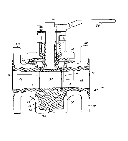
In Fig. 1 of the drawing, there is disclosed a ball
valve 10 including a valve body 12, a ball valve member 14 and
a pair of valve seats 16,16. The ball valve 10 disclosed here
is of the type generally referred to as a "top entry" ball
valve. In addition, the valve body 12 and ball valve member
14 are lined with a plastic material along the surfaces
03~
72432-l2
exposed to fluid so that it is usable with corrosive fluids.
The plas~ic lining is clearly denoted in the drawing. The
plastic lining can be applied to the valve body 12 and ball
valve member 14 in accordance with the techniques disclosed in
U.S. Patent No. 3,407,838 issued to ~l.W.
- 4a~
3~i
,
Boteler on October 19, 1968. It should be understood
that the plas~ic lining is not necessary for the
practice of the invention~
The valve body 12 is made of metal by conventional
casting techniques and the plastic lining is applied as
noted above. It includes a pair of aligned flow passages
18,18 which are used for the inlet and outlet flow of
fluid. Adjacent the open end of each passage 18 there
is formed a flange 20 used to secure the valve to mating
flanges formed on flow pipes. Between the inner ends of
the flow passages 18,18, the valve body 12 is formed
with a central cavity 22 having a generally spherical
shape. The configuration of the central cavity 22 will
be explained in more detail hereinafter, but it should
be noted that the size and configuration of the cavity
- is such that it does not restrain movem~nt of ~h.e ~al~.re
seats 16,16 and that the valve seats can move relative
to the valve body over at least a limited distance.
Extending from the bottom of the central cavity 22, as
viewed in the drawng, is a generally cylindrical cavity
24 and opposite this cylindrical cavity is a somewhat
enlarged opening 26 that permits entry of the ball valve
member 14 and the valve seats 16,16 during assembly of
the valve. After assembly, a cover 28 is placed over
the opening 26 and secured to the body member 12 by
suitable fasteners so that the body member is closed
except for the open end of the passages 18,18. The
cover 28 is also plastic lined as shown in Fig~ 1.
The ball valve member 16 includes a ball portion
30 formed with a bore 32 extending therethrough. In
use, the bore 32 aligns with the passages 18,18 to allow
the flow of fluid through the valve. Extending from the
outer surface of the ball portion 30 along a line
generally perpendicular to the bore 32 is a trunnion 34
3s which is received in the cylindrical cavity 24 and rests
on the bottom wall thereof; extending along this same
line and opposite the trunnion 32 is a shaft 36 which
--5--
~87~35 72432 12
extends axially through the opening 26 and the cover 2~. As
is usual, bearings and packings are provided between the cover
28 and shaft 36 and a handle 38 is attached to the projecting
end oE the shaEt Eor use in rotating the ball valve member.
It can be seen that the ball valve member 14 can be rotated
between the open position described above, through about 90,
to a closed position (see Fig. 5) wherein the outer surEace of
the ball portion 30 extends across the valve seats 16,16 and
their adjacent passages 18,18.
The valve seats 16,16 are generally annular members
made of a somewhat resilient material, for example~ fiberglass
reinforced TFE plastic. The inner diameter of each of the
annular valve seats 16 is substantially equal to the diameter
of the passages 18,18. In as much as the valve seats 16,16
are the same, only one need be described and such description
is made with reEerence to Fig. 2. One side of the valve seat
16 is formed with a generally flat bearing surEace 40 which
extends from the inner periphery of the annular member to a
point intermediate the inner and outer peripheries. The
opposite side of the annular member is formed with a frusto-
concial sealing surface 42, that is, the surface 42 extends at
an acute angle to the bearing surface 40. In the preferred
embodiment disclosed herein, the angle between the sealing
surface 42 and the bearing surface 40 is approximately 30.
An inclined surface 44 extends from the radially outer end of
the bearing surface 40 to the outer periphery of the annular
member so that it too forms an acute angle with the bearing
surface. In this embodiment, the exterior angle between these
surfaces is approximately 45 so that the interior angle is
approximately 135.
-- 6 --
72432-12
As best seen ln Figs. 3 through 5 r the central
cavity 22 formed in the body member 12 i9 formed with a pair
of flat surfaces 46,46 wh.ich surround the passages 18,18 and
which are connected by generally spherical surfaces 4~
The flat bearing surfaces 40,40 of the valve seats 16,16 are
adjacent these flat surfaces 46,46. The width, that is, the
extent of the flat surfaces as viewed from the top is just
slightly larger than the diameter defined by the outer
periphery of the flat bearing surfaces 40,40 so that the valve
seats 16,16 can move slightly in the circumferential direction
of the ball portion 30. As seen in Fig. 1, the length of the
flat surfaces, that is, the distance between the open end of
opening 26 and the intersection between the central cavity 22
and the cylindrical recess 24 is also larger than the inner
and outer diameter of the annular member. Thus, the valve
seats 16,16 are unrestrained by the valve body 12 so that they
would be movable therein except for the interaction with ball
portion 30.
The ball portion 30 of the ball valve member 16 has
the general configuration described in U.S. Patent No.
4,147,326 issued April 3, 197g to A. Natalizia. As best seen
in Figs. 3 through 5, the outer surface of the ball portion 30
includes first surface portions 50,50 in the :Eorm of frusto-
conical surfaces which extend at an angle complementary to the
sealing surface 42 on the valve seats. These first surface
portions 50,50 extend around the open ends of the bore 32 so
that in the open position of the valve, the first surface
portions are adjacent the sealing surfaces. Because the angle
on the surfaces 50 is the same as the angle on the sealing
surfaces 42, and because of the dimensions selected for the
--I _
~2~35 72~32-12
ball, seat and cavity, there is no load exerted between the
ball valve and the valve seats in the open position of the
valve. In ef:Eect, the valve seats are trapped between the
ball valve member and the valve body but they are not clamped
in place. Connecting the first or frusto-conical surfaces
50,50 is a second surface portion 52 which is generally
spherical and of such a diameter that it loads the valve seats
16,16 in compression when the ball valve member is in the
closed
- 7a -
~L2~
position illustrated in Fig. 5O In this position, the
spherical surface 52 clamps the valve seats 16 against
the flat surfaces 46,46 and then compresses the material
of the valve seats so that a tight sealing engagement is
S provi~ed between the sealing surfaces 42 and the
spherical surface 52. It should be understood that
other suitable configurations could be utili~ed for the-
ball portion 30 to accomplish the functions performed,
e~g., the ball portion 30 could be elliptical and the
first and second portions described above would
correspond to portions with different radii along the
ellipse.
During movement of the ball valve member 14
between its open and closed positions, the valve seats
16,16 are ~oved through a limited distance in the same
- dir~tl~n ?S th~ b~ll ~^r~-or. 3n. ~5 ~T~vi~lT~L ls
illustrated in Fig. 4 showing the movement of the valve
seats 16,16 as the ball valve member 14 moves from its
open to closed position. When the inclined surfaces 44
of the valve seats 16 butt against the spherical
surfaces 48 in the central cavity 22, further movement
is prevented and continued movement of the ball valve
member causes the valve seats to snap back in the
opposite direction until they are centered with respect
to the passages 18,18. During this movement, very low
loading is maintained on the seat throughout most of the
90 rotation. As the valve is finally closing, and
the seats are centered, a high compressive load is
effected to provide an effective sealing. The trunnion
34 and valve stem 36 distribute the loads evenly over
the entire bearing area and such even distribution is,
of course, of extreme importance in plastic lined valves
which cannot withstand t-he same high loading as metalO
The circumferential movement of the valve seats
16,16 need not be stopped by the spherical surfaces 48.
If desired, the flat surfaces 46,46 can be larger and
the ball portion 30 would snap the seats back to center
~L~8r7~3~
when the ball diameter crosses a certain point.
To assemble the ball valve member 14 and valve
seats 16,16 in the valve body 12~ either during an
initial assembly or replacement, the cover 28 is, of
course, removed and the ball valve member and seats are
inserted through the opening 26 into the central ca~ity
22 with the trunnion 34 extending into the cylindrical -
cavity 24. The tolerances are such that the insertion
is relatively easy so long as the insertion is made with
the valve in the open position.
While in the foregoing a preferred embodiment of
the invention has been disclosed, it should be obvious
to those skilled in the art that various changes and
modifications can be made within the scope of the
appended claims.
_9_