Language selection

Search

Patent 1287090 Summary

Third-party information liability

Some of the information on this Web page has been provided by external sources. The Government of Canada is not responsible for the accuracy, reliability or currency of the information supplied by external sources. Users wishing to rely upon this information should consult directly with the source of the information. Content provided by external sources is not subject to official languages, privacy and accessibility requirements.

Claims and Abstract availability

Any discrepancies in the text and image of the Claims and Abstract are due to differing posting times. Text of the Claims and Abstract are posted:

  • At the time the application is open to public inspection;
  • At the time of issue of the patent (grant).
(12) Patent: (11) CA 1287090
(21) Application Number: 1287090
(54) English Title: CLAMPING PLATE FOR THE RETENTION OF SELF-ALIGNING FRICTION BEARING
(54) French Title: PLAQUE DE BRIDAGE POUR CALER UN ROULEMENT A ROTULE
Status: Expired and beyond the Period of Reversal
Bibliographic Data
(51) International Patent Classification (IPC):
  • F16C 27/02 (2006.01)
  • F16C 23/04 (2006.01)
  • H02K 5/167 (2006.01)
(72) Inventors :
  • ADAM, PETER (Germany)
  • HOFFMANN, FERDINAND (Germany)
  • RUB, MICHAEL (Germany)
(73) Owners :
  • ING. LANG & MENKE GMBH
  • SIEMENS AKTIENGESELLSCHAFT
(71) Applicants :
  • ING. LANG & MENKE GMBH (Germany)
  • SIEMENS AKTIENGESELLSCHAFT (Germany)
(74) Agent: SMART & BIGGAR LP
(74) Associate agent:
(45) Issued: 1991-07-30
(22) Filed Date: 1988-09-23
Availability of licence: N/A
Dedicated to the Public: N/A
(25) Language of filing: English

Patent Cooperation Treaty (PCT): No

(30) Application Priority Data:
Application No. Country/Territory Date
G8712959.0 (Germany) 1987-09-25

Abstracts

English Abstract


20365-2865
ABSTRACT
The disclosed clamping plate exhibits a particularly
great spring action and it includes a clamping rim 10 and with
spring tabs 20 which point radially inward and against which the
cups of the self-aligning or cup-type bearing make contact.
According to the invention the spring tabs 20 are particularly
long and extend from the clamping rim 10. The tabs also bend
inwardly over a bead 9 limiting the clamping rim 10. An
especially inexpensive design from the aspect of production
engineering and assembly is achieved in that the transition from
the bead 9 to the plug-in hole 2 is rounded in the plug-in
direction 6 of the clamping plate and the lower area of the bead 9
is designed as oil collecting groove.


Claims

Note: Claims are shown in the official language in which they were submitted.

20365-2865
THE EMBODIMENTS OF THE INVENTION IN WHICH AN EXCLUSIVE
PROPERTY OR PRIVILEGE IS CLAIMED ARE DEFINED AS FOLLOWS:
1. A clamping plate for the retention of self-aligning
friction bearings, in particular for electric motors, comprising a
circular body with a central seating hole and, a larger outside
diameter than said seating hole, a clamping rim formed on said
body; and spring tabs connected to said rim and pointing radially
inward and being offset, in the direction opposite to a plug-in
direction of the body, said spring tabs being bent inwardly over a
bead limiting the clamping rim.
2. The clamping plate according to claim 1, wherein the
central hole is adapted to the diameter of the self-aligning
friction bearing and the inside diameter of the spring tabs in
their relaxed position is smaller than that of the central hole.
3. The clamping plate according to claim 1, wherein said
bead is cut out on both sides of the bend to turn said spring
tabs.
4. The clamping plate according to claim 1 wherein said
body includes a transition from said bead to said central hole
which transition is rounded in the plug-in direction.
5. The clamping plate according to claim 1 wherein said
bead has a lower area to form an oil collecting groove.

20365-2865
6. The clamping plate according to claim 5, wherein said
spring tabs have free ends which are approximately parallel to the
rounded transition and are oriented towards the central hole.

Description

Note: Descriptions are shown in the official language in which they were submitted.


~2~
20365-~65
The invention relates to a clampiny pla~e for the
retention of self-àligniny fri~tion bearings, in particular for
electric motors, with a larger outside di.ameter than the seating
hole, whose clamping rim and whose spring tabs, pointiny raclially
lnward, are offset in the direction opposite to the pluy-ln
clirection of the clamping plate into the seating hole.
In a clamping plate described in DE-G~i 84 19 027.2 the
spring tabs extencl from a bottom section in the direction towards
the seatiny hole. On the opposite side, the bottom section leads
to the clampiny rim. Because the spring tabs are desiyned as
sections of the bottom, their length is relatively short and the
spriny action accordinyly very poor.
S~MMARY OF THE INVENTION
It is an objective of the invention to increase the
spriny action of the spriny tabs significantly and desirably to be
able to use the clamping plate for an oil return.
The invention provides a c].amping plate for the
retention of self-aligniny ~riction bearings, in particular for
electric motors, comprisiny a circular body with a central seatiny
hole and, a larcJer outside diameter than saicl seating hole, a
clampiny rim formed on said body; and spriny tabs connected to
said rim and pointing radially inward and being offset, in the
direction oppo.site to a pluy-in directi.on of the body, said sprincJ
tabs heing bent inwardly over a bead limitiny the clamping rim.
According to one especially preferred embodiment of the
invention, the pluy-in hole is adap~ed to the diameter of a self-
aligniny friction beariny, and the inside diameter of the free,
~' ~

20365-2~6
offset ends of the spring tabs is sliyhtly smaller in their
relaxed position than that o~ the plug-in hole.
It is useful for the bead to be cut out on both sides of
the bends in the spring -ta~s. This assures the full spring actlon
down to the roots of the sprin~J tabs.
The lower area of the bead is preferably designed as oil
collection groove. The cross-section of this bead is roughly V-
shaped.
The transition from the bead to the plu~-in hole is
preferably rounded in the plug-in direction. ~lso, the offsets at
the free edge of the spring tabs may be approximately parallel to
the rounding at the plug-in hole and directed towards the latter.
The drawing illustrates one embodiment oi the invention
by way of example, wherein
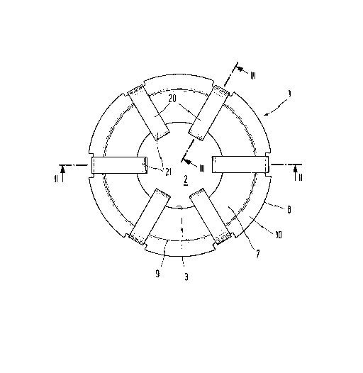
Figure 1 shows a ~op view of an embodiment of the
invention,
Figure 2 shows a section along line 2-2 in Figure 1; and
Figure 3 shows a partial section along line 3-3 in
Figure 1 in a larger scale;
Figure 4 shows a sectional view of permanently excited
commutator motor with clamping plate installed according to the
invention; and
Figure 5 shows an enlaryed view of the motor of Figure
D,,
A clamping plate 1 has an lnner, round plug-in hole 2
with a free inside edge 3~ The plate is provided to hold cup-type
friction beariny not shown. The clamping plate 1 is pushed into

~2~
20365-~865
the seating hole against t.he cup-type bearing in plug-:in direction
6.
The transition zone 7 between the plug-in hole 2 and the
free outer edge ~ of the clamping plate 1 is slightly convex and
has an annular bead 9 followed in raclially outward direction by a
clamping edge 10 so that oil expelled centrifugally radially
outward from the bearin~ during operation can be lntercepted in
the area of the transition zone 7.
Evenly distribu~ed over the circumference of the
clamping plate in the embodiment example are six spring tabs 20
which project radially inward. The tabs have the same width and
thickness and are terminated in angled ends 21 oriented towards
the plug-in hole 2. In the normal position of the clampiny plate
1, the diameter of the circle formed by the offset ends 21 is only
slightly smaller than the diameter of the plug-in hole 2.
The spring tabs 20 are an integral part of the clamping
plate 1. Coming from the transition zone 7, the spring tabs 20
are bent by approximately 180 degrees at t.he bending point 22,
contact the bead 9 and then continue in approximately radial
direction towards the centre of the plug-in hole 2, as is evident
in particular from Figure 3.
As already mentioned ahove, the clamping plate is one
integral part; i~ is stamped out of sheet metal, e.g., spring
steel; the spriny tabs are bent into the position shown by about
180 degrees.
Figure 4 shows a permanently excited commutator motor
having two clamping plates 1, 1 for bearings L, L. Arranged on

2036S-28~5
the inner surface of a .stator housiny S are permallent shell
magnets Ml, M2 for excitation. Fastened at the sides O:e the
stator housing S is a respective support shielcl LS. Each suppor-t
shield LS houses a bearing L supported by a corresponding clamping
plate for 1. A rotor shaft RW is pivotably supported by the
bearlngs L and holds a laminated rotor R and a commutator K. On
the righ~-hand side of the rotor shaft RW between the bearing L
and the commutator K there is a sleeve AS. Similarly on the left-
hand side of the rotor shaft RW there is sleeve DS. These sleeves
are provided for setting the axial play between the shaft and the
housiny.
As can be seen more particularly on Figure 5, the
clamping plate 1 which is described in more detail in Figures 1-3,
is arranged for supporting the bearing L in the shields LS and for
returning the leaking oil slung away by a centrifugal ac~ion of
disk SR of the sleeve AS. The clampiny plate is fixed in its
final insertion position by its outer clamping rim 10 disposed in
a receiving tubular section of the bearing shield LS extending
substantially in the axial direction as shown.
.. ~ '
. .

Representative Drawing
A single figure which represents the drawing illustrating the invention.
Administrative Status

2024-08-01:As part of the Next Generation Patents (NGP) transition, the Canadian Patents Database (CPD) now contains a more detailed Event History, which replicates the Event Log of our new back-office solution.

Please note that "Inactive:" events refers to events no longer in use in our new back-office solution.

For a clearer understanding of the status of the application/patent presented on this page, the site Disclaimer , as well as the definitions for Patent , Event History , Maintenance Fee  and Payment History  should be consulted.

Event History

Description Date
Inactive: IPC from MCD 2006-03-11
Time Limit for Reversal Expired 1998-07-30
Letter Sent 1997-07-30
Grant by Issuance 1991-07-30

Abandonment History

There is no abandonment history.

Owners on Record

Note: Records showing the ownership history in alphabetical order.

Current Owners on Record
ING. LANG & MENKE GMBH
SIEMENS AKTIENGESELLSCHAFT
Past Owners on Record
FERDINAND HOFFMANN
MICHAEL RUB
PETER ADAM
Past Owners that do not appear in the "Owners on Record" listing will appear in other documentation within the application.
Documents

To view selected files, please enter reCAPTCHA code :


To view images, click a link in the Document Description column. To download the documents, select one or more checkboxes in the first column and then click the "Download Selected in PDF format (Zip Archive)" or the "Download Selected as Single PDF" button.

List of published and non-published patent-specific documents on the CPD .

If you have any difficulty accessing content, you can call the Client Service Centre at 1-866-997-1936 or send them an e-mail at CIPO Client Service Centre.


Document
Description 
Date
(yyyy-mm-dd) 
Number of pages   Size of Image (KB) 
Cover Page 1993-10-21 1 17
Abstract 1993-10-21 1 17
Claims 1993-10-21 2 36
Drawings 1993-10-21 2 65
Descriptions 1993-10-21 4 126
Representative drawing 2001-07-18 1 13
Maintenance Fee Notice 1997-09-30 1 179
Fees 1996-06-20 1 76
Fees 1995-06-20 1 68
Fees 1994-06-17 1 58
Fees 1993-06-15 1 45