Language selection

Search

Patent 1287338 Summary

Third-party information liability

Some of the information on this Web page has been provided by external sources. The Government of Canada is not responsible for the accuracy, reliability or currency of the information supplied by external sources. Users wishing to rely upon this information should consult directly with the source of the information. Content provided by external sources is not subject to official languages, privacy and accessibility requirements.

Claims and Abstract availability

Any discrepancies in the text and image of the Claims and Abstract are due to differing posting times. Text of the Claims and Abstract are posted:

  • At the time the application is open to public inspection;
  • At the time of issue of the patent (grant).
(12) Patent: (11) CA 1287338
(21) Application Number: 1287338
(54) English Title: REMOVABLE SHIPPING RESTRAINT SYSTEM FOR APPLIANCES
(54) French Title: SYSTEME AMOVIBLE POUR LE CALAGE D'APPAREILS MENAGERS AU COURS DE LEUR TRANSPORT
Status: Term Expired - Post Grant
Bibliographic Data
(51) International Patent Classification (IPC):
  • B65D 81/02 (2006.01)
  • B65D 85/30 (2006.01)
  • B65D 85/68 (2006.01)
(72) Inventors :
  • ORY, WILLIAM FREDERICK (United States of America)
  • STAUN, PAUL RICHARD (United States of America)
  • WEIR, ROBERT MILO (United States of America)
(73) Owners :
  • WHIRLPOOL CORPORATION
(71) Applicants :
  • WHIRLPOOL CORPORATION (United States of America)
(74) Agent: KIRBY EADES GALE BAKER
(74) Associate agent:
(45) Issued: 1991-08-06
(22) Filed Date: 1986-01-23
Availability of licence: N/A
Dedicated to the Public: N/A
(25) Language of filing: English

Patent Cooperation Treaty (PCT): No

(30) Application Priority Data:
Application No. Country/Territory Date
698,541 (United States of America) 1985-02-05

Abstracts

English Abstract


ABSTRACT
A shipping restraint system for an appliance having
moveable suspension components is provided which includes a
plurality of locking pins engagable in apertures in the
components to prevent their movement during shipping. The
locking pins are held in place by cotter pins which are
attached to a cord directed to the exterior of the appliance.
Removal of the cotter pins will cause the locking pins to
fall under gravity bias from the apertures into receiving
cups thereby unlocking the movable components.


Claims

Note: Claims are shown in the official language in which they were submitted.


Claims:
1. A shipping restraint system for an appliance having a
cabinet with vertical sidewalls, a horizontal bottom wall for
resting on a floor and a plurality of suspension components
including overlying plate members which are movable relative
to one another within said cabinet, comprising:
restraining means for interlocking said components in a
fixed relationship; and,
means for selectively releasing said restraining means
from the exterior of said cabinet comprising a cable connected
to said restraining means for selectively disengaging said
restraining means from said components;
said cable including a free end which extends outward
through an aperture in said cabinet.
2. The shipping restraint system of claim 1 wherein said
restraining means comprises one or more locking pins
engageable with said components and being connected to said
cable extending to the exterior of said cabinet such that
exertion of a force on said cable will result in disengagement
of said pins from said components.
3. A shipping restraint system for an appliance having a
plurality of overlying plate components interior of a cabinet
which are movable relative to one another and arranged in a
generally parallel adjacent manner, comprising:
means defining a coaxial aperture in each of said
components;
a locking member extendable through each of said
apertures in said components;

retaining means to hold said locking member in said
apertures; and,
means for selectively effecting the withdrawal of said
locking member from said apertures comprising a strap member
connected to each of said retaining means for selectively
disengaging said retaining means from said locking pins
thereby effecting the release of said locking members;
said strap member including a free end which extends
outward through an aperture in said cabinet.
4. A shipping restraint system for an appliance having a
plurality of suspension components interior of a cabinet
comprising a base plate, a skate plate and a stabilizer plate
which are movable relative to one another and arranged in an
overlying manner, comprising:
at least one set of vertically aligned apertures in said
components;
a locking pin extendable through said set of aligned
apertures in said components;
retaining means to hold said pin in said apertures; and,
means for selectively effecting the release of said pin
comprising a strap member connected to each of said retaining
means for selectively disengaging said retaining means from
said locking pins thereby effecting the release of said
locking pins;
said strap member including a free end which extends
outward through an aperture in said cabinet;
whereby said pin will fall under gravity bias from said
apertures to release the restraint on said components.

5. The shipping restraint system of claim 4 wherein said
retaining means comprises a retaining pin engageable with said
locking pin above at least one of said components to prevent
said locking pin from falling through said apertures.
6. The shipping restraint system of claim 5 wherein said
release means comprises a strap connected to said retaining
pin to effect removal of said pin.
7. The shipping restraint system of claim 5 wherein said
locking pin is insertable from below said components and has
an enlarged head positionable below said components whereby
said components will be restrained vertically by said head and
said retaining pin as well as horizontally by said locking
pin.
8. In an automatic washer having a vertical agitator
concentrically mounted in a wash tub above a drive assembly
and a plurality of relatively movable suspension system
components interposed between said tub and said drive assembly
all within a cabinet, a shipping restraint system comprising a
means for interlocking against movement said relatively
movable suspension components and means for disengaging said
interlocking means comprising a strap member connected to said
interlocking means, said strap member having a free end
extending outward through an aperture in said cabinet.
9. The shipping restraint system of Claim 8 wherein said
interlocking means comprises at least one locking pin
removably retained in an aligned set of apertures in said
suspension components.
10. The shipping restraint system of Claim 9 wherein a
11

removable retaining pin is used to hold said locking pin in
said apertures.
ll. The shipping restraint system of claim 10 including
a strap connected to said retaining pin to facilitate its
removal.
12. The shipping restraint system of claim 10 wherein
said locking pin falls out of said apertures under gravity
bias upon removal of said retaining pin.
13. A shipping restraint system for an automatic washer
having a vertical agitator concentrically mounted in a wash
tub above a drive assembly and a suspension system including
a fixed plate member and one or more movable plate members
interposed between said tub and said drive assembly,
comprising:
a plurality of vertically aligned apertures in said
members;
a locking pin extendable through each plurality of
aligned apertures;
a retaining pin engageable with each locking pin to hold
said locking pins in said apertures; and,
a strap member connected to each of said retaining pins
for selectively disengaging said retaining pins from said
locking pins thereby effecting the release of said locking
pins;
whereby said locking pins will fall. under gravity bias
from said apertures to release the restraint on said members.
14. The shipping restraint system of claim 13 wherein
said locking pins are insertable into said apertures from
12

below said members and have an enlarged head engageable below
a bottom one of said members and said retaining pin engages
each locking pin just above a top one of said members, whereby
said members are restrained vertically and horizontally.
15. A shipping restraint system for an automatic washer
having a vertical agitator concentrically mounted in a wash
tub above a drive assembly and a suspension system including
a fixed plate member and one or more movable plate members
interposed between said tub and said drive assembly,
comprising:
a plurality of vertically aligned apertures in said
members;
a locking pin extendable through each plurality of
aligned apertures;
a retaining pin engageable with each locking pin to hold
said locking pins in said apertures;
a strap member connected to each of said retaining pins
for selectively disengaging said retaining pins from said
locking pins thereby effecting the release of said locking
pins; and
a cup secured below each of said locking pins to receive
and hold said locking pins when said pins fall from said
apertures;
whereby said locking pins will fall under gravity bias
from said apertures to release the restraint on said members.
16. A shipping restraint system for an automatic washer
having a vertical agitator concentrically mounted in a wash
tub above a drive assembly and a suspension system including a
13

fixed plate member and one or more movable plate members
interposed between said tub and said drive assembly all within
an outer cabinet, comprising:
a plurality of vertically aligned apertures in said
members;
a locking pin extendable through each of said aligned
apertures;
a retaining pin engageable with each locking pin to hold
said locking pins in said apertures;
a strap member connected to each of said retaining pins
for selectively disengaging said retaining pins from said
locking pins thereby effecting the release of said locking
pins;
said strap member including a free end which extends
outward through an aperture in said cabinet;
whereby said locking pins will fall under gravity bias
from said apertures to release the restraint on said members.
14

Description

Note: Descriptions are shown in the official language in which they were submitted.


~733~
"REMOVABLE S~IPPING RESTRAINT SYSTEM FOR APPLIANCES"
_ _ _ _
BACKGROUND OF THE INVENTION
.
Field of the Invention
The present invention relates to a shipping restraint
system for appliances and, more particularly, to a removable
pin locking system for restraining movement of movable por
tions of an appliance during shippiny.
Descri~tion of the Prior_Art
In appliances having movable portions, such as a basket
and tub assembly of an automatic washer, it is necessary to
restrain the movable portions against vertical and horizontal
movement during shipping. If sufficient shipping restraints
are not employed, it is possible for the various portions to
move relative to one another beyond their intended limits
thus causing damage to the appliance. Speci~ically, in an
automatic washer it is possible for the tub assembly to be
shifted laterally against the cabinet, resulting in permanent
deformation of the cabinet or damage to the tub assembly,
particularly if portiQns of the assembly are fabricated of a
plastic material.
Several different types of shipping restraint systems
are proposed in the prior art. U.S. Patent No. 3,249,215
discloses a ring-like structure for use in restraining move-
ment of a washing machine tuh and agitator in which the ring
member serves as a brace between the top cabinet opening and
the top of the tub and also against the agitator, to prevent
movement therebetween. Other patents disclose packing
devices or wedges to restrain movement of the agitator or
basket within the washing machine cabinet. Such patents
include U.S. Patent Nos. 3,335,849; 3,620,365; 3,861,525 and
--1--

:L28733~
4,366,902. In addition to a packing block, U.S. Patent No.
4,366,902 additionally discloses the use of removable braces
to secure a bottom end of the drive assembly to the frame of
the washer.
Although some of the prior shipping restraint devices
may be effective to prevent movement oE various parts during
shipping, they are generally relatively expensive because of
a multiplicity of parts or are cumbersome to install and
remove.
SU~IMARY OF THE INVENTION
The present invention is directed to a very simple and
inexpensive restraint system which locks the movable portions
of an automatic washer suspension system against horizontal
and vertical movement, thereby eliminating the need for
separate upper and lower restraint means such as disclosed in
the U.S. Patent No. 4,366,902. The present invention is
particularly useful in an appliance in which the suspension
system is comprised of three overlying elements or plates
which are movable relative to each other and wherein one of
the elements is fixed or rigid with respect to the appliance
cabinet. A particularly advantageous embodiment o~ the
invention is to utilize a plurality of vertically disposed
locking pins which extend through cooperating apertures in
the three suspension plates to interlock those members against
vertical and horizontal movement. Cotter pins are provided
for retaining the locking pins in place and a strap for
effecting removal of the locking pins connects to each cotter
pin and extends out through an aperture in the back of the
cabinet. Pulling outwardly on the strap causes all of the
cotter pins to be pulled from the locking pins, allowing the
-2-

33~3
locking pins to drop into small plastic receiving cups dis-
posed immediately below each locking pin. These cups are
provided to prevent the pins from rolling around loosely
within the washer and provide means for retrieving the pins
if the suspension is to be again restrained for further
shipment.
Thus, the present invention provides a shipping
restraint which is inexpensive and very easy to assemble and
remove, which operates by interlocking cooperating hori-
zontally slidable suspension members in an automatic washer.
This is done through the use of a vertically extending lock-
ing pin which is gravity biased to fall from its locking
position upon release of retaining means, to thereby unlock
cooperating movable members of the washer suspension system.
Therefore, the washer suspension system is restrained by
interlocking the middle portion of the suspension system
rather than interlocking either or both of the top and bottom
portions of the washer tub and drive assembly. Another
advantageous feature of the invention is that the shipping
restraint system can be released quickly and easily exter-
nally of the cabinet by pulling on the release cord thereby
obviating the necessity of opening various portions of the
cabinet.
BRIEF DESCRIPTION OF T~IE DR~WINGS
Figure 1 is a perspective view of an automatic washer
embodying the principles o~ the present invention.
Figure 2 is a plan view of the suspension system for the
washer shown in Figure 1.
Figure 3 is a partial rear view of the washer shown in
Figure 1.
~3-

~B~338
Figure 4 is a partial sectional view taken generally
along the line IV-IV of Figure 3.
E`igure 5 is a side sectional view showing the restrain-
ing pin in place.
Figure 6 is a top view showing the pin in place, taken
generally along the line VI-VI of Figure 5.
Figure 7 is a perspective view of the retracting strap.
DESCRIPTION OF THE PREFERRED EMBODIMENTS
In Figure 1 there is shown an automatic washer 10 which
operates through a pre-programmed series of washing, rinsing
and drying steps. The washer 10 is enclosed in an outer
cabinet 12 which is attached at its base to a cabinet frame
13. The washer includes a wash tub 14, a perforate wash
basket 16, and a vertical agitator 18 mounted concentrically
within the wash basket 16. An electric motor 20 operates
through a transmission 22 to drive the agitator and wash
basket. The wash tub and drive assembly are mounted on a
suspension system including legs 24. Each of the legs 24 is
rigidly mounted at its lower end to a cabinet frame 13 and at
its upper end to a base plate 26, as is described in detail
in U.S. Patent 4,174,622 assigned to Whirlpool Corporation,
the assignee of the present invention. The base plate 26 is
thus fixed with respect to the cabinet frame 13.
91idingly resting on the base plate 26 is a skate plate
28 which supports a stabilizer plate 30 carrying the tub. As
shown in Figure 2, the three plates 26, 28 and 30 are arranged
in an overlying manner and movement of the tub relative to
the cabinet results in movement of these plates relative to
one another. To prevent such movement during shipping, three
brackets 32 are welded onto the stabilizing plate 30 to

3~2~733~3
overlie both the skate plate 28 and the base plate 26.
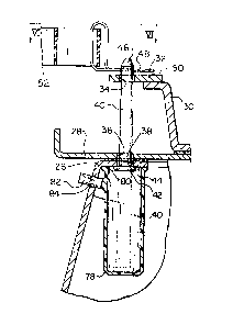
As shown in Figure 5, an aperture 34 is provided in the
bracket 32, a second aligned aperture 36 is provided in the
skate plate 28 and a third aligned aperture 38 is provided in
the base plate 26. Although the three plates are movable
relative to one another the apertures 34, 36 and 38 can be
aligned to permit the insertion of a locking pin 40 up
through the apertures. The pin 40 has an enlarged head 42
which abuts against a bottom surface 44 of the base plate 26
and near a top end 46 there is a through passage for receiv-
ing one leg of a cotter pin 48. The cotter pin placement is
above a top surface 50 of the bracket 32 on the plate 30.
Thus, the pin 40 is captured in the three plates and holds
them stationary relative to each other both vertically and
hori~ontally. As seen in Figure 2, there are three sets of
such pins and apertures thereby providing a ver~- secure ana
stable restraint against relative movement of the three
plates.
In order to effect removal of the shipping restraint
system after the washer 10 has been installed at its final
destination, a removal strap 52, or suitable cord or cable,
is provided. The cord 52 is attached to each of the cotter
pins 48 and extends through an opening 54 in a rear panel 56
of the washer 10. As shown in Figure 7, the strap 52 is
formed in a Y shape with a base leg 58 and two arms 60, 62.
The first arm 60 has one cotter pin 48 attached at an end 64
thereof and a second cotter pin 48 attached at a point 66
between the end 64 and a junction 68 of the two arms 60, 62.
The second arm 62 has the cotter pin 48 attached at a free
end 70 thereof. At the junction point 68, there is a loop 72

l3733~
formed in the strap~
To install the shipping restraint system, the locking
pins 40 are inserted through the apertures 34, 36 and 38, the
cotter pins 48 are inserted into the locking pins and the
strap 52 is directed toward the rear panel 56 of the washer.
The free leg end 58 of the strap is passed through the open-
ing 54 to be exposed on the exterior of the washer chbinet.
To prevent the assembly person from accidentally pulling
one or more of the cotter pins 48 out of the restraining pins
40, there is provided a slitted plug 74 which fits into the
opening 54 in the rear panel 56 and is held there. When the
assembly person pulls the free leg 58 of strap 52 through the
plug 74, the loop 72 will engage the plug 74 and offer a
detectable resistance. At this point, the installer will
realize that the cord 52 is pulled a sufficient distance
through the plug and will stop pulling. To prevent the cord
52 from falling back into the interior of the cabient, the
leg end 58 is formed as an open loop and a power cord and
~ plug 76 for the machine can be passed through the open loop
; 20 thus capturing the leg end 58 on the outside of the machine
cabinet. An additional advantage of using the power cord 76
to retain the strap 52 is that the user at the ultimate
location will be required to pull on the power cord 76 in
order to energize the machine and will thus be alerted to the
strap 52 and will be positively reminded to pull the strap
out of the cabinet.
As the strap 52 is pulled out of the cabinet, the cotter
pins 48 are pulled out of the locking pins 40 and the pins 40
then fall downwardly under the influence of gravity to dis-
engage from the apertures in the plates. To prevent the pins
--6--

~L~8733~3
40 from falling into the bottom of the cabinet and rolling
around or from becoming engaged in other portions of the
mechanism, there is provided below each pin 40 a cup 78 which
has an open top end 80 to abut against the bottom surface 44
of the base plate 26. A tab 82 projects outwardly from the
side of the cup 78 and extends through and is captured in an
aperture 84 in the base plate 26. The cup 78 is thus remov-
ably retained adjacent to the base plate 26 and will hold the
pin 40 after it has been released. IE there is ever a need
to reship the washer and to provide a shipping restraint, the
pins 40 will be available for reuse. The tab 82 can be
disengaged from the base plate 26 to provided access to the
pins 40 and then the cup 78 can be reattached to the hase
plate 26 for reuse.
Thus, there is disclosed a removable shipping restraint
system which interlocks cooperating horizontally slidable
suspension members in an automatic washer. The vertically
extending locking pin 40 is gravity biased to fall from its
locking position upon release of the restraining means, to
thereby unlock the movable members o~ the washer suspension
system. In this manner, the "middle portion" of the washer
suspension system is interlocked rather than interlocking
either,or both of the top and bottom portions of the washer
tub and drive assembly. The restraint system has an
externally operable release means and does not require open-
ing portions of the cabinet or tilting the cabinet to ob~ain
access to the release means.
As is apparent from the foregoing specification, the
invention is susceptible of being embodied with various
alterations and modifications which may differ particularly
--7--

~2~33~
from those that have been described in the preceding specifi-
cation and descri.ption. It should be understood that we wish
to embody within the scope of the patent warranted hereon all
such modifications as reasonably and properly come within the
scope of our contribution -to the art.

Representative Drawing
A single figure which represents the drawing illustrating the invention.
Administrative Status

2024-08-01:As part of the Next Generation Patents (NGP) transition, the Canadian Patents Database (CPD) now contains a more detailed Event History, which replicates the Event Log of our new back-office solution.

Please note that "Inactive:" events refers to events no longer in use in our new back-office solution.

For a clearer understanding of the status of the application/patent presented on this page, the site Disclaimer , as well as the definitions for Patent , Event History , Maintenance Fee  and Payment History  should be consulted.

Event History

Description Date
Inactive: IPC expired 2020-01-01
Inactive: Expired (old Act Patent) latest possible expiry date 2008-08-06
Inactive: IPC from MCD 2006-03-11
Grant by Issuance 1991-08-06

Abandonment History

There is no abandonment history.

Owners on Record

Note: Records showing the ownership history in alphabetical order.

Current Owners on Record
WHIRLPOOL CORPORATION
Past Owners on Record
PAUL RICHARD STAUN
ROBERT MILO WEIR
WILLIAM FREDERICK ORY
Past Owners that do not appear in the "Owners on Record" listing will appear in other documentation within the application.
Documents

To view selected files, please enter reCAPTCHA code :


To view images, click a link in the Document Description column. To download the documents, select one or more checkboxes in the first column and then click the "Download Selected in PDF format (Zip Archive)" or the "Download Selected as Single PDF" button.

List of published and non-published patent-specific documents on the CPD .

If you have any difficulty accessing content, you can call the Client Service Centre at 1-866-997-1936 or send them an e-mail at CIPO Client Service Centre.


Document
Description 
Date
(yyyy-mm-dd) 
Number of pages   Size of Image (KB) 
Abstract 1993-10-20 1 14
Claims 1993-10-20 6 196
Drawings 1993-10-20 2 94
Descriptions 1993-10-20 8 282
Representative drawing 2001-11-15 1 10
Fees 1996-07-17 1 73
Fees 1994-06-09 1 53
Fees 1995-07-09 1 50
Fees 1993-06-28 1 101