Note: Descriptions are shown in the official language in which they were submitted.
~873~g
~ Control devi~e.for a printing.press,
.
The invention relates to a control device for a pri~ting p~ess
with an operator panel with a plurality o~ pushbuttons or
similar actuators.
Such control devices which are used for the remote control of
printing presses are known. In such known control devices a
command can ~e initiated simply by pressing one sing1e button,
as,a result of which there is the possibility of'making a
mistake. The object of the invention is to create a control
device,of ~he initially mentioned type such that the operation
o~ the device is simpl~ified and the possib$1ity of mistake is
reduced. The object of the invention is achieved in that a
~irst group of pushbuttons is provided for selecting a desired
command or machine status,whereby the configuration is such
.~ .
`' : . ~ '
: ' .. ;
.
- 2 - ~
that at least two operations are necessary for having the
command executed or the machine status changed.
_ The advantage of the invention is that the execution of a
command cannot be initiated simply by pressing one single
button of the first group. Ihis reduces the possibility of
error. Since this also dispenses with the possibly complex ~_ _
process of canceling a given command, the operation of the
device is also facilitated.
The required number of operations may differ depending on
requirements; for example, it is possible for a command to
be initiated only when the same command button is pressed
twice. However, thepreferredconfi~uration i~ such that
a separate ~put button is provided for initiating a command
~r a change in machine status.
In an embodiment of the invention in which the control de-
vice exhibits at least one display papel, in particular a
light-emitting diode display panel, there is a second group
of pushbuttons for selecting at ~east:one item of informa-
; tion which is to be displayed on the display panel. Thus,
in an offset printing press with a plurality of servo-
cylinders for each printing unit for setting the ink film
thickness profile it is possible for the actual status of
the settings of the individual servo-cylinders to be repre-
sented on an ink zone display panel, or, instead, the setpoint
status for a specific printing job can be shown, and ink
ductor values (ink stripe length in circumferential direction
of ink ductor roller) and register values can be indicated on
a preerably numerical display panel. The pushbuttons of
the second group are designed to enable the printer before
and particularly while initiating a command by pressing a
pushbutton of the first group to call u~ the relevant infor-
mation on the display panel in order to check whether before
the command is executed it is necessary to make any changes,
'
73~39
for example, in the position of the servo-cylinders~
In an embodiment of the invention the pushbuttons of the
second group are each provided with a visually switchable
indicator. In particular, the configuration may be such
that when a pushbutton of the first group is actuated visual
indicators of the second group which are permanent~y assigned ~ ~-
to said actuatable pushbutton are actuated. The permanerlt
assignment of the visual indicators, particularly LED's,
is such that for all the individual commands or machine
statuses which can be initiated by actuating a pushbutton of
the first group the printer's attention is drawn to the push-
button(s) of the second group whose information he should
know before executing the initiated command in order, on
the basis of his expert knowledge, to judge whether he wants
to make any changes before the final execution of the command.
This simplifies the operation of the device for the printer
since these L~D displays or other visual indicators dxaw his
attention to the information which is<of relevance in each
particular case. It is practical for the configuration to
be such that ~uttons of the second group can also be actuated
without pressing a command initiation button. It is also
possible that after a button of the first group has been
pressed only one single button of the second group is visually
identified. In this case, it may be practical for the display
belonging to thi button to appear automatically on the dis-
play panel~ If other displays are also practical, it is pos-
si~le for these other displays likewise to be made visible,
also without the corresponding button of the second group
previously having been visually identified. It may be prac-
tical for the initiation of certain commands to make at least
one of the buttons of the second group ineffective.
In an embodiment of the invention intended for a printing
press with at least o~e printing unit there is a third group
~lZ~731~9
.~ .
o~ pushhuttons for making a command effective or ineffective
for one or more printing units. In the specimen embodiment
described later, although most commands are generally to be
executed in the same manner for all printing units, there may
6till be cases where the printer, on the basis of his exper-
ience, also wishes to make the aforementioned commands effec-
tive only for some of the printing units. For the later-des-
cribed "position" command, i,e. setting the ink film thickness
profile and the ink ductor values, conversely, it will generallv
be practical to execute the command separately for each
individual printing unit. The configuration may be such that
the command applies to all printing units unless specific
printing units are specified. This group of pushbuttons may
also be practical for printing presses with only one print-
ing unit.
In an embodiment of the invention there is a fourth group of
pushbuttons which are assigned to the printing colours being
; used and which can be assigned to the~pushbuttons of the
third group. In general, although in an ~ffset printing
press with a set number of print~ng units, for exam~le two
printing units, the first printing unit will fre~uentl~ appl~
the colour black, and the second printing unit the other
colour, it may be practical in individual cases to abandon
such a rigid system, and the above-depicted embodiment of
the invention allows the printer to assign the printing
colours to the individual printing units as he desires.
Although internally the device described in the specimen
embodiment works such that, in the final analysis, only the
indivldual printing units are controlled, for example theix
servo-c~linders for the ink film thickness profile, the
depicted assignment of buttons of the fourth group which are
in this case also identified as colour buttons makes it clear
~or the printer which colour belongs to which prlntiny unit,
and embodiments of the invention may also enable the printer,
for example when setting the ink film thickness profile and
the ink ductor values ("position" command) to execute this
`:
~2~3~9
,_ :
. . ~
-- command for a 6pecific printing unit, for example printing ~_
unit No. one~ by pressing the colour button assigned to this
printing unit.
,._
Apart from facilitating machine operation, the depicted colour
assig~ment is also of importance when the control device is
supplied with presetting values for the var:Lous ink film
thickness profiles and ink ductor values by means of data
transmission methods. In such a case the depicted colour
assignment ensures that these supplied data cause the servo-
cylinders to be adjusted only on those printing units which
are assigned to the respective printing colour.
- ` In an embodiment of the invention the pushbuttons of the fourth
group, lOe. the colour buttons, are each provided with a visual
indicator, and the configuration is such that when a pushbutton
of the first group is actuated visual inaicators ~f the fourth
group permanently assigned to said pushbutton are actuated.
This embodiment may be practical for commandS in which a
limitation of the command to a specific printing colour or
equally to a specific printing u~it i-~ practical. This embodi-
i ment can, therefore, be replaced with the same effect by a
'!`';' different embodiment in which the visual indicators are assigned
not to the printing colours, but to the printing units.
The last-described embodiment of the invention can be further
developed such that a further visual indicator "all colours"
or~ compietely equivalent, an indicator "all printing units"
is provi~ed. In the later described specimen embodiment the
confl~uration is ~uch that the last-mentioned indicator "all
colours" or "all printing units" is not àssigned any particular
pushbutton, but this indicakor is incorporated in the execution
o~ the command if the printer does not limit the execution o~
;; the command to a ~pecifia colour or a specific printing unit.
.,
.
~2~373~3~
_ - 6 _
In an embodiment of the in~e~tion in which the printer can
select information for presentation on the display panel, the
configuration is such that the values of the currentl~ dis-
~J pla~ed information can be changed and the changed values o~ly
become e~ecti~Je ~or 'che co~trol æ~e~ice i~ co~ar~d executionis initiated. The advantage of this is that, for example,
the printer can change an ink film thickness profile as he
thinks fit on the display panel, but he still has the possi-
bility at all times of preventing the final setting of the
thus changed ink film thickness profile. This embodiment is
particularly important when information stored in the de~ice
is overwritten, i.e. destroyed, by the definitive loading of
the changed values.
In an embodiment ~f the invention a ~arning indicator is pro-
vided for at least one of the buttons of the first grouD,
said warning indicator becoming effective when the afore-
mentioned button is actuated. The advantage of this embodi-
ment is that the printer's attention càn be drawn to the
fact that, prior to the execution of the command initiated
by him, it would be practical be~orehand to execute one or
more commands, particularly in order to prevent a loss of
information. In an embodiment of the invention the warning
indicator may exhibit a device for actuating a visual indi-
cator which is assigned to at lcast one of the remaining
buttons of the first group. In a further deve-lopment of
this idea, the configuration may be such that the aforemen-
tioned remaining buttons of the first group are visually
ident~ied, particularly by an LED indicator, only when the
printer presses a special button. In this last-mentioned
case the warning indicator thus only makes the printer generally
aware of the ifact that there are one or more commands which
should be possibly be executed prior to the execution of the
initiated command, and if the printer is not sure whether he
has already initiated these commands or what commands these
~2~73~9
are, he c~n press the aforementioned button and see a visual
display of these commands which may have to be execu~ed
beforehand.
In embodiments of the invention it may be practical after
the actuation of a button of the first group to render those
buttons of the operator panel ineffective whose actuation is
not advisable or might even lead to malfunctions. Usually,
these are at least the other buttons of the first group.
In an embodiment of the invention which can also be realized
independently of the initially described invention, there is
a button for initiating a format shift command. This command
is particularly useful when Printing jobs originally inten~ed
for a smaller, i.e. narrower, printing press are to be car-
ried out on a wider press. This command is also useful when
a job intended for a narrow press is carried out on a wide
press, twice on the same sheet side by side.
<
Further features of the invention relate to the different
com~ands which are assigned to t4e pushbuttons of the first
group and which are listed in the description and in the
claims.
It is practical to provide a cancel button in order to be
able to abort a command which has not yet been initiated for
execution or a command which, although ~eing executed, is not
yet completed.
In so far as reference is made above and in the ollowing des-
cription to pushbuttons, it is pointed out expressly that
pushbuttons are merely viewed as a very advantageous type of
ac~uator by which the printer can communicate his instructions
to the control device. However, all other devices suitable
for the communication of instructions also fall within the
scope of the invention, such as sensors, touch-buttons, rotary
.
,
.
. .
~738~
_ 8 -
-
switches, rocker switches and actuation by light pen. It is
considered especially important for the ease of operation by
the printer that the individual controls, such as pushbuttons
or similar, have their fixed position on the operator panel,
f i.e. the printer need not enter his instructions via a type-
writer keyboard, while possibly also taking account o in-
structions which appear on a screen; although these last-
depicted possibilities are not considered as advantageous as
the fixed layout of the individual pushbuttons on an operator
panel, these possibilities should not be excluded from the
protection of the invention-
Further features and advantages o the invention result fromthe ~ollowing description of a specimen embodiment of the
invention with reference to the drawing, which shows essential
details of the invention, and from the claims. The individual
features may be realized individually or in any desired com-
bination in an embodiment of the invention.
~. ~
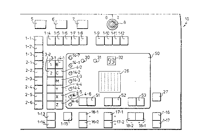
Fig. 1 shows the main part of the operator panel of a control
device for a printing press. -:
Fig. 2 shows a display panel of the operator panel with further
control buttons.
The operator panel 10 shown in Fig. 1 exhibits a first group
of pushbuttons which are identified by the reference symbols
1-1 to 1-17. These pushbuttons are command initiation buttons,
i.e. buttons for initiating a command and in one case also for
initiating a machine status of the control device.
Furthermore, the operator panel 10 exhibits a second group of
pushbuttons which are identified by the reference symbols
2-1 to 2-6 and which are used for selecting an item of infor-
mation which is to be displayed on a display panel 20 in Fig. 2
.
11 z~738~
and 50 in Fig. 1. A third group of pushbuttons exhibits, in
the example, merely the two pushbuttons 3-1 and 3-2 which are
identified by the numbers 1 and 2 and/ assuming that the
control device is intended for a printing press with only
two printing units, are assigned to these two printing units.
Underneath the buttons 3-1 and 3-2 there are four empty places
in the operator panel 10 which can be provided with buttons
corresponding to the number of printing units if the control
device is intended for use with a printing press with a
maximum of 6 printing units.
A fourth group of pushbuttons identified by the reference
symbols 4-1 to 4-6 are used for assigning colours to the
printing units and are referred to in the following as colour
buttons for short. From top to bottom these colour buttons
are assigned to the colours black, cyan, magenta, yell~w,
there also being two additional colours identified by the
letters X and Z. If two identical colours, e.g. black, are
used in the printing press, then it is~practical to use
button X (~-5) for the backing-up unit and button B (4-1~
or the recto unit so that it is~clea~ which colour belongs
to which printing unit. ~ith the machine, for example, the
colouxs black and cyan can be printed in a first run, and
magenta and yellow in a second run for one and the same
printing job.
In its uFper part the operator panel 1~ a~so exhibi~s an in-
put button 5 with which a command input is completed and the
execution of the command is initiated. It also exhibits a
warning indicator button 6 and a cancel button 7 with which
a command which has not yet been fully entered can be canceled
and a command which is in the process of being executed but is
not yet fully completed can be aborted. Furthermore, there
~s a key-operated switch 8 which makes it possible either to
switch off the entire device, to switch it on or, in position
`
G- .
.
~7~8~1 .
"2" merely to activate the displays of the device whereby,
however, no commands or control signals can be entered
through the device.
Closely juxtaposed to each of the individual colour buttons
is a light-emitting diode 14-1 to 14-6; there is also a light-
emitting diode 14-7 which jointly indicates "all colours".
In the lower part of the operator panel there are command
initiation buttons 1-13 and 1-14 for switching on a light
pen; there are also control buttons 16-1 and 16-2 and a
command initiation button 1-15. When button 1-15 is acutated
the control buttons 16-1 and 1~-2 are used for the joint ~er-
centage adjustment of the ink film thickness profile; other-
wise for adjusting the ink ductor va~ue. The value of the
percentage adjustment of the ink film thickness profile or
ink ductor value is indicated on a numerical display 51.
Control buttons 17-1 and 17-2 as well as 18-1 and 18-2 are
used for adjusting the circumferential registers or side
registers of the printing press. The<adjustment for one
single printing unit is performed in conjunction with one of
the pushbuttons 3 or 4. If desired, using command initiation
button 1-17 the shifting operation bv a desired number cf
millimetres entered by buttons 17 and 18 by pressing the
appropriate number of times can be extended to all registers.
By means of a command initiation button 1-17 all or individual
registers can be reset to zero in conjunction with the buttons
3,~ and the lndicators 14-1 to 14-7. The positions and/or
shift values of the respective registers can be indicated by
means of numerical displays 52 and 53 or can be preselected
by means o buttons 17,1~. The position of the circumferen-
tial rçgisters is indicated by a light-emitting diode panel
26 with six columns each of 15 light-emitting diodes. Since
frequently it is only the relative position of the registers
in relation to each other which is of lnterest, by means of
a control button 27 it is possible to reset to zero the dis-
play for the circumferential registers irrespective of their
actual position so that further changes can easily be executed.
.
,. - . . ~ . ~
, . ~ .
.
, ' '
1~73~9
The operator panel 10 also exhibits a light-emitting diode 30
for indicating a stoppage of the printing press in order to
tell the printer that, for example, a register adjust~ent is
not possible during this stoppage. Furthermore, there is a
light-emitting diode 31 which indicates a failure of the
computer 1 contained in the control device.
A numerical display 32 makes it possible in the event of faults
or malfunctions to indicate to the printer the type of fault
or malfunction.
The diode display panel 20 in Fig. i~ contains 32 columns each
of 16 light-emitting diodes which are assigned to the individual
ink zones of the printiny press whereby each ink zone exhibits
a servo-cylinder for adjusting the ink film thic~ness profile.
The ink zones are identified by Z1 to Z32.
There are two control buttons 36-1 and 36-2 below each LED
column of the display panel 20. The light-emitting diode
panel 20 serves not only to indicate the actual position of
the servo-cylinders, but also seEVes other purposes. With
the control buttons 36 the display of the light-emitting diode
panel 20 can be changed for each individual column, and it
is also possible for other, subsequently explained control
operations to be effected.
The individual command initiation buttons 1~1 to 1-17 have
the following significance:
Button 1-1: position command.
With this command the position of the servo-cylinders for the
individual ink zones and the ink ductor values can be changed. r
Button 1-2: correction control command
With this command the printer can make the control device use
,. .
11
- l2-~2~73~g
' '~r . ':
externally supplied data and setting values calculated thexe - ~
from for the servo-cylinders and ink ductors for the once- -
only ad~ustment of the servo-cylinders and ink ductors.
,~
Button 1-3: automatic correction command.
With this command it is possible to initiate the continuous
automatic correction of the servo-cylinders and ink ductors
as a function of data which are suPplied externally, for
example from a measuring device, and which are converted into
servo actuation values in the control device.
Button 1-4: colour assignment.
With this command it is possible for a standard assignment
of colours to printing units stored in the control device
(in the order of the printing units: black, cyan, mage~ta,
yellow, X, Z; Fig. 1) to be changed if necessary. With the
; standard assignment each printing unit is assigned that
colour which is identified by the colour button 4 which is
located in the operator panel immediat~ly to the right of
the corresponding printing unit button. When the colour as-- -
signment command is initiated the prInter can, by simultan-
eously pressing a printing unit button 3 and a colour button
4, preselect the desired alternative assignment and have it
indicated (by lighting up of the pressed button) and can
also have this implemented by input button S.
. ' ,
Button 1-5: ink reduction command.
With this command the ink film thickness can be brought to
the value zero for all ink zones and any desired printing
Ullits, and the ink ductor value can be brought to the maxi-
mum value if it is desired to make the ductor and the follow-
ing inking rollers free of ink as quickly as possible.
Button 1-6: format shift command.
With this command ink film thickness profiles can be shifted
laterally zone by zone. This may be of relevance when
:
- ` ~ . -
` ~2~73~
_ 13-
~ .
changing a job from a smaller press to a larger one because,
in general, it is required that the printed sheets or webs
run through the printing presssymmetrically, i.e. at equal
J~ distances from the ends of the impression cylinders. If,
for example, the presetting values for the individual ink
zones are available on magnetic tape for a smaller press and
these are entered in a larger press, then these entered
values will not correspond to the required symmetrical posi-
tion of the sheet in the press because in a smaller press
having for example 16 ink zones, zones Z1 to Z16 corresPond
to the full machine width whereas zones Z1 to Z16 on a press
with 32 zones correspond to the left-hand half of the machine
so that it is necessary to shift 8 ink zones to the right.
This command can also be used to transfer the above-assumed
narrow format with a width of 16 z~nes to a larger press in
that it is possible to work with double efficiency, i.e. the
image which the small press has only printed once is printed
twice side by side by the larger press~on a wide sheet or on
a wide web.
After the actuation of the command initiation button 1-6
"format shift" this button itself lights up continuously, as
do the light-emitting diode 14-7 "all colours" and button 2-4
"storage indicator", because a shift of format should normally
concern all printing units and thus all colours and the format
shift operation should always take place before positioning,
i.e. before setting the servo-cylinders. With an optional
button 36-1 it is possible to shift the pro~ile zone by zone
from left to right whereby with each press of the button the
profile moves on by one æone or, in the case of continuous
actuation, there is a continuous shift. With an optional
button 36-2 it is possible in a similar manner to shift the
profile zone by zone to the left. The display which is pre-
sent in the LED column of zone Z32 before shifting to the
right appears after one shift step to the right in the LED
:~2~73~3~
lg
colur~ Z1; in the same manner in a display memory connected
to the LED display 20 the data contained there are cyclically
shifted so that no data can be lost when shifting to right
and left. When the correct shift has been performed, the
printer actuates the input button 5, as a result of which
the data so far stored in the display memory are loaded into
a presetting memory of the device (the previous data are over-
written) and are now available for setting the servo-cylinders
whereby this setting operation is initiated by pressing the
button 1-1 ~position).
Button 1-7: format limitation command.
This command is used for setting the ink film thickness to
zero for all zones outside the format being printed and :Eor
all printing units. This is done on a once-only basis and
excludes the ink film thickness in these zones from computation
operationsfor externally supplied data. After the actuation
of button 1-7 which is lit permanently~after being actuated,
any existing format limitation is indicated in that a special
light-emitting diode 40 provided~below each LED colu~n of the
display panel 20 lights up for all format-limited zones, where-
as the light-emitting diodes 40 of the non-limited zones flash.
Other light-emitting diodes of the display panel 20 do not
light up. In the operator panel 10 the light-emitting diode
14-7 "all colours" lights up whereby, in the specimen embodi-
mentl no other LED displays appear. If button 36-1 is now
actuated for a limited zone, the format limitation is canceled
and the corresponding diode 40 flashes. At a oreviously non-limited
zone is limited by actuating the corresponding button 36-2,
and the corresponding light-emitting diode 40 makes the trans-
ition from flashing to being lit continuously. The format is
limited in such a way that when a button 36-2 in the right-
hand half of the display panel is pressed the zone assigned
to this button and all zones to the right of it are limited,
3~3~
_ 15 -
whereas, when a button 36-2 in the left-hand half of the
display panel 20 is pressed, this zone and all zones to the
left of it are limited. The releasing of format-limited
zones by pressing a button 36-1 is performed from the pres-
sed button towards the format centre. Irrespective of the
initia~ed command, the format-limited zones are visible in
the correction display (button 2-2) in the diode row 40.
Button 1-8: zone disable or enable command.
This command makes it possi~le ~y actuating buttons 36 2 or
36-1 to disable or enable certain zones for the correction
control and automatic correction commands. This disable which
is visible in the correction display in the diode row 40 has
no significance for other commandsO In particular, a manual
adjustment is possible during the correction control and auto- r
matic correction commands whereas, during these commands, the
non-disabled zones are not manually adjustable. It is advis-
able for this command to be executed separately for the in-
dividual colours of a printing unit; t~erefore, after the
button 1-8 has been pressed all those light-emitting diodes
of diodes 14-1 to 14-6 flash which correspond to a colour
which is acutally in use. ~he printer is now able, by pres-
sing one of the buttons 4-1 to 4-6 or optionally also by
pressing one of the printing unit buttons 3-1 or 3-2, to
select that colour and thus also that printing unit for
which zones are to be disabled or enabled. With these com-
mand~, only that zone is disabled or enabled whose corres-
ponding pushbutton 36-2 or 36-1 has been pressed.
Buttons 1-9, 1-11 and 1-12 correspond to the commands read
in, record and erase tape and relate to control commands for
a magnetic tape cartridge unit which is installed in the
control device. If the printing press connected to the con-
trol device is to be prepared for performing a new printing
121373~
~ 16 -
,,~
' j.r .
job, then the presetting data for the servo-cylinders and
ink ductor values which are stored on magnetic tape are,
after actuation ~f pushbutton 1-9 read into the display ''
memory which is assigned to the display panels 20 and'50.
On the light-emitting diode panel 20 and display panel 50
the printer can observe the entered values and, for example,
can detect that an incorrect cartridge has been read in by
mistake or that the data are incorrect. In such a case, the
command is aborted by pressing the cancel button 7 with the
result that the read-in data do not influence the working of
the control device. If, on the other hand, the data are to
be definitively loaded into the control device, the com~and
is completed by pressing the input button 5.
Button 1-~0 causes the actual values for the positio~ of the
servo-cylinaers ana in~ ducto~ ~o be stored into the memory
of the control device. When the actual values have bee~
stored in this manner, they have the function of setpoint
values for the position of the servo-cylinders and ink ductors
during the further operation of the control device. The stor-
'age of the actual values into the memory is also necessary ''
if these actual values are subsequently to be stored through
the command 1-11 "record on tape'; since the storage of data
onto magnetic tape takes place from the memory.
The erase tape command is used to prevent old information
remaining on a tape, thus possibly leading to faults in the
setting'up of the press. In addition, the tape is now avail-
able for the storage of other values.
It is indicated below which commands must be initiated for
the warning button 6 to light up, and which of the further
command initiation buttons flash in this case when warning
bu'tton 6 is pressed.
- 17 _ ~2~3~
..q
?~
Button 1-1 ~position cor~mand): -
Button 1~4 flashes (colour assignment command);
Button 1-5 (ink reduction command):
Button 1-10 flashes (storage command);
Button 1-9 (read in command):
Button 1-11 flashes (record command);
Button 1-10 (storage cor~mand) or hutton ~-11 (record command~:
Button 1-10 flashes (storage command);
Button 1-12 (erase tape command):
Button 1-9 flashes (read-in);
Eutton 1-13 or 1-14 ~control buttons for data input into the
diode display panel 2~ by means o light pen), or control but ;~
ton 1-g Iread in command): after the warning ~utton 6 is
pressed the button 1-11 flashes (rec~rd command).
.
The flashing of the above-mentioned buttons draws the atten-
tion of the printer to the possible threat of data loss. I~,
prior to the execution of the pre~ious~y initiated command,
the printer would like to execute a cor~mand ~hich has been
indicated by a flashing button, then he presses the cancel
button 7 and initiates the desired cor~and. When the last-
initiated command has finally been completed by pressing the
input button 5, the originally initiated and, as depicted
above, interrupted command must be initiated anew. The con-
trol device thus does not initiate cor~mands independently,
but all commands must be initiated by the printer. It is
also possib]e to have the configuration such that when the
corNmand `initiation button flashing after the actuation of
the warning button 6 is pressed the command assi~ned to this
button is initiated and the first-initiated cor~and is cancelled
~ithout it being necessary to actuate the cancel button. .-
`` ~2~'73~9
_ 18 -
When a command is initiated by pressing one of the command
buttons 1-1,1-2,1-3,1-5,1-6,1-8 to 1-17 which correspond to
commands which can be suitably executed for individual,
~?
several or all colours/printing units, the button itself
lights up continuously as does the light-emitting diode
14-7; in addition, however, the light-emitting diodes 14-1
to 14-6 assigned to the colour buttons 4 also flash. If a
printing unit button or colour button assigned to one of
these flashing light-emitting diodes is pressed, then the
originally flashing diode lights up continuously and the
light-emitting diode 14-7 goes out. Further desired print-
ing unit buttons or colour buttons can be actuated successively
whereby the corresponding flashing light-emitting diode then
always lights up continuously and thus informs the printer of
the selected printing units/colours. The input ~utton 5 is
then used for executing the command on the actuated printing
units/colours. This selection possibility also exists, as
is shown by the last-mentioned co~mands, for reading in from
magnetic tape, recording and erasing ~he tape; partial erasing
is therefore also possible.
For the format limitation command 1-7 such an extension of
the selection possibility to individual printing units is not
practi~al and, therefore, n~ne of the diodes 14-1 to 14-6
~lashes.
For the ~ormat shift command 1-6, although generally a shift
for all colours is useful, it may still be practical to ~er-
form the shift operation merely for some of the colours.
The buttons 2-1 to 2-6 controlling the display on the light-
emitting diode panel 20 have the following significance: r
Button 2-1: density trend display; button 2-2: correction
display;
., . .. ._ .. .. __ _ _ _ __ _ ~ ., . .... ~
~2B7;3~9
,,~
Button 2-3: difference display; button 2-4: storage display;
Button 2-5: profile display; button 2-6: fine display. By
pressing one of these above-mentioned buttons the correspond-
ing information appears on the displays 20 and S0.
The density trend display sta~es whether the actual ink density
values measured by a sheet measuring device di~fer from the
respective setpoint value, and in ~hich direction and to what
extent.
The correction display shows the externally supplied data and
the values converted into control signals. The correction
display switches on automatically when the commands "correc-
ti~n control" or "automatic correction" are initiated. r
The difference display shows the difference between setpoint
and actual values for the position of the servo-cylinders
and ink ductors values.
The storage display shows the setpoint values for the position
of the servo-cylinders.
The profile display shows the actual position of the individual
servo-cylinders for each individual zone in 16 steps. The
additionally selectable fine display which makes use of the
same light-emitting diodes as the profile display also shows
the exact posit~on o the actual value between two neighboùr-
ing llght-emitting diodes of the ~rofile display whereby, for
the finè display, this distance between the light-emitting
diodes used for the coarse display is extended to 16 light-
emitting diodes. So that the profile display can be distin~uished
from the fine display, the light-emitting diodes used for the
fine display flicker, and they are lit slightly less brightly
than the light-emitting diodes used for the profile display.
' `
~L2~7389
~, - 2~ -
'i.r '''
When the storage display, i.e. the display of the stored
setpoint values, has been switched on by means of the command
buttons 1-13 or 1-14 which represent two slightly different
light pen commands, the printer can, on the light-emitting
diode panel 20, change the displayed profile selected by
button group 3 or 4 either by means of light pen or by means
of buttons 36-1 and 36-2 and, by pressing the input button
5, he can enter the thus changed profile for the selected
colour into the memory of the device as the new setpoint
value. By presslng the button 2-5 for the profile display
and, if necessary, also button 2-6 for the fine display, the
printer can view the actual values for the position of the
serv~-cylinders and ~an change these actual values as he
thinks fit, likewise by means of the light pen or buttons
36-1 and 36-2
;:
If, for one of the above-mentioned light pen commands, all
colours are selected, an artificial profile appears on ~he
light-emitting diode panel 20 in the form of an upward-pointing
very blunt arrow tip which extends over the entire wi~th of
the display panel 20 and whose tip ll-es in the area of the
format centre in zones Z16 and Z17 in order to make the printer
particularly aware of the fact that he has selected all
colours/all printing units. For safety reasons, this dis-
played profile cannot be loaded into the memory without
further ado; on the contrary, command execution is only pos-
sible when the artificial profile has been changed at at
least two zones by the printer.
The ink ductor value appears on the numerical display 51.
This is the value of the ink ductor stroke in percent of the
maximum ductor stroke which is possible on the printing
press. If, in light pen mode, all printing units have been
3L2~373~9
2~ _
selected, there appears on the display 51 a mean value for
the ink ductor value, in the example the nurnber 50. The load- ~
ing of this value into the memory, as a result of which all
~Ir~
ink ductors would be set to this value, is not possible
simply by pressing the input button 5, but command execution
is only possible when the value indicated by the display 51
has been acknowledged or changed. In the example this is
done by buttons 16-1 and 16-2. When button 16 1 is tapped,
the value indicated in the display 51 increases by 1. This
value could now be loaded into the mernory by pressing the
input button 5. ~f, on the other hand, the value 50 is to
be entered, the printer briefly taps button 16-2, thus bring-
ing the indicated value again to 50. He can now enter this
value by pressing the input button 5. The selection of all
colours is visually identified on the dispIay panel 51 by
the flashing of the number shown in this display 51.
Immediately a button of the first group (1-1 to 1-17) is
pressed it i5 lit continuously. Buttons of the operator
panel 10 which after initiation of a corr~and are released
for further actuation or light-e~itting diodes or displays
assigned to the latter flash, after the pressing of the
button the latter or the corresponding light-emitting diode
or display is lit continuously. Ihe input button flashes
after the initiation of a command, is lit after being pressed
and goes out after the execution of the command. At this time
all other LED displays in the executed command also go out,
and the display status prior to initiation of the cor~mand is
automatically selected again, i.e. the display panels show
the information which was visible prior to initiation of the
last command.
The buttons 2-1 to 2-6 are switched on by pressing and are
switched off by renewed pressing or by another button 2. For
~2~73~9
- 2~ -
,~............................... ..
easier identification, the buttons of the first group are
orange, the buttons of the second t.o fourth groups white.
The depicted visual identification of previously actuated
buttons, of buttons which may still re~uire actuation by the
printer, and the depicted visual identification of displays
on the display panels gives rise to a process of operator
guidance; in operating the device, the printer is thus
guided by the device itself. Ihis guidance facilitates the
breaking-in of new personnel, prevents errors and leads to
systematic working,
.. _ . ~ _ .. . _ . _ _ , . _ _ . . . . . _