Note: Descriptions are shown in the official language in which they were submitted.
~.2~75~
MULTI-FREQUENCX JET V13NTILATION TEC~3NIQUE AND APPARATUS
BACRGROUND OF T~E INVENTION
1. Field of the Invention
This invention relates generally to ventilators for
supplying gas to facilitate and support human respiration and
particularly to ventilators which employ a high frequency jet of
gas for respiratory therapy. More specifically, the present
invention is directed to enhancing ventilation at
supraphysiologic rates and especially to maximizing the tidal
lo volume o gas delivered to a patient during respiration therapy
while slmultaneously minimizing patient discomfort and the
possibility of causing or~aggravating trauma. Accordingly, the
general objects of the present invention are to provide novel and
improved methods and apparatus o~ such character.
2. Description of the Prior Art
While not limited thereto in its utllity, the present
invention is particularly well suited to high frequency jet
ventilation. The u e of high frequency jet ventilation has
proven to be~quite beneficial in the treatment of certain
20 respiratory conditions. ~In hi~gh frequency ventilation, rather ~-
than m~oving~gas~in~bulk~quan~tity into the gas exchanging areas of
the~lungs~,~ ventllation is aohieved by enhancing the mass transfer
prooesses`~in the~lungs~ through high~frequenoy oscillation of the
suppl~ied gas.~However,~as the pulsation ~requency of the gas
d~ellve~red~by a ~et~ventilator increases, sup~lying the necessary
tidal~volume~of~ i~nhalation ~as becomes more difficult and is
li`m~ited~by-the~response time~of meohanisms employed for generating ~`
'.''' .' `,,'-.,:, '': ` ' ,' ~ ,'. ', ' ' ' ., ;"''' ' " ` ' " '
121375~4
the gas pulses. In add,ition, the requirements of
reliability, ease of maintenance and susceptibility
~o sterilization are important design considerations
for a ventilator. Portability is a further desirable
characteristic. Accordingly, the principal objec-
tives of the present invention are to provide a new
and improved ventilation technique and a multi-
frequency jet ventilator which operates in accordance
with this technique and is compact, relatively easy
to maintain, capable of being easily sterilized and
supplies a maximized tidal volume of ventilation gas
flow over a wide range of frequencies and duty
cycles.
~ SUMMARY OF THE INVENTION
In accordance with a particular embodiment
of ,the invention there is provided a high frequency
jet ventilator~comprising a module with a breathing
; gas~inlet port and a vent port coaxial therewith in~
~communication across a chamber characterized by a
~ nozzle~for~the introduction of high velocity gas
pulses along the~chamber~to entrain breathing gas
~towards~an ou~tlet for,connection to the mouth of a
`~ patl~en~t.~
~ In accor~dance with a further embodiment of
~ the;invention there is provided a variable frequency
et~ventilator system~comprising~
entrainment module means'for defining an
entralnment chamber~having an axis and a supp ly
outlet~whlch;is coaxial with said chamber, said
30~ entrainment~module~means further defining an
in~iet p~ort and a~constantly open vent port for ~ -
sald entrainmen't chamber, said inlet and vent
por;ts be~lng~ln un~interrup;ted fluid communication
via~sai~d ent~rainment~chamber whereby gas
35~ en~erlng'sald~entralnment chamber through said
Z875'~4
- 2a -
inlet port may continuously 10w through said
vent port, each of said ports haviny an axis and
upstream and downstream ends, said inlet port
and said vent port being generally axially
aligned;
means connected to the upstream end of said
inlet port for continuously supplying humidified
gas to said entrainment chamber via said inlet
: port to thereby establish a bias flow across
lO : said entrainment chamber between said inlet and
vent ports;
: means for generating pulses of gas;
: means for controlling said pulse generating
~means to vary the frequency of generation of the ~
~ : gas pulses; :
: nozzle means for imparting a high velocity
to gas~pulses, said:nozzle means having a
discharge:end which opens into said entrainment
~ ~ .
~ chamber~ said nozzle means being fluldically
20 ~ coupled to said pulse:generating means to
recelve~the~pulses of: gas whereby hlgh velocity : ~.
ga`s~pulses:are~discharged lnto sald entrainment -~
chamber,~ said:nozz:le:means:being oriented:to
ca~u~se the-~discharg:ed gas:p:ulses to be directed
: ~2:5~ along~said~entrainment;chamber axis;toward said
supply~ outlet~,~said~:nozzle:means:being :~ :;
poslt~ioned such~that~hlgh velocity ga~s pulses : -~
dl~scharged:f;rom sald~nozzle means:will entrain
humidi~fied~gas~from the::bias flow to produce
3~0~ ;humldlfied:gas~ pulses which exit said supply . .
outlèt;:~:~and;~
means~couple~d to said entrainment chamber
supply out~let:for`~delivering the~humi:dified gas
p~ulses~to:a~:p~atien:t':s:respiratory system.
2875'1~L
- 2b -
sriefly stated, apparatus ln accordance
with a detailed embodiment of the invention comprises
a ventilator system which includes a novel
entrainment module. The entrainment module forms an
entrainment chamber having an inhalation gas supply
outlet, an inlet port for a bias flow of low pressure
gas and a discharge or vent port. The inlet and
discharge ports are axially spaced from the supply
outlet and are located at generally diametrically
opposite positions of the entrainment chamber. The
low pressure gas, which will customarily be
humidified, is continuously supplied to the inlet
port from a first gas source to establish the bias
flow during operation of the system. A nozzle
~extends into~the entrainment chamber in a direction
which is generally axially aligned with the inhala-
tion gas supply;outlet. The nozzle is in fluid
communication with a source of relatively highly ~ -
~ pressurized gas~pulses and serves to inject a series
of high velocity pressurized gas pulses into the !~
entr~ainment chamber for traversal thereof in a
generally axlal;
~Z~5'~
direction toward the supply outlet. The gas pulses are injected
from a zone generally located between the bias flow inlet and
discharge ports, there being one high pressure pulse injected
during the inspiratory phase of each cycle of the ventilator. A
high velocity pulse from the nozzle entrains a relatively large
amount of the low pressure gas from the bias flow in the
entrainment chamber to produce an inhalation pulse which exits
the chamber supply outlet. During each expiratory phase, between
the injection of successive pulses from the nozzle, gases in the
entrainment chamber, including CO2 exhaled by the patient which
flows into the chamber via the supply outlet, are vented through
the discharge port.
The interior shape of the pulse injection nozzle is either
convergent or convergent-divergent to increase the quantity of
gas from the bias flow which is entrained. The entrainment module
has a substantial1y T-shaped configuration, with the supply
outlet being axially spaced from the nozzle opening and generally
coaxial therewith, and contains no moving parts.
A conduit couples the source of high pressure ventilation
gas to the nozzle. A valve is interposed in this condult to
selectively interrupt the flow of pressurized gas to generate the
high pressure gas pulses. The valve is actuated by a solenoid
which drlves the valve from a closed to a fully open position.
~n electronic control circuit provides signals which control the
operation~of the solenoid. These command signals have a
frequency, pul~se width and duty cycle whlch may be selected to
provide the~optimum ventilation program for the patient to be
trea~ed. The co-nand signals have a generally stepped waveform
: . : . . .
~: " . . . . -, . . . .
. . .
,
s'~
which includes an initial overdrive voltage of predetermined
duration The overdrive voltage functions to reduce the time
intexval for the solenoid to change the state of the valve
whereby the time required for the valve to switch from the fully
closed to fully open condition is minimized.
The novel method of the present invention includes the steps
of creating a humidified bias flow of gas and entraining gas from
that bias flow to create a highly humidified inhalation gas. The
entrainment consists of subjecting the bias ~low to the effect of
lo high velocity pulses of gas derived from a high pressure source
of entrainment gas. The invention further contemplates the
exercise of control over the entrainment gas to vary the
frequency, duration and width of the gas pulses to satisfy the
requirements of the treatment being performed.
BRIEF DESCRIPTION OF T~E DRA~INGS
Figure 1 is a functional block diagram of a multi-frequency
jet ventilator in accordance with the present invention;
Figure 2 is an enlarged f~ragmentary sectional view of a
preferred embodiment of the entrainment module of the multi
frequency jet~venti;lator of~Figure 1;
Figure 3 is~a functional block diagram of the control module
of the multi-frequency jet ventilator of Figure~l;
Figures~4a, 4b and 4c are graphical illustrations of gas
pulse~trains~provided;to~the entrainment module of Figure 2 in
response~to~the control signals generated by the control module
of Figure 3;~and~
Figure~5 is~ a wavefo~rm~diagram of a control voltage
. . :
generated~by~the controI~ module of Figure 3.
~ 4
:~
- : : .: : ; . .. . : ..
. . . ~ :
. . . : . j ., . :.
~Z8~44
DETAILE:D DI~SCRIPTION OF TI~ NTION
With reference to the drawing, wherein like numerals
represent like parts throughout the several figures, a ventilator
in accordance with one embodiment of the present invention is
generally designated in Figure 1 by the numeral 10. Ventilator
lO may be selectively employed at conventional ventilation
frequencies or may be utilized as a high frequency jet ventilator.
Ventilator 10 preferrably has a range o~ operational frequencies
of from 4 breaths~minute (1/15 Hz.) to 3000 breaths/minute (50
Hz) and an inspiratory time, i.e., a duty cycle, in the range of
5% to 95% as will be more fully described below. The ventilator
lO will supply respiratory gas to a patient via either a cuffed
or uncuffed endotracheal tube (not illustrated) and is adaptable
for ventilating with air, air/oxygen, helium/oxygen or any other
suitable gas or combination of gases. Ventilator 10 has a compact,
lightweight construction and may be either battery or line current
powered.
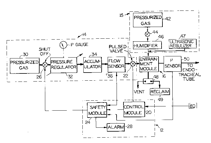
Ventilator 10 is an integrated modular system which generally
comprises a control unit 12, a high pressure gas supply unit 14, a
20 low pressure gas supply unit 15 and an entrainment module 16. The
control unit 12 comprises the electronic controls, safety system -
and the slectrical powsr supply for the ventilator. The high
pressure gas supply unit 14 comprises a source of high pressure
gas, a gas prsssure~regulation system and a valve subassembly for
producing controlled pulses of the gas derived from the high
pressurs source.~ Ths~low pressure gas supply unit 15 comprises a
source of low~prsssure~gss and a humidification system for the
gas. Ths sntrainmsnt moduls~l6 producss, from the pulses of high
~ ~ : 5
,
.:` .~ . ' ' : '
- :
7~
pressure gas and the humidified low pressure gas, the required
output of the ventilator. The gas flow lines are designated by
heavy lines and the electrical interconnections are desiynated by
thin lines in the drawing. The control unit 12 is connected to
the supply unit 14 via conventional separable electrical
connectors. The gas supply units 14 and 15 and entrainment
module 16 are interconnected by standard flexible hoses. The
above-mentioned modular units and their sub-units may be easily
connected and disconnected. The modular construction thus
facilitates maintenance of the ventilator and also provides a
ventilator which, to the extent required, may be easily
disinfected and sterilized as will be more fully apparent from
the discussion below.
With reference to Figure 1, the control unit 12 comprises an
electronic control module 20 which generates control pulses for
operating a solenoid actuated valve 22 in supply unit 14. The
control module 20 also provides input signals to an electronic
safety module~ 24. The safety module 24, in the manner to be
described below, controls an electrically operated shutoff valve
26 in the primary, i.e., high pressure, gas supply line and is
also connected to an alarm system 28.
A source of pressurized gas 30, which is typlcally in the
form of plural tanks containing compressed dry air,
oxygen/nitrogen, or oxygen/helium, is coupled via shutoff valve
26 and an adjustable pressure regulator 32 to an accumulator 34.
THe pressurized gas which appears at the output port of
accumulator~34 has a regul~ated substantially constant pressure in
the range~of~between 5 psi and 250 psi. The pressurized gas flows
': : : : :
.. ~ . . . .
.
" ' . '' ~
.
- ~z~s~
from the accumulator 34 via a Elow sensor 36 and valve 22 to
entrainment module 16. The flow sensor 36 provides an information
bearing input signal to safety module 24 whereby the nature of
the gas flow to the entrainment module 16 derived from high
pressure source 30 may be continuously monitored to provide a
means for actuating the alarm 28 in the event that the
aforementioned gas flow is not within the selected and required
operational limits of the ventilator. The alarm 28 is preferably
both an audible and a visual alarm. The safety module 24, which
is preferrably a microprocessor, is programmed to monitor the
operation of the ventilator, especially the primary gas flow to
the entrainment module and the pressure downstream of the
entrainment modu~le~ in order to determine whether the operating
parameters are within pre-established ranges. Should a monitored
parameter move into a range which is unsafe to the patient,
module 24 will command the closing of shutoff valve 26.
A secondary pressurized gas source 42, withln unit 15, is
coupled via a shutoff valve 44 to a humidifier 46. The output of
humidifier 46 is a bias flow of heated humidified gas which is
continuously supplied to the entrainment module 40 at a relatively
low pressure 8uch as 5 psi. The secondary gas source 42 is
typically in~the form of one or more tanks containing the same
gas as supplied by "high" pressure source 30. ~umidifier 46 is
preferably a cascade bubble humidifier and causes the bias flow
- to have approximately 100% relative humidity. In addition, an
ultrason~lc~nebulizer 47 may be employed to introduce a vapor mist
to thè~b~ias ~fl~ow of humidified gas. The stream of humidified gas
and vapor mist~, which is flowing at low velocity, is entrained in
.
. . ~ - . . . ........................ . .
.
~7~
module 16 by high velocity gas pulses, produced in the manner to
be described below, to form an output gas stream. As noted
abovet the output stream is supplied to the patient via an
endotracheal tube (not fully illustrated). The entrainment
module 16 also functions to receive gases exhaled by the patient.
Depending on the state of a two-way flow control valve 48, the
exhaled gas is either vented to the ambient atmosphere or
delivered to a reclamation unit 4g. A pressure sensor 50 may be
interposed in the gas path which extends from the entrainment
module to the endotracheal tube for sensing the pressure
immediately upstream of the endotracheal tube and providing a
corresponding input signal to the safety module 24 for insuring
safe operation of the ventilator.
With reference to Figure 2, the entrainment module 16
comprises a housing 51 which interiorly forms an entrainment
chamber 52. Houslng 51 is a generally T-shaped cylindrical
member which has an open output end. A fitting 54 at the output
end fluidically couples chamber 52 to a conduit 56 which leads to
or comprises the end of the endotracheal tube. Gas pulses,
- 20 produced by modulating the gas exiting accumulator 34 by means of
.
valve 22, are injected into the entrainment chamber 52 through a
nozzle 58. ~Nozzle 58 lS à convergent or convergent-divergent
nozzle and thus the velocity of the gas downstream of the nozzle
throat is high. Nozzle 5~8 extends axially into chamber 52
throug~h an~end wall of the housing 51~along the central axis of
the chamber. Nozzle 58~is~aerodynamically shaped to enhance
:: ,
entrainment~by directing the low pressure bias flow in the
- downstream~direction in chamber 52. Nozzle 58 thus preferrably
~: '
.~ . . . .. , . - , - . . , - . . . . . . .
.: :,, : .: ' ~. , '
.: . - , . . . : ;
. .,,
... ~ : . . .
121~
has a forwardly tapering converyent external profile. An inlet
leg 62 and an outlet leg 64 protrude radially at diametrically
opposite locations of housing 51. Legs 62 and 64 are
substantially identical and are equidistant from the centrally
disposed nozzle 58. Inlet leg 62 functions as a connector
structure for coupling to a conduit for supplying the low
velocity bias stream of humidified gas to the entrainment chamber
52 via port 66 as illustrated by the arrows in Figure 2. The
humidified gas is continuously supplied to the entrainment
chamber. During an inspiratory phase of the ventilation cycle,
humidified gas is entrained by a high velocity gas pulse injected
into chamber 52 via the nozzle 58 and propelled axially through
the chamber to conduit 56 and thence to the patient via the
endotrachial tube. The ventilating gas pulses delivered to the
patient will be comprised primarily of humidified gas supplied
via inlet leg 62 entrained by the pulses of dry gas supp]ied via
nozzle 58. Accordingly, the patient will receive gas having the
highest possible relative humidity.
During the expiratory phase of the ventilation cycle, the ~ -
gas exhaled by the patlent returns via conduit 56 to the
entrainment~chamber 52. The exhaled gas is entrained by the low
velocity bias~flow and is thus discharged through discharge port
68 which~leads to~outlet leg 64. Leg 64 is coupled to a conduit
for conducting tbe exhaled gas and excess humldifled gas to valve
:
48. The expired carbon dioxide ~rom the patient is discharged
through port 6B in part due to the driving force of the bias flow
of humidifled gas which prevents the exhaled gases from entering !
port 66~. ~
7X~
The entrainment of the humidified gas by the high velocity
pulses or slugs of primary gas is facilitated by the convergent
exterior shape of nozzle 58 which, as mentioned above, functions
as a flow control surface. The entrainment of the humidified gas
is improved by the placement o~ the outlet 60 of nozzle 58 at an
axial location of the chamber which is proximate the downstream
axial terminus of the inlet port 66. Consequently, the high
velocity pulse is injected into the chamber at a location
slightly downstream from the entry of the humidified gas. As
should now be obvious, the continuous supply of the low pressure
humidified secondary gas functions to alternately supply
humidlfied gas for entrainment and to remove the expired carbon
dioxide from the ventilator unit without the use of any mechanical
valves which would otherwlse tend to deteriorate the entrainment
effects and, thus, would result ~n lower tidal volumes.
A low compIlant tube connects nozzle 58 to the solenoid
a~tuated control valve 22. Valve 22 is a bi-state valve having
an open and closed position. The command signals generated by
control module 20 and applied to the solenoi~ of valve 22
determine the frequency and duration of the gas pulses delivered
to nozzle 58. Thus,~ valve 22 is cyclically opened and closed for
selected time lntervals to interrupt the flow of pressurized gas
to nozzle 58 to thereby produce the desired gas pulse train
characteristics to provide optimum treatment for the patient.
The characteristics of the train of pressurized gas pulses
produced by valve 22 may best be appreciated by reference to
Figures 4a, 4b and 4c. The horizontal axes represent the time in
milliseconds and the vertical axes represent the flow rate of the
.. 10
" : :
.. . . .
S44
high velocity ventilation ~as exiting nozzle 58. The letter T
represents the time of one ventilation cycle, i.e., the time of
a inspiratory phase plus the time of a following expiratory
phase. The symbol tl represents the time interval d~ring which
valve 22 is open. For each of the graphs of Figure 4, the time
interval in which valve 22 is opened, i.e., the inspiratory time,
is 3~ percent of the ventilation cycle T. The graph of Figure 4a
represents the pulse train characteristics when valve 22 is
opened and closed at a 5 Hz. frequency. Graph 4b represents the
pulse characteristics when valve 22 is opened and closed at a 10
Hz. frequency. ~igure 4c represents the pulse charactistics when
valve 22 is opened and closed at a 20 Hz. frequency.
The volume of gas supplied by the valve per breath is equal
to the area under the flow rate-time curve of the graphs of
Figure 4. The solid lines represent the flow characteristics for
ventilator 10. The broken llnes represent the flow
characteristics for a ventilator which does not incorporate a
feature for reducing the time required for the valve to change
states in accordance with the present invention. It will be
appreciated that the depicted curves have a trapezoidal shape
rather than a square wave shape doe to the incremental time
interval required for valve 22 to change from one state to
another, i.e., from a fully closed state to a fully open state
and vice versa. In ~the prior art, at high pulse frequencies
there was insufficient time for the valve to open completely
before recslpt of a "close" command. Accordingly, the triangular
flow~pattern indicated~ by the broken lines of Figure 4c resulted.
A flow pattsrn ag represented by the broken line showing of
- . . .,: . - :
.- ' - : '' :. ` . ' '' ' : ' , '
. ~ . ,
: . .
--` lZ~1~5~L
Figure 4c leads to a drastic reduction in the tidal volume, i.e.,
the volume of gas supplied to the patient, duriny the inspiratory
phase. Consequently, in order that sufficient tidal volumes be
supplied at high ventilation frequencies, the valve must be
caused to react quickly to "open" commands and should remain open
for a significant portion of the inspiratory phase.
With reference to Figure 3, valve 22 is opened and closed by
means of solenoid 70 which is responsive to command signals
generated by the control module 20. Control module 20 includes a
square wave generator 72. ~ resistance capacitance network 73 is
adjustable ln the conventional manner to vary the time constant
of and thus the output frequency of square wave generator 72.
The square wave output signal of generator 72 is applied to a
timer circuit 74. Referring jointly to Figures 3 and 5, an
adjustable voltage magnitude selection circuit and an adjustable
duty cycle selection circuit are coupled to timer 74 to cause the
timer to provide an output waveform having a selected amplitude
(voltage Vl), pulse wldth (time tl~ and frequency f. Voltage V
is selected to be the minimum solenoid holding voltage required
to sustain valve~22 in the~opened position. This voltage is
typically lower than the voltage necessary to cause the solenoid
to open the valve. Use of a low voltage to maintain the valve
open reduces the closlng ~time ~for the valve. The closing time is
further reduced by~a~ short duration large negative voltage spike
:
-V2 which~is generated at the end of the inspiratory phase of the
cycle upon~removal of the timer 74 output voltage ~rom the valve
~~ solenoid.~ Tim~e~tl is sel~ected to provide the optimum inspiratory
`` tlme~per ventllation cycle. Frequency f is selected to provide
, ~
12
- , - .: :' ', '- , : :, ', - . : , .
' ~ ' ' , , . ' !
~21Y~S~
the optimum ventilation frequency in accordance with the
condition of the patient. The square wave from circuit 72 is
also applied to an overdrive timer circuit 76. The overdrive
timer circuit is also adjustable to generate a second waveform
having a second amplitude ~voltage V3-Vl) and second pulse width
(time t2) with the same frequency f as and in phase with the
waveform provided by timer 74. Voltage V3-Vl and time t2 are
selected to reduce the valve opening time as detailed
hereinafter. The two waveforms are combined, as represented
lo schematically by summing circuit 77, and applied to solenoid 70.
The waveform applied to solenoid 70 is illustrated in Figure 5.
The period of one opening and closing phase or cycle of valve 22,
and hence the ventilation cycle, is given by time T. By applying `
the overdrive voltage V3-Vl to the solenoid, the overdrive
voltage having an amplitude which is at least three times as
great as~the holding voltage Vl, a greater electromagnetic force
is generated, and the opening time of the valve is significantly
reduced.~ Thus, the tidal volumes produced by the ventllator at
high frequencies is not substantially reduced by the time
required for the valve to ch;ange its state. As noted above, in
the graphs of Figure~4, the broken~lines illustrate generally the
pulse characteristics without application of the overdrive
voltagè to the solenoid and the solid~lines represent the pulse
- characterlstics of the ventilator when the foregoing described
over~drive~vol~tage is applied from the control module.
It~wil~l be appreciated that the ventilator 10 is operated by
selecti;ng~an optimum~frequency and duty cycle, i.e., the ratio of
~inspiration~tlme to ventllation cycle time, for the condition of
` 13
:., ~ . ;. . . . . . . :. .
.: . . ~ . ,. , , :
the patient. The tidal volume of ventilation yas supplied to the
patient is a function of pulse frequency and duration as well as
gas pressure. Pressure regulator 32 regulates the pressure by
conventional means. The control module ~unctions to
electronically control valve 22 to provide the optimum ventilation
characteristics. The latter characteristics may change over the
treatment period and the ventilator of the present invention is
capable of manual or automatic readjustment in accordance with
varying patient requirements. In actual practice, the control
and safety modules may be a single subassembly including a
programmable microprocessor and the operational mode may be
entered from a keyboard and/or selected from preprogrammed data.
Since this can be accomplished without disconnecting the patient
from the ventilator, trauma is avoided that could otherwise
occur. It should be appreciated that since the ventilator is of
modular construction, sterilization and maintenance of the unit
can be relatively easily achieved. The entrainment module 16 has
no moving components and thus may be easily disconnected from the
ventilator for sterilization and/or replacement.
The present invention has the flexibility, particularly
.: .
operational parameters which are adjustable over broad ranges,
which enables its use in a synchronous intermittent mandatory
ventilation (IMV) mode. The IMV mode will be selected, via the
microprocessor based control module 20, when it is desired to
attempt to wean a patient from the ventilator. In the IMV mode a
pulse,~at a freguency less than the normal breathing rate, will
be provided by a~clock in the microprocessor to trigger the
generation of~command signals for the valve 22 solenoid. A
14
- . . ~ , , .
.. . . . . .. . .
- ~ . ., ~ ... .
. . . ,: . - , . . .
. : . . . . ~ .. :
. -: : . , . , ~
:~L2~
sensor 80, which could be a pressure sensor in the enc~otracheal
tube, will sense spontaneous breathing by the patient and provide
signals commensurate therewith which are inputted to control
module 20. The valve 22 will open at the selected frequency
except each time spontaneous exhalation is sensed, in which case
the opening of the valve will be delayed until the end of
exhalation and the clock will be reset to zero. The present
invention may also, with the removal of the entrainment module 16
and low pressure gas supply unit 15, be employed in the case of a
transcutaneous cricothyroidalostomy. In emergency situations,
for example under battlefield conditions or in the case of medical
technicians at the scene of an accident, a patient experiencing
breathing difficulty cannot be provided with an endotracheal tube.
That is, the proper insertion of an endotracheal tube may require
as long as one-half hour, requires good lighting and requires a
highly trained medical professional. The present invention, with
the entrainment module removed but a nozzle similar to nozzle 58
retained, can be utilized by medical technicians in the following
manner. A needle with associated catheter will be inserted into
the trachea,~the needle will then be withdrawn and the nozzle
then inserted into the trachea via the catheter. Jet ventilation
may then be started with exhalation being via the patient's mouth
and/or nose.
While preferred embodiments of the invention have been set
forth for purposes of~illustration, the foregoing description
should not be~ deemed a limitation of the invention disclosed
` herein.~ Accordingly, various modiEications, adaptations and
- alternatives~may occur to~one skilled in the art without departing
from the spirit and the scope of the present invention.
-` 15
- .: , .
.. ,:. .. . . . . , . . ::
: . . .: . .
- , ~ , . .
.
- . ' ' , . . ' . ' . ~ ' ' ' ' . . ~