Note: Descriptions are shown in the official language in which they were submitted.
77~
~A~T~~01JNT~ OF T~IE~NTTO~
rhis invcntion relatcs to seats which incl~ldc vibration compcnsating
seat suspcnsions.
Seats of vehicles such as tractor-trailer trucks are subject to
substantial vibration. Severe vibrations occur as vehicles travel rough
road surfaces. A majority of seats now made for operators of such
vehicles includc vibration compensating suspensions beneath the seats.
Such suspensions are in addition to the vehicle suspension systems which
interpose the wheels of the vehicle and the vehicle bodies. A pervasive
seat suspension is the parallelogram suspension. This suspension takes its
name from a parallelogram linkage which is central to the suspension.
The parallelogram suspension provides purely vertical movement of the
seat during vibration.
A suspension much improved over the parallelogram suspension is the
suspension Or United States Patent No. 3,711,149. The suspension of this
patent is a "knee-pivoting" suspension. This suspension takes its name
from a pivoting of the seat about the front of the seat during vibration.
The pivoting is in the area of the knee of the seat occupant. Such
pivoting is desirable because it minimizes movement of the lower leg
during vibration. The knee of the seat occupant flexes as the seat
pivots, maintaining foot contact with vehicle controls. While lower leg
movement is minirnized, the seat also improves the quality of the ride of
the occupant by eliminating the tendency of the upper body of the
occupant to strike the back of the seat during rebound from vibration
(commonly called "back-slapping").
~2~37~73~
~IJMMAI~y QF r~IE IllV131~iTlO
The present invcntion is a vibration compensating vchicle seat
suspension which is ;mproved over the parallelogram suspension and also
improved over the knee-pivoting suspension. The invention combines the
best of both such suspensions. The invention combines vertical movement
of the seat during vibration with knee-pivoting movement of the seat
during vibration. As a result of a severe change of road surface, for
example, a tractor-trailer driver will have his seat pivot downward
beneath him, about a pivot in the area of the knee of his operating leg.
Back-slapping action on rebound will be minimized. At the same time,
the front of his seat will move slightly downward beneath him. Contact
of the foot with the vehicle controls will not be sacrificed. At the same
time, howeve}, comfort will increase, because the knee of the operating
leg will be cushioned by the slight vertical movement and the body will
be moved more uniformly.
In a principal aspect, then, the invention is an improved vibration
compensating vehicle seat suspension. The invention includes a vibration
linkage which comprises a hori~ontal pivot for pivoting of the seat and a
sublinkage for simultaneous vertical movement of the seat.
Three embodiments of the invention are included hereafter as part
of the invention. By example, a first of the embodiments is a suspension
as described, and comprising, in detail, a base including a first slide
member. A second slide member is slidably mounted to the f irst slide
member. A seat support member is pivotably mounted to the second slide
member, while a link member is pivotably mounted to the base. A first
slide actuator member is located on the link member. A second slide
, ~ - - ' - -
actuator meml~cr is pivotably mounted to the basc, engage(t by the rirst
slicle nctllator member and engages the first sliclc member. Vibration
causcs thc scat support mcmber and lin~ mcmbcr to pivot. The pivoting
of the link member causes pivoting of the f;rst slide aetuator member,
which pivots the second slide actuator member. The pivoting of the
seeond slide actuator member drives the second slide member down
relative to the first slide member and the base. Overall motion is
pivoting of the seat combined with vertical sliding of the seat front.
This embodiment, the other two embodiments, and the full range of
advantages of the invention will be best understood upon a full reading
of the detailed description of the preferred embodiments of the invention,
which follows a brief description of the accompanying drawing.
~ 2 8 ~
BRll~F DESCRIP I`ION OF THE DR~
In the detailed description which follows, the preferrecl embodiments
of thc invent;on are described with reference to the accompanying
d,~awing. Briefly, the drawing consists of ~6n figures, or views. These
figures are as follows:
FIGURE I is a perspc ctive view of a seat according to the
invention;
FIGURE 2 is a perspective view of the seat of Figure 1, with the
cushions partially cut away to reveal that the seat is made according to a
first preferred embodiment of the invention;
FIGURE 3 is an exploded perspective view of portions of the first
preferred embodiment of the invention;
FIGURE 4 is a front elevation, detail view of the portion of the
first preferred embodiment shown in Figures 2 and 3;
FIGURE 5 is a side elevation view of portions of the first preferred
embodiment of the invention, in a static state;
FIGURE 6 is a side elevation view of the same po}tions of the first
preferred embodiment of the invention as in Figure 5, in motion due to a
vibration of the vehicle (not shown) in which the seat is located;
FIGURE 7 is an exploded perspc ctivc view of portions of a second
preferred embodiment of the invention.
f~.',`~
FIGURE 8 is an exploded perspective view of portions of a ~e~cl
preferred embodiment of the invention;
FIGURE 9 is a side elevation view of portions of the
preferred embodiment of the invention, in a static state; and
~ 2~7~;'9~L
I~IGURE 10 is a sidc clcvntion vicw of thc snmc port;ans of thc
.5t~R* pr~f~rrcd cmbodiment of tho invcntion as in Fig~lrc 9, ;n motion
duc to a vibration of thc vchiele (not shown) in which the scat is
locntcd.
'3~ 3tj1J;j~
DET~II.ED DE~C~lrTlON ~)~ T~IE PlREFERl~ED_MI~ODlMENT~
Referring to Figure 1, the invention is an improvement in a
suspension for a vehicle seat 10. For illustration, the back cushion 12
and seat cushion 14 of the seat 10 are shown, mounted above a base IG
to a vehicle body (not shown). A mechanism 18 interposes the seat
cushion 14 and the base 16. The cushions 12, 14 are filled with foam
rubber and covered with leather. The back cushion and seat cushion are
contoured to include wings for the greater comfort and stability of an
occupant. (While the contour and materials of the seat 10 are specified
for illustration, an advantage of the invention is that the invention limits
neither the shape nor materials of the seat with which it is employed.
The seat incorporating the invention may be a comfortable seat and an
aesthetica11y pleasing seat.)
Referring to Figure 2, the mechanism 18, as with the first
preferred embodiment illustrated in Figure 2, is contained in the area
under the seat. The mechanism 18 occupies substantially the same space
,as the parallelogram suspension of the past, or the knee-pivot suspension
Ai of U.S. Patent 3,711,149~r~.
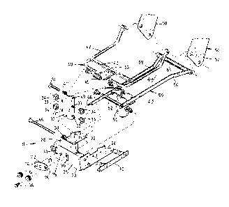
Referring now to Figure 3, a first preferred embodiment of the
invention 11 includes a plurality of components. A chassis housing 20 is
linked to the base 16 for conventional vertical and forward/backward
static positioning of the seat 10 to suit the size and desires of an
occupant. The housing 20 includes two upright, parallel side plates 22, 24
joined by an upright face plate 26. The plates are welded metal plates,
and the face plate 26 forms rearwardly directed flanges at its upper and
8t~
lower edgcs to which thc sidc platcs arc joincd for incrcasc(l stability of
the asscmbly.
An outcr stanchion 28 is wcldcd atop the facc platc 26. Thc OUtCI
stanchion has a "C" shape ;n horizontal cross-section, thereby forrning a
vertically oriented, rectangular stanchion passage 30. A plurality of pins,
slots and openings are defined on the chassis housing 20, as will be
described hereafter.
An inner stanchion 32 includes a vertical face and two side flanges,
formed integrally in the inner stanchion. The inner stanchion 32 has
four pins 33 extending horizontally from the side flanges, two per side
flange. A slide block 34 is fitted on each pin. The inner stanchion 32
with four slide blocks 34 is slidably movable within the stanchion
passage 30 of the outer stanchion 28. The slide blocks 34 separate the
inner stanchion 32 from direct sliding contact with the outer stanchion
28, and smooth the vertical sliding movernent of the inner stanchion 32.
A slot 36 is defined in the face plate 26 of the chassis housing 20,
beneath the outer stanchion 28. The slot is narrow horizontally, and
extends vertically. The slot 36 receives a slide pin 3~ mounted on the
bottom of the face of the inner stanchion 32. The movement of the slide
pin 38 is limited by the vertical extent of the slot 36. Thus, the slot 36
is a slide control slot, and the pin 38 is a slidc control pin. Together,
the slot 36 and pin 38 form one form of a means for limiting the extent
of the vertical sliding movement of the inner stanchion 32 relative to the
outer stanchion 28.
A welded steel cushion tube assembly 40 is mounted to the inner
stanchion 32 for pivoting about a first, horizontal axis. The cushion tube
assembly includes a pair of outer cushion tubes 42, 44 extending from a
3~7~3~
forward, ccntral cusllion pivot tube 46. 'I he CUShiOII pivot tube ~16 is
mountcd to the inncr stnnchion 32 at n pair of pivot openillgs 47, 49
adjacellt the top of the inner stanchion 32. Plastic bearings interpose
the cushion pivot tube 46, the inner stanchion 32 and a pivot pin Sl, and
smooth the pivoting of the cushion pivot tube 46 relative to the inner
stanchion 32 and pivot pin 51. A reinforcing bar 48 joins the outer
cushion tubes and a central plate 53 back of the cushion pivot tube 46,
to strengthen the assembly 40. The outer cushion tubes 42, 44 extend
rearward from the reinforcing bar to plate steel arm brackets 50, 52 of a
back cushion frame 54. Bushings, bearings and fasteners such as bolts
(not shown) mount ~he arm brackets 50, 52 on the cushion tubes 42, 44,
respectively, for pivoting motion of the arm brackets and back cushion
about a second, horizontal axis.
A welded steel pivot arm assembly 56 underlies the cushion tube
assembly 40. The pivot arm assembly 56 extends in two mirror-image
arms 58, 60 formed of plate, from a forward pivot arm pivot tube 62 to a
rear pivot arm pivot tube 64. The forward pivot arm pivot tube 62 is
pivotably mounted via a pivot shaft 65 to the side plates 22, 24 of the
chassis housing 20 for pivoting about a third, horizontal axis. The rear
pivot arm pivot tube 64 is mounted to the back cushion frame arm
brackets 50, 52 for pivoting about a fourth, horizontal axis. An air
spring 66 is mounted under a plate 67 extending between the arms 58, 60
intermediate the pivot tubes 62, 64.
An arm 58 of the pivot arm assembly 56 includes a steel slide
acl,uator pin 68. The pin 68 extends beyond and forward of the front
: 6~Z
AL pivot arm pivot tube ~4, through a pin slot 70 in the face plate 26 of the
chassis housing 20. The pin slot 70 is narrow horizontally, and extends
91
vertically. Thc pin 68 cn~ag&s a control brackct 72, within a pin rcccss
74.
The control bracket 72 ;s pinned to the chassis housing facc plate
26, for rocking motion about a fifth hori~ontal a~cis pcrpendicular to the
first through fourth axes (which are parallel to each other). The bracket
72 is pinned to a rocker pin 75, which lies between the pin slot 70 and
the slidc control slot 36. Opposite the slide actuator pin 68, the slide
pin 38 engages the bracket 72, within a second recess 76. Referring to
Figure 4, when the slide actuator pin 68 is at the bottom of the pin slot
70, the slide pin 38 is at the top of the slide control slot 36, and the
inner stanchion 32 is up. When, as in phantom, the slide actuator pin 68
is at the top of the pin slot 70, the slide pin 38 is at the bottom of the
slot 36, and the inner stanchion 32 is moved down.
Rcferring to Figures 5 and 6, the slide actuator pin 68 is at the
bottom of the pin slot 70 when the cushion tube assembly 40 and pivot
arm assembly 55 are in static positions, as shown in Figure 5. The slide
actuator pin 68 is at the top of the pin slot 70 when the cushion tube
assembly 40 and pivot arm assembly 56 are in vibrated positions, as
shown in Figure 6.
Referring again to Figure S, the air spring 66 shown in Figure 3
causes the mechanism 18 to occupy and return from vibration to the
static position shown in Figure S. The inner stanchion 32 is in a static,
raised position relative to the outer stanchion 28. The cushion tube
assembly 40 and pivot arm assembly 56 are in static positions suitable to
comfortable, preferred seat positioning for an operator.
Vibration of a vehicle in which the seat 10 is located causes
movement from the static positions of lFigure S. Referring to Figure 6,
vibra~lon causes ~he cushion tube assembly ~0 to plvot lowrlward
about the pivot openings 47, ~ o~ the inner stanch:lon 32, as
depicted by arrow 77. Movement Oe the back cushlon ~rame 5~ and
pivot arm assembly 56 is caused by movement of the cllshion arm
assembly 40~ The pivo-t arm assembly 56 pivots downwarcl about the
shaft 65 on the chassis housing 20, as depicted by arrow 78. The
back cushion frame 54 maintains its angle to the horizontal as it
moves.
The pivoting of the pivot arm assembly 56 causes upward
movement of the slide activator pin 68. As described above, the
inner stanchion 32 is moved down. The consequence is that upon
vibration, the seat 10 pivots down and simultaneously, the front,
knee area of the seat moves linearly down. Lengths and pivot
locations are selected such that total linear movement of the seat
front is about one inch. The air sprin~ 66 causes position
recovery, i.e., causes the seat to rebound from vibration.
As now may be understood, the first preferred embodiment
of the invention includes a vibration linkage for a seat. The
linkage includes, in this preferred embodiment, as one possible
form of the linkage, the inner stanchion assembly, cushion tube
assembly, pivot arm assembly, and portions of the back cushion
frame. The linkage has a horizontal pivot at the top of the inner
stanchion for pivoting of the seat and a sublinkage comprising the
slide actuator pin, control bracket and inner stanchion, for
simultaneous vertical movement of the seat. The inner stanchion
forms a vertical slide proximate the seat front along which the
.~
~ ~ ~t~7 ~
hori~ontal pivot is 51icl; the outer ancl inner stanch:lolls
constitute one possible fo.rm of flrst and secontl s;li.cle melllbers,
respectlvely.
Attention is now directed to the second preferred
embodiment 110. Some elements of the second preferred embodiment
are identical to
'~ lOa
. ~
3 ~ 7 ~3~
clcments of thc f;rst prefcrrcd cmbod;ment. Whcrc idontical, thc
elcments havc rcfcrence numcrals ;dcnt;cal to thc l'irst prcfcrrcd
embodimcnt. Rcferring to Figure 7, the sccond preferred embodimcnt
includes an inner stanchion 32 with slide blocks 34 in an outer stanchion
28, A cushion tube assembly 40 pivots on the inner stanchion 32. A
pivot arm assembly 156, lacking a slide actuator pin 68, mounts on a
chassis housing 120S lacking slots 36, 70 or rocker pin 75. A coil spring
112 substitutes for the slide actuator pin 68, rocker pin 75 and associated
elements. The coil spring 112 is situated beneath the inner stanchion 32,
between the inner stanchion 32 and the chassis housing 120. The coil
spring 112 spring biases the inner stanchion 32 to a static position
identical to the position of Figure 5. As vehicle vibration overcomes the
spring force, the coil spring 112 provides downward movement of the
seat, simultaneous to pivoting movement of the seat to a position
identical to the position of Figure 6.
Attention is now directed to the third preferred embodiment 210.
The third preferred embodiment is the current commercially preferred
embodiment, and differs more from the first preferred embodiment than
does the second preferred embodiment. Referring to Figure 8, a pivot
tube 246 of a cushion arm assembly 240 is pivotably mounted directly on
an outer stanchion 228. There is no sliding of the pivot tube 246.
Inner cushion arms 241, 243 extend rearward and outward of the
pivot tube 246 to pivoting attachment to the arm brackets 250, 252 of a
back cushion frame 254. Outer cushion arms 242, 244 attach with the
inner cushion arms to the arm brackets, and extend forward to direct,
fixed attachment to the seat cushion 14 (shown in Fig. 1). A front
cushion support bracket 280 is independent of, i.e., not attached to any
~ ~3~79~
part o~` the cusllion arm nsscmbly 240. Thc br~ackct 280 ~Ittncllcs (lircctly
to thc sent cushion 141 as do the outcr arms 242, 244. Togethcr with thc
nrms 242, 244, the braclcct 280 supports thc scat cushion 14. Unlikc
cushion tube assembly 40 of the first preferred embodiment, the inner
arms 241, 243 are not directly attached to and do not directly support
the seat cushion 14.
A pivot arm assembly 256 mounts to a chassis housing 220 and arm
brackets 250, 252, in the same manner as assembly 56 mounts to housing
20 and arm brackets 50, 52.
In contrast to the first preferred embodiment, cushion bracket arms
290, 292 are pivotably linked to the arms 258, 260 of the pivot arm
assembly 256, between the assembly connection to the chassis housing and
the arm brackets. The arms 290, 292 are also pivotably linked to the
front cushion support bracket 280.
Referring to Figure ~, the elements of the third preferred
embodiment occupy static positions of desirable positioning of a seat.
o
Referring to Figure ~ vibration causes downward pivoting of the inner
cushion arms 241, 243 and of the arms 258, 260 of the pivot arm assembly
256. Downward pivoting of thc arms 258, 260 causes downward movement
of the arms 290, 292, and with them, the front cushion support braclcet
280. Because the cushion is attached to the bracket 280, downward
movement of the bracket 280 causes downward movement of the seat
cushion, along its front. Seat motion is substantially identical to seat
motion in the first preferred embodiment, despite difference of
mechanism.
As now may be understood, the seat of the third preferred
embodiment includes a vibration linkage of a plurality of links. The inner
37~9~
.
cushion arms 241, 243 constitute one possible form of first link
members pivotably mounted to the seat base by mounting to the
chassis housing 220. The outer cushion arms 290, 292 constitute
one possible form of second link members, and the pivot arm
assembly arms 258, 260 constitute one possible form of third link
members. Pivots are formed as follows: (1) between the first
link members and the seat base, first pivots; (2) between the
first link members and back cushion frame arm brackets 250, 252,
second pivots; (3) between the second link members and the seat
cushion, at the front cushion support brackets, third pivots; (4)
between the third link members and the second link members, fourth
pivots; (5) between the third link members and the seat base,
fifth pivots; and (6) between the third link members and the arm
brackets, sixth pivots.