Note: Descriptions are shown in the official language in which they were submitted.
` ` ~.2~02~, QM 34371
-- 1 --
DIFFERENTIAL GAS PRESSURE CONTROL DEVICE
This invention relates to a differential gas
pressure control device for use with an electrolytic cell
which comprises an anode compartment in which a gas is
generated and a cathode compartment in which a gas is
generAted. The differential pressure control device ls
partlcularly suitable for use with an electrolytic cell
ln whlch chlorine and hydrogen are generated ln the anode
and cathode compartments respectively of the cell by the
electrolysis of aqueous alkali metal chloride solution,
although use of the control dev~ce is not restricted to
cells used for such electrolysis and it may be used with
any electrolysis in which gases are generated in the
anode and cathode compartments of the cell, eg in the
electrolysis of water in which oxygen is generated in the
anode compartments and hydrogen is generated in the
cathode compartments.
Electrolytic cells are known comprising an anode
or a plurality of anodes and a cathode or a plurality of
cathodes with each anode being separated from the
ad~acent cathode by a separator which divides the
electrolytic cell into separate anode and cathode
compartments. The anode compartments of such a cell are
provided with means for charging electrolyte to the cell,
suitably.from a common header, and with means for
removing products of electrolysis from the cell.
Similarly, the cathode compartments of the cell are
provlded with means for removing products of electrolysis
from the cell, and optionally with means for charging
water or other fluids to the cell, suitably from a common
header.
In such electrolytic cells the separator may be
a porous hydraulically permeable diaphragm or it may be a
substantially hydraulically impermeable ionically perm-
1~ Oo
-- 2 --
selective membrane, e.g. a cation permselective membrane.
Such electrolytic cells are used on a vast scale
throughout the world to produce gaseous chlorine, gaseous
hydrogen, and aqueous alkali metal hydroxide solution by
the electrolysis of aqueous alkali metal chloride
solution.
Where aqueous alkali metal chloride solution is
electrolysed in an electrolytic cell of the diaphragm,
type the solution is charged to the anode compartments of
the cell, gaseous chlorine produced by electrolysis is
removed from the anode compartments, depleted solution
passes through the diaphragms to the cathode compartments
of the cell, and gaseous hydrogen and alkali metal
hydroxide produced by reaction of alkali metal ions with
water are removed from the cathode compartments, the
alkali metal hydroxide being in the form of an agueous
solution which also contains alkali metal chloride.
Where aqueous alkali metal chloride solution is
electrolysed in an electrolytic cell of the membrane
type the solution is charged to the anode compartments of
the cell and gaseous chlorine produced in the
electrolysis and depleted alkali metal chloride solution
are removed from the anode compartments, alkali metal
ions are transported across the membranes to the cathode
compartments of the cell to which water or dilute alkali
metal hydroxide solution is charged, and gaseous hydrogen
- and alkali metal hydroxide solution produced by the
reaction of alkali metal ions with water are removed from
the cathode compartments of the cell.
In such electrolytic cells the operational life of
the separator is governed to some exter,t by the absolute
pressures of the gases produced in the anode and cathode
compartments of the cell, but it is governed in
particular by the differential pressure between these
gases, and by variations of this differential pressure.
~L~8~3025
This is particularly the case where the separator is an
ionically permselective membrane. For example, in an
electrolytic cell which is eguipped with such a membrane
and in which gaseous chlorine and hydrogen are produced
by the electrolysis of agueous alkali metal chloride
solution optimum membrane life and performance is
obtained when the hydrogen gas pressure in the cathode
compartments of the cell slightly exceeds the chlorine
gas pressure in the anode compartments of the cell. This
differential pressure forces the membranes towards the
anodes of the electrolytic cell and reduces the amount of
movement of the membranes. Movement of the membranes,
which may be caused by variations in this differential
pressure, and in particular excessive movement of the
membranes which may be caused by reversal of the
differential pressure, may result in mechanical or
chemical damage to the membranes. Such mechanical damage
may take the form of pin-holes, cracks or blisters in the
membrane, or it may even result in complete rupture of
the membrane and consequent mixing of the gaseous
hydrogen and chlorine with potentially dangerous
conseguences. Although use of a high differential
pressure of hydrogen over chlorine would cause the
membranes to be firmly positioned against the anodes the
use of such a high differential pressure is not
acceptable as forcing the membranes firmly against the
anodes may itself result in damage to the membranes.
Where the separator is a porous hydraulically
permeable diaphragm it is particularly important to
maintain the desired differential gas pressure in order
to minimise or prevent passage of gases across the
diaphragm and conseguent mixing of hydrogen and
chlorine.
In conventional practice the differential pressure
between the gases produced in the anode and cathode
~28~3025
compartments of an electrolytic cell is controlled by
converting the gas pressures into an electronic signal by
means of transducers, processing the signals in a control
device which generates a corrective signal, and passing
the corrective signal to an appropriate control
transducer which may, for example, control appropriate
valve means operation of which restores the differential
pressure to the desired value. Such a control system may
operate ln a step-wise manner, that is a step-wise rather
than a continuous change in differential gas pressure may
be effected, and there may be a finite time delay between
a change in differential pressure and correction thereof.
However, in operation of some electrolytic cells there is
a need for a rapidly acting control means which provides
a virtually continuous control of the differential gas
pressure in order that any undue time delay in the
correction of a change ln differential gas pressure
should not result in damage to the separator in the
electrolytic cell, which is particularly necessary where
the separator is an ion-exchange membrane, or in
undesirable mixing of gases.
The present invention provides a differential gas
pressure control device which is responsive to variations
in the pressures of the gases produced in both the anode
and cathode compartments of an electrolytic cell, which
is essentially simple in construction and in operation,
and which provldes a rapid corrective response to any
change in the differential gas pressure from the desired
value of the differential gas pressure.
According to the present invention there is
provided a differential gas pressure control device for
an electrolytic cell which cell comprlses at least one
anode compartment containing at least one anode at which
in operation a gas is generated, at least one cathode
compartment containing at least one cathode at which in
~ 8~3025
operation a gas is generated, a separator positioned
between each anode and adjacent cathode, a pipe leading
from the anode compartment(s) of the cell through which
ln operation anode gas passes, and a pipe leading from
the cathode compartment(s) of the cell through which in
operation cathode gas passes, ln which the control device
comprises a moveable flow controller positioned so as to
control the flow of anode gas in said pipe and a moveable
flow controller positioned so as to control the flow of
cathode gas in said pipe, in which the flow controllers
are operatively connected, and in which in operation the
anode and cathode gases independently act upon the flow
controllers which control the flow of cathode gas and of
anode gas respectively.
In operation of the differential gas pressure
control device of the invention the gas which is produced
in the cathode compartment(s) of the electrolytic cell,
that is the cathode gas, acts independently upon the
moveable flow controller which controls the flow of gas
which is generated in the anode compartment(s) of the
electrolytic cell, that is the anode gas. Similarly, the
gas which is produced in the anode compartment(s) of the
electrolytic cell, that is the anode gas, acts
independently upon the moveable flow controller which
controls the flow of gas which is generated in the
cathode compartment(s) of the electrolytic cell, that is
the cathode gas. Thus, for example, when the pressure of
the anode gas which is produced in the electrolytic cell
rises relative to the pressure of the cathode gas such
that the differential between the pressures of the anode
gas and cathode gas rises above the desired value the
anode gas acts upon the flow controller which controls
the flow of cathode gas so as to restrict the flow of
cathode gas and cause a rise in the pressure of cathode
~288025
gas produced in the electrolytic cell thereby restoring
the differential pressure between the anode and cathode
gases.
Similarly, when the pressure of the cathode gas
which is produced in the electrolytic cell rises relative
the pressure of the anode gas such that the differential
between the pressures of the anode gas and cathode gas
decreases below the desired value the cathode gas acts
upon the flow controller which controls the flow of anode
gas so to restrict the flow of anode gas and cause a rise
in the pressure of anode gas produced in the electrolytic
cell thereby restoring the differential pressure between
the anode and cathode gases to the desired value.
In US Patent 2 695 874 there is described an
electrolytic cell which comprises a permeable diaphragm
which divides the cell into separate compartments in
which hydrogen and oxygen respectively are generated by
electrolysis, and which is provided with a control means
for maintaining a desired pressure dlfferential between
these gases.
The control means comprises two gas separators
into which hydrogen and oxygen respectively are
discharged and which are connected by a liquid-filled
U-tube, a pressure control valve which controls the flow
of hydrogen from the gas separator, and a float
controlled valve which is in contact with the liquid in
the U-tube and which controls the flow of oxygen from the
gas separator.
In operation excess pressure of hydrogen in the
gas separator causes the pressure control valve to be
activated, hydrogen to be released, and the pressure of
hydrogen to decrease. Decrease in the hydrogen gas
pressure results in flow of liquid in the U-tube towards
the hydrogen gas separator with conseqent movement of the
float and the valve in the oxygen separator and release
s025
-- 7 --
of oxygen gas. The conseguent decrease in oxygen gas
pressure restores the differential gas pressure.
The differential pressure control means of the US
Patent is quite unlike the device of the present
invention.
The flow controllers may comprise at least one
flexible membrane, which is desirably non-porous, that is
non-permeable to gases generated in the electrolytic cell
and with which it comes into contact. It is also
desirable that the membrane is resistant to chemical
attack by the gases generated in the electrolytic cell.
The flexible membrane may, for example, be made of an
elastomeric material, the nature of the material being
determined by the gases generated in the electrolytic
cell. For example, where chlorine is generated by the
electrolysis of an aqueous alkali metal chloride solution
the membrane may be made of an ethylene-propylene
copolymer or an ethylene- propylene-diene copolymer
elastomer, but it is preferably made of a fluoropolymer
elastomer as such elastomers are especially resistant to
chemical attack by chlorine.
The flow controller may be positioned adjacent to
the end of a pipe from which the anode gas or the cathode
gas issues.
The flow controllers may comprise two such
flexible membranes which are positioned, respectively,
adjacent to the ends of the pipe from which the anode gas
issues and adjacent to the end of the pipe from which the
cathode gas issues. Movement of the flexible membrane
towards the end of the pipe cau6es a decrease in the flow
of gas, or, where the membrane contacts and ~eals the end
of the pipe, the membrane may even stop the flow of gas,
if only momentarily, with a conseguent increase in
- pressure of the gas in the anode compartment(s), or in
~2~3~025
the cathode compartment(s), of the electrolytic cell and
a resultant change in the differential gas pressure.
The operative connection between the flow
controllers may be a hydraulic connection, particularly a
llguid hydraulic connection. Thus, where the flow
controllers comprise two flexible membranes they may be
operatively connected hydraulically by means of a
hydraulic liguid. For example, the differential pressure
control device of the invention may comprise two vessels
each of which is partitioned by a flexible membrane,
the vessels may be connected by means of a pipe
containing a hydraulic liquid which is in contact with
the membranes, and each vessel may comprise a pipe
leading into the respective vessel and through which
anode gas or cathode gas, respectively, may be introduced
into the vessel, the end of each pipe being positioned
ad~acent to a flexible membrane, and each vessel may
comprise a pipe through which anode gas, or cathode gas,
respectively may be removed from the vessel. In general,
the flexible membrane will be positioned generally
horizontally across each vessel, the anode gas, or
cathode gas, will be introduced into the upper part of
the vessel, and the hydraulic liquid will be in the lower
part of the vessel.
In an alternative embodiment of the differential
gas pressure control device of the lnvention there is a
direct operative connection between the flow controllers.
For example, the flow controllers may comprise a single
flexible membrane and in operation of the device the
anode gas may act upon one side of the membrane in order
to control the flow of the cathode gas, and the cathode
gas may act upon the other side of the membrane in order
to control the flow of the anode gas.
The differential gas pressure control device may
comprise a pipe which is divided longitudinally by a
~ 2~38025
flexible membrane thereby providing two passages in the
pipe divided from each other by a flexible membrane.
Anode gas may be passed along a first passage and cathode
gas along a second passage which is divlded from the
first passage by the flexible membrane. In operation of
the device movement of the flexible membrane caused by an
increase in the pressure of the cathode gas relative to
that of the anode gas results in a decrease in the`
cross-sectional dimension of the passage carrying the
anode gas, and in an increase in the pressure of the
anode gas and a restoration of the differential pressure
between the anode gas and cathode gas. Similarly,
movement of the flexible membrane caused by an increase
in the pressure of the anode gas relative to that of the
lS cathode gas results in a decrease in the cross-sectional
dimension of the passage carrying the cathode gas, and in
an increase in the pressure of the cathode gas and a
restoration of the differentlal pressure between the
anode gas and cathode gas.
The deslred differential pressure between the
anode and cathode gases may be achieved by appropriate
positioning of the flow controllers in relation to the
pipe in which the anode and cathode gases flow. In the
case where aqueous alkali metal chloride solution is to
be electrolysed the flow controllers will in general be
so positioned as to achieve a slightly hi~her pressure of
cathode gas than of anode gas, that is a differential in
the pressure of anode gas to cathode gas of slightly less
than one, so that in the electrolytic cell the separator
is urged towards the anode and away from the cathode.
This is particularly desirable in an electrolytic cell in
which an aqueous alkali metal chloride solution is
electrolysed, especially where the separator is a
cation permselective membrane.
8025
-- 10 --
The differential gas pressure control device of
the invention may be used with any electrolYtic cell in
which in use a gas is generated in the anode
compartment(s) and a gas is generated in the cathode
compartment(s). It is not limited to use with an
electrolytic cell in which gaseous chlorine and gaseous
hydrogen are produced by electrolysis of aqueous alkali
metal chloride solution, e.g. aqueous sodium chloride
solution, but it is particularly suitable for use with
such an electrolytic cell, and the invention will be
described hereafter with reference to such an
electrolytic cell.
There is no particular limitation on the design of
electrolytic cell with which the differential gas
pressure control device of the invention may be used. For
example, the electrolytic cell may be a so-called
tank-type cell or it may be a cell of the filter press
type. The electrolytic cell may be of the monopolar type
or the bipolar type. The features of the electrolytic
cell with which the pressure control device of the
invention may be used will be indicated in general terms
only.
In the electrolytic cell the separator may be a
hydraulically permeable diaphragm or a substantially
hydraulically impermeable ionically permselective
membrane, e.g. a cation permselective membrane.
The choice of the material of construction of the
separator will depend in part on the nature of the
electrolyte, and thus on the products of electrolysis.
Where an aqueous solution of alkali metal chloride is to
be electrolysed the separator should be resistant to the
corrosive products of electrolysis, that is wet chlorine,
chlorine-containing aqueous alkali metal chloride
solution and aqueous alkali metal hydroxide solution.
~2~38025
Where the separator is a hydraulically permeable
diaphragm it may be an asbestos diaphragm or it may be
made of a fluorine-containing polymeric material on
account of the generally stable nature of such materials
in the corrosive environment encountered in many
electrolytic cells. Suitable fluorine-containing
polymeric materials include, for example,
polychlorotrifluoroethylene, fluorinated ethylene-
propylene copolymer, and polyhexafluoro-propylene. A
preferred fluorine-containing polymeric material is
polytetrafluoroethylene on account of its great stability
in corrosive electrolytic cell environments, particularly
in electrolytic cells for the production of chlorine and
alkali metal hydroxide by the electrolysis of aqueous
alkali metal chloride solution. Such hydraulically
permeable diaphragms are known in the art.
Hydraulically impermeable cation permselective
membranes are known in the art and are preferably
fluorine-containing polymeric materials containing fixed
anionic groups, e.g. carboxylic and/or sulphonic acid
groups. Suitable ion exchange membranes are sold under
the tradename 'Nafion' by E I DuPont de Nemours and Co
Inc and under the tradename 'Flemion' by Asahi Glass Co
Ltd.
The anodes in the electrolytic cell may be
metallic and the nature of the metal will depend on the
nature of the electrolyte to be electrolysed in the
electrolytic cell. A preferred metal is a film-forming
metal, particularly where an aqueous solution o$ an
alkali metal chloride is to be electrolysed in the cell.
The fllm-forming metal may be one of the metals
titanium, zirconium, niobium, tantalum or tungsten or an
alloy consisting principally of one`or more of these
metals and having anodic polarisation properties which
are comparable with those of the pure metal. It is
~i~8~302S
- 12 -
preferred to use titanium alone, or an alloy based on
titanium and having polarisation properties comparable
with those of titanium.
The anodes may carry a coating of an
electroconductlng electrocatalytically-active materlal.
Particularly in the case where an aqueous solution of an
alkali metal chlorlde is to be electrolysed this coating
may for example consist of one or more platinum group
metals, that is platinum, ruthenium, rhodium, iridium or
osmium, and/or an oxide thereof.
The cathodes in the electrolytic cell may be
metallic and the nature of the metal will also depend on
the nature of the electrolyte to be electrolysed in the
electrolytic cell. Where an aqueous solution of an alkali
metal chloride is to be electrolysed the cathode may be
made, for example, of steel, copper, nickel or copper-
coated or nickel-coated steel.
The cathodes may carry a coating of a material
which reduces the hydrogen overvoltage at the cathodes
when the electrolytic cell is used in the electrolysis of
an aqueous solution, e.g. an aqueous alkali metal
chloride solution. Such coatings are known in the art.
The anodes and cathodes are provided with means
for attachment to a power source. For example, they may
be provided with extensions which are suitable for
attachment to appropriate bus-bars.
The electrolytic cell is equipped with appropriate
means for charging electrolyte and optionally water or
other liquid to the cell and with means for removing from
the cell the liquid products of electrolysis. These means
may be suitable pipework. The electrolytic cell is also
equipped with pipework through which the gaseous products
of electrolysis may be removed from the anode and cathode
compartments of the cell and passed to the differential
gas pressure control device of the invention.
~ %~302S
- 13 -
The invention is now described with reference to
the following drawings in which
Figure 1 is a diagrammatic representation of an
electrolytic cell and of a differential gas pressure
control device of the invention,
Figure 2 is a view in cross-section on a larger scale of
the part of the differential pressure control device
indicated as part A in Figure 1,
Figure 3 is an end view in elevation of an alternative
embodiment of the differential gas pressure control
device of the invention, and
Figure 4 is a cross-sectional view of the embodiment of
Figure 3 along the line B-B of Figure 3.
Referring to Figures 1 and 2 there is shown an
electrolytic cell 1 which comprises an anode
compartment 2 containing an anode 3, and a cathode
compartment 4 containing a cathode 5. The anode
compartment 2 and the cathode compartment ~ are separated
by a cation permselective membrane 6. The anode
compartment 2 is provided with a pipe 7 through which
electrolyte may be charged to the anode compartment and a
pipe 8 through which depleted electrolyte may be removed
from the anode compartment. The cathode compartment 4 is
provided with a pipe 9 through which liquid may be
charged to the cathode compartment and a pipe 10 through
which liquid products of electrolysis may be removed from
the cathode compartment.
~ eading from the anode compartment 2 of the
electrolytic cell 1 is a pipe 11 through which ga~eous
product of electrolysis may be removed from the anode
compartment 2. Pipe 11 passes into a vessel 12 which
forms a part of the differential gas pressure control
device. The vessel 12 is divided into an upper section
13 and a lower section 14 by a non-porous and flexible
membrane 15. The membrane 15 is made of a plastic
88025
composite material. A pipe 16 leads from the upper part
13 of the vessel 15 and through pipe 16 gaseous product
of electrolysis from the anode compartment 2 is passed to
a storage vessel (not shown).
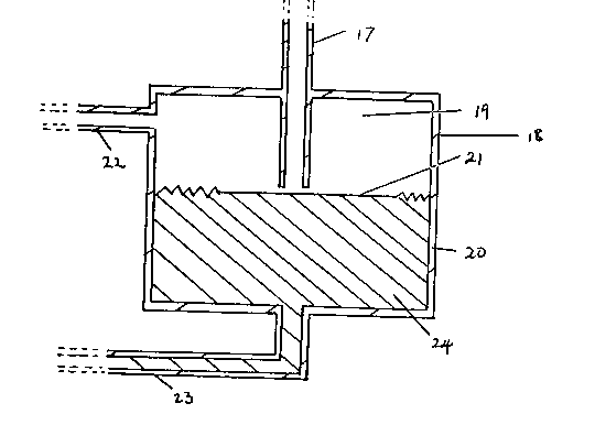
Leading from the cathode compartment 4 of the
electrolytic cell 1 is a pipe 17 through which gaseous
product of electrolysis may be removed from the cathode
compartment 4. Pipe 17 passes into a vessel 18 which
forms a part of the differential gas pressure control
device. The vessel 18 is divided into an upper section
19 and a lower section 20 by a non-porous and flexible
membrane 21. The membrane 21 is made of a plastic
composite material. A pipe 22 leads from the upper part
19 of the vessel 18 and through pipe 22 gaseous product
of electrolysis from the cathode compartment 4 is passed
to a storage vessel (not shown).
The elevations of the vessels 12 and 18 may be
ad~usted relatlve to each other in order to control the
desired differential gas pressure.
The differential gas pressure control device also
comprises a pipe 23 which connects the lower part 14 of
vessel 12 with the lower part 20 of vessel 18, and the
pipe 23 is filled with a hydraulic liquid 24.
In operation of the differential gas pressure
control device shown in Figures 1 and 2 gaseous product
from the anode compartment 2 of the electrolytic cell 1
passes via pipe 11 into the upper part 13 of vessel 12
and then out of vessel 12 via pipe 16 to a storage vessel
(not shown). Similarly, gaseous product from the cathode
compartment 4 of the electrolytlc cell 1 passes via pipe
17 into the upper part 19 of vessel 18 and then out of
vessel 18 via plpe 22 to a storage vessel (not shown).
When the differential gas pressure between the gaseous
products from the anode and cathode compartments is less
than the desired value the excess pressure of the gaseous
product from the cathode compartment 4 acts on the
~8~3025
- 15 -
flexible membrane 21 in vessel 18 and depresses the
flexible membrane resulting in an increase in the flow of
cathode gas from pipe 17 and a decrease in the pressure
of the cathode gas in cathode compartment 4. The
movement of flexible membrane 21 is transmitted via
hydraulic li~uid 23 to flexible membrane 15 in vessel 12
which is caused to rise. Movement of flexible membrane
lS restricts the flow of gaseous product of electrolysis
from the anode compartment 2 out of pipe 11 thereby
leading to a decrease in the flow of anode gas and an
increase in pressure of the anode gas in the anode
compartment 2. The desired differential gas pressure is
thus restored.
Similarly, when the differential pressure between
the gaseous products from the anode and cathode
compartments is greater than the desired value the
excess pressure of the gaseous product from the anode
compartment 2 acts on the flexible membrane 15 in vessel
12 and depresses the membrane resulting in an increase in
the flow of the anode gas from pipe 11 and a decrease in
the pressure of anode gas in the anode compartment 2. The
movement of the flexible membrane 15 is transmitted via
hydraulic liguid 23 to flexible membrane 21 in vessel 18
which is caused to rise. Movement of membrane 21
restricts the flow of gaseous product of electrolysis
from the cathode compartment 4 out of pipe 17 thereby
leading to a decrease in the flow of cathode gas and an
increase in pressure of the cathode gas in the cathode
compartment 4 and to a restoration of the desired value
of the differential gas pressure.
The differential pressure control device shown in
Figures 3 and 4 is made of two sheets 30, 31 of organic
plastics material. The sheet 31 comprises an orifice 32
and a channel 33 leading to a central passage 34. The
sheet 31 also has a channel 35 which leads from the
~2~3~025
- 16 -
central passage 34 and to a channel 36 and orifice 37 in
sheet 30. The sheet 31 comprises an orifice 38 and a
channel 39 which leads to a channel 40 in sheet 30.
Channel 40 leads to a central passsage 41. The sheet 30
also has a channel 42 which leads from the central
passage 41 to an orifice 43. The central passage 34 is
separated from the central passage 41 by a flexible non-
porous rubber membrane 44.
The differential gas pressure control device is
particularly suitable for use with a filter press type
electrolytic cell and in use it may be attached at an end
of such a cell with the orifice 32 attached so as to
receive gaseous product of electrolysis from the anode
compartments of the cell and orifice 38 attached so as to
receive gaseous product from the cathode compartments of
the cell. In operation gaseous product from the anode
compartments of the cell passes lnto the device through
orifice 32, along channel 33 and central passage 34, and
thence along channels 35 and 36 and out of the device at
orifice 37 to a storage vessel (not shown). Gaseous
product from the cathode compartments of the cell passes
into the device through orifice 38, along channels 39 and
- 40 and central passage 41, and thence along channel 42
and out of the device at orifice 43 to a storage vessel
(not shown).
When the differential pressure between the gaseous
products from the anode and cathode compartments of the
electrolytic cell is less than the desired value the
excess presssure of the gaseous product from the cathode
compartments acts on the flexible membrane 44 in such a
way as to move it into centrol passage 34 and restrict
the flow of gaseous product from the anode compartments
through central passage 34. Restriction of the flow of
gaseous product in central passage 34 causes the pressure
of the gaseous product in the anode compartments of the
02S
electrolytic cell to increase thus restoring the
differential gas pressure to the desired value.
Similarly, when the differential pressure between
the gaseous products from the anode and cathode
compartments of the electrolytic cells is greater than
the desired value the excess pressure of the gaseous
product from the anode compartments acts on the flexible
membrane 44 in such a way as to move it into central
passage 41 and restrict the flow of gaseous product from
the anode compartments through central passage 41.
Restriction of the flow of gaseous product in central
passage 41 causes the pressure of the gaseous product in
the cathode compartments to increase thus restoring the
differential gas pressure to the desired value.