Note: Descriptions are shown in the official language in which they were submitted.
`. 1~88125
ROTATING ELECTRIC MACHINE WITH EXTERNAL ROTOR
The present invention relates to a rotating electric
machine with external rotor, and more particularly to an
electric motor with external rotor cage, with an improved
mechanical structure.
Rotating electric machihes with external rotor, and in
particular asynchronous electric motors with external cage
rotor, are known. The purposes of this constructive solution
are well known and dictated by the requirements of the
particular applications (such as,in particular, axial and
centrifugal fans mounted directly on the rotor frame, devices
which require a high inertia of the rotating masses and an
enhancement of the self-ventilating effect, etc.).
A typical known form of construction of such a mol:or
with external rotor, given by way of comparison in figure 1,
which will be commented in greater detail hereinafter,
comprises a supporting axial element constituted by a flanged
bush which is protrudingly mounted on a stationary supporting
shield, and externally supports the active stator parts and
in its interior a coaxial shaft, mounted rotatable on
bearings also internal to the bush, and with a shaft end
protruding from said bush. On the shaft end which protrudes
from the bush there is keyed the opposite shield,
12~312~
-- 2
protrudingly and monclithically supporting the rotor frame and
: the related active parts contained therein ("rotor cage" and
lamellar core).
Such a construction of the prior art has several
disadvantages among which:
- difficult centering and critical plays of the rotating
masses, due to the protruding mounting of the external rotor part
on the shaft end protruding from the bush;
- high stress and wear of the bearings, consequent to the
protruding mounting of the rotating structure and to the
concentricity errors deriving therefrom, with the aggravation
that the need to contain the bearings inside the bush limits
their size, and forces their operation in a hot enrivonment and
in an axially close mutual position;
- noise, due to the above reasons;
- need for forced mounting of the stator pack on the bush,
with consequent deformation of the bearing seats;
- oversizing of the diameter of the bush, which must
contain the shaft at the expense of the active stator material;
- plurality of parts, and of mechanical machinings of the
related coupling surfaces.
The aim of the present invention is to eliminate the above
described disadvantages of the prior art.
According to one aspect of the invention, there is provided
a rotating electrical machine comprising a stationary support
shield, a stationary axial supporting element in the form of a
tubular sleeve monolithically integral with the stationary
support shield, the stationary axial supporting element having a
.- ~
~2~ 5
cylindrical outer surface and the stationary axial supporting
element being provided with an axial hole communicating with an
outer side of the machine through an opening in the stationary
support shield. The stationary support shield is further provided
with a radial hole communicating with the axial hole and with an
outer side of the stationary axial supporting element. Active
stator parts are mounted externally to the stationary axial
supporting element and a rotor structure is rotatably mounted to
the stationary axial supporting element to revolve externally and
coaxially to the stator parts. The rotor structure comprises an
active rotor part and support means including at least two rotor
shields for supporting the active rotor part. A pair of bearings
are disposed at opposite ends of the stationary axial supporting
element to rotatably support the rotor shields on the stationary
axial supporting element.
Advantageously, the stationary axial supporting element is
a tubular sleeve obtained by casting monolithically with the
stationary supporting shield.
The structure according to the invention allows the
following advantages:
1. Solid construction, which ensures a greater centering
and squaring of the machine, allowing to eliminate the noise due
to the protruding rotor construction of the prior art;
2. Possibility of adopting greatly oversized bearings with
normal play which allow a longer life, positioned in non-hot
regions and axially well spaced;
3. Reduction of dimensions of the structural parts in
favour of the active stator parts;
~.
~ 2B81;2~
-- 4
4. Significant reduction of the concentricity errors and
therefore further reduction in noise, by virtue of the
possibility of performing a single-step mechanical machining
of the bearing seats, of the stator pack seat and of the
coupling abutment;
5. Possibility of easily reaching,the IP 55 protection
degree according to the IEC norms, with the addition of a
small gasket ring.
Appropriately, the stator pack is blocked on the
stationary axial supporting element by a spline or key type
coupling. This is facilitated by the greater radial
dimensions of the crown of the stator active iron with
respect to the structure according to the prior art, and
allows to eliminate the deformation of the bearing seats due,
in the embodiment according to the prior art, to the forced
keying of the pack on the bush constituting the axial
supporting element.
Other advantages and peculiarities of the present
invention will become apparent from the following detailed
description of a preferred embodiment thereof, with reference
to the accompanying drawings, wherein:
figure 1 is an axial sectional view of the typical
structure of an external-rotor motor according to the prior
art;
figure 2 is an axial sectional view of an example of
structure of rotating electric machine with external rotor
constituted by an asynchronous motor with external cage
rotor, according to the present invention;
~.281~
figure 3 is an axial sectional view of a structure
similar to that of figure 2, in fully enclosed version
corresponding to the IP 55 protection degree according to IEC
norms.
Figure 1 is an axial sectional view of an example of
typical constructive form of an asynchronous motor with
external cage rotor according to the prior art. It mainly
comprises a stationary axial supporting element or bush 1,
substantially cylindrical, having an end insertingly coupled
and fixed with screws 2 to a stationary supporting shield 3;
active stator parts, in turn comprising a stator pack of
lamellar magnetic material 4 coupled by forcing on the outer
surface of the bush 1 and a field winding, of which only the
heads 5 protruding from the recesses of the pack 4 are
visible; and a rotor structure, generally indicated at 6 and
constituted by a lamellar pack of magnetic material 7
included in an aluminum die-casting which embraces like an
external frame 8 the pack, fills its recesses forming the
rotor bars therein (not visible in the sectional plane shown)
and also forms the heads 8a, 8b rigidly associated with the
bars and monolithic therewith, with function both of short-
circuiting rings of the cage and of rotor pack containment
flanges. In the example shown, the flange 8a has a perforated
radial extension 13 to which it is possible to fix directly,
for example, the blades of a fan, not shown. On the side of
the field winding opposite to the connections 9 the same
aluminum die-casting forms a shield 8c, monolithically with
said parts 8, 8a, 8b. The shield 8c is rigidly coupled to an
~ 288125
-- 6
end of a pivot 10 rotatably supported by means of ball
bearings 11, 12 inside the stationary bush 1 and coaxially
thereto.
The above described rotor structure 6, exemplifying the
prior art, is therefore protrudingly supported by means of
the shield 8c on the pivot 10, rotatable within the bush
with the interposition of the bearings 11, 12 internal to
said bush.
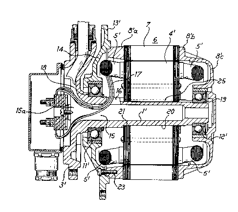
With reference to figure 2, a preferred embodiment of
the rotating electric machine with external rotor according
to the present invention is ~now described, by way of non-
limitative example, constituted by an~asynchronous motor with
external cage rotor. The parts having a function equal or
similar to those of the structure according to the prior art
lS shown in figure 1 are indicated in figure 2 with a same
numeral accompanied by an index ('). In the following
description, only the differences of the structure according
to the present invention from that according to the prior art
of figure 1 will be pointed out.
The rotor structure 6' (figure 2) comprises two shields
(14, 8'c) for supporting the active rotor parts, and
supported by means of bearings, respectively 11' and 12', at
the two ends of the outer surface of a stationary axial
supporting element or sleeve 1. The sleeve 1 has an axial
hole 15 communicating with the outer terminal board 18
through an opening of the supporting shield 3' and a radial
hole 16 for the exit of the electric connections 17 of the
field winding S'.
~.288125
In this structure according to the present invention the
rotor part 6', differently from the solution according to the
prior art, rests at both ends on the axial supporting
element, or sleeve 1, instead of protrudingly, with the
already mentioned advantages of greater solidity and
centering. Furthermore the bearings 11', 12', being external
to the axial supporting element 1, may be oversized and have
normal play, with the also already mentioned advantages of
greater solidity and durability.
For the same reason, the sleeve 1' can have a diameter
smaller than that of the prior art supporting element
(figure 1), leaving greater room for the active material of
the stator pack 4', with consequent improvement of the
electric performance of the motor. Ample room is also left to
interleave coupling elements between the sleeve 1 and the
stator pack 4', for example of the type with key or tab and
related seat, so as to avoid a keying obtained exclusively by
forcing, as used in the prior art and source of deformation
of the bearing seats.
In the embodiment shown, the sleeve 1' is made by
monolithic casting with the stationary supporting shield 3'.
This allows a single-step mechanical machining of the bearing
seats 18, 19, of the seat of the stator pack 20 and of the
coupling abutment 21. This, besides reducing machining times,
allows more strict tolerances, with enhancement of the above
described advantages of centering etc. Furthermore, a single
part 1' replaces four ones of the prior art construction of
figure 1 (supporting shield 3, axial supporting element 1,
1288125
pivot 10 and centering bush 22).
In the example of embodiment of figure 2, the
connections-side rotor shield 14 is separable from the rotor
structure 6' and connected thereto by means of an insertion
coupling and of screws 23, for ease in assembly.
A further advantage of the construction according to the
present invention is to easily allow the obtainment, in a
rotating electric machine with external rotor of the type
described, of an IP 55 protection degree according to IEC
norms, corresponding to a fully enclosed construction. With
reference to figure 2, this is obtainable by means of the
simple addition of an elastomer gasket ring 24 in front of
the connections-side bearing, between the rotor shield 14 and
the stationary supporting shield 3'. The same figure also
shows a variated aspect of the locking system with key and
key-seat between the stator pack and the sleeve 1.
As is evident to the expert, many modifications and
variations can be performed to the construction according to
the embodiment described herein, without abandoning the scope
of the present invention. Furthermore, the invention is not
limited to the application to cage-type asynchronous motor
shown herein. It is in fact evident that the rotor with
squirrel-cage shorted winding represented herein may be
replaced with a wound rotor, the winding whereof leads to a
slip ring arranged externally on the rotor part, for example
to a frontal slip ring applied to the outer rotating shield.
Furthermore, the construction according to the present
invention is applicable to a synchronous machine, for example
~.~88~25
g
with rotating external inductor with permanent magnets, or
with a field winding connected to a slip ring as described
above, or even to a direct-current machine, with obvious
modifications.