Note: Descriptions are shown in the official language in which they were submitted.
E~CKGROUND OF TIIE: INVENTION
Field of the Invention
_
This appl;cation is a division of application
Serial No. 494,371 filed October 31, 1985.
This invention relates to a procedure for preparing a
patient prior to the admini tration of medlcal treatment. The
~vent~n re~ates more particularly to an tmproved apparatu~ an~
method which facllitate~ the preparation procedure.
Description of the Pr~or Ar~
Prior to medical treatment such a~ surgery, suturing,
treatment of super~ic~a~ wounds and fracture~, etc., it ~8 gener-
ally necessary to prepare tha patient' 9 body site at which the
treatment will be administered. The preparation procedure com-
prlses the removal of body hair, clean3ing and s~erllzlng the
body site. ~ody hair 18 removed to facilitatQ acces~, viewlng
and th~ appl~cation of various medlcants. In some hospital~Q,
the preparation procedure may be required with different patlents
as often as forty to Qixty time~ each day, depending upon the
day-to-day demands on the surgical department. The preparation
procedure i~ also frequently required at more limited emergency
medical facilities and at phyGicians' office~. Prefera~ly, the
procedure is conducted with ~ degree of cleanliness and sterility
aommensurate with the requ~rements of the medical treatment to
~Q performed.
In a prior hair removal preparation procedura, body
hair was removed by moisten~ng or lathering the body site and
shavl~g with a saety razor~ Cleanllness and sterillty of tl~e
ha~r rPmo~ p~ooedure w~re obta~n2d .tn lar~q mea~ure ~y the
~s~ o~ ~ ~ter~liz~d, di~p~sabl~ bla~ h~ ~ad~ wa~ d~scard~d
. . - .
~ r one use~ Subsequently, the advent of an economical,
disposable,safety razor made it feasible to employ the razor
a si~gle time and to discard the razor after one use.
It has b~en determined by medical practitioners that
although a safety razor shaves the body site substantially clean
of all body hair, ~having is not necessary to satisfy the needs
of the medical procedure. Rather, a simple removal of relatively
longer hairs, e.g. greater than one sixteenth to one eighth inch
in.length, is sufficient to provide the desired access and viewing.
Moreover, the use of the safety razor in the preparation procedure
has frequent~y caused small nicks and cuts in the skin at the body
site. These wounds at times resulted in post-treatment infection.
These two factors have led to the discontinuance, in part, of the
use of a safety razor, and, the use instead of a hand held clipper.
While the clipper does not crop as closely as the straight-edge
razor, it does adequately remove hair and importantly avoids the
introduction of skin wounds which are later susceptible to
infection. However, in view of the greater cost of a clipper
relative to a disposable safety razor, discarding the clipper-after
20 each use would render the procedure prohibitively expensive and the
clipper is reused. The time involved in sterilizing a clipper
combined with the demand for frequent and repeated use, as in a
hospital facility, has necessitated that a relatively large number
of sterilized clippers be provided. This requirement undesirably
increases the overall cost of the hair removal procedure.
Moreover, while the problem of post-treatment infection is overcome
by the use of a clipper, the operation and manipulation of a hand-
held, manually operated, hair clipper during the preparation
procedure is at times difficult, particularly at body sites which
30 are not readily accessible.
- 2 -
'3.~
S MM~RY OF T~IE INVENTION
The invention consists of an improved method for
the preparation of a body site by the removal of body hair
from the site prior to the application of medical treatment
at the site, comprising: a. mounting a sterile, cutter-head
to a hand-held, electrically-energized, hair-clipper
apparatus; b. advancing the apparatus to a body site at
which medical treatment is to be applied; c. manipulating
the cutter-head ~or the removal of body hair from the site;
and d. removing the cutter-head from the hair-clipper
apparatus and discarding the cutter-head after one use.
'3
BRIEP DESCRIPTION OF TIIE DRAWINGS
___ _~_ _ _
These and other objects and ~ea~ures o~ the Lnvention
will become apparent with reference to the following
specification and to the drawings wherein:
FIGURE 1 is a side elevation view of an embodiment of
the hair clipper apparatus of this invention;
FIGURE 2 is an enlarged, fragmentary, sectional view,
partly broken away of the cutter head and housing of
Figure 1,
FIGURE 3 is an enlarged, fragmentary view, partly
broken away, taken along line 3-3 of Figure 2;
FIGURE 4 is an enlarged, fragmentary view, partly
broken away, taken along line 4-4 of Figure 2;
FIGURE 5 is an enlarged plan view, partly broken away
and partly in section, of the hair clipper apparatus of
: Figure l;
FIGURE 6 is a frag~nentary view taken along line 6-6 of
Figure 5;
FIGURE 7 is a fragmentary view of an alternative
embodiment of a cutter head assembly of Figure 2;
FIGURE 8 is a fragmentary view of the hair clipper of
Figure 1 illustrating disassembly of the cutter head from
the housing of the apparatus;
FIGURE 9 is an enlarged, perspective, fragmentary,
partly exploded view of the cutter head of Figure l;
FIGUR~ 10 is an enlarged, fragmentary, perspective
view of a base member of the cutter head assembly of
Figure 7;
FIGURE 11 is an enlarged, fragmentary plan view of a
stationary cutter member of the cutter head of Figure 9;
and
FIGURE 12 is an enlarged, fragmentary view of the
cutters of Figure 7.
DETAIL~D DESCRIPTION
. _ _ _ _ _
~ eferring no~ to the ~rawing~, a hair-clipper
apparatus indicated generally by reference numeral 12 is
shown to have a housing body with an elongated, curved
handle segment 14, a shoulder segment 16 and an elongated
neck segment 18. A cutter head 20 is demountably mounted
to the neck segment 18, as described moee fully herein-
after. This handle, shoulder, neck and cutter head
arrangement facilitates placement and manipulation of the
cutter head 20 at a body site from which body hair is to
be removed prior to a medical procedure. The housing is
preferably formed of a polymer plastic such as a high-
impact, styrene-type, rigid, thermoplastic resin material.
One such material is commonly available and is sold under
thè name CYCOLAC.* ~ -
An electrically energized means for actuating the
cutter head 20 is provided and comprises an electric motor
22 positioned and supported in the housing handle segment
14. A source of alternating electrical energy, not shown,
for energizing the motor 20 is coupled to the handle
segment 14. Alternatively, a rechargeable electric storage
means may be mounted in the handle segment. These means
for energizing the motor 22 are well known in the art.
A drive coupling means for coupling an actuating force
to the cutter head 20 from the motor 22 is provided. The
drive coupling means includes a reciprocating drive member
24 which is connected to an armature of the motor 22 and
reciprocates therewith. This arrangement of electric motor
22 and reciprocating drive member 24 is well known in the
art. One feature of this invention is the provision of an
oscillator 26 which, as best seen in Figures 2 and 3,
extends from the shoulder segment 16, through the neck
*Trade Mark
3~ 3'3
segment 18 and to the cutter head 20. The oscillat~r
member 26 includes a hub segment 2~ in which a bore 30 is
formed and througll which an osclllator sha~t 32 extends.
The oscillator shaft 32 is supported in bores 34 and 38 of
the neck segment 18. A spring member 42 is positioned
about the shaft 32 for establishing a spring force on the
member 26 and inhibits end play in the oscillating member
26 on shaft 32. Oscillator member 26 further includes a
bifurcated segment having legs 44 and 46 which extend
toward, and, engage the reciprocating drive member 24.
The oscillating member 26 is formed of a polymer plastic,
as for example DELRIN, which is available from the DuPont
Corpoeation. Each of the bifurcated leg segments 44 and
46 includes integrally formed segments 48 and 49,
respectively, which extend laterally toward each other and
which resillently engage the drive member 24. Resilient
engagement is provided both by fabricating the member 26
; of a material which provides some limited yield in the
bifurcated configuration and by spacing distal parts 50
and 51, respectively, of the segments 48 and 49 a distance
for causing slight deflection of the bifurcated leg
segments when the drive member 24 extends between these
segments and is positioned in engagement with the
oscillator member 26. The oscillating member 26 further
includes at an opposite end thereof a generally spherically
shaped segment 52, which enga~es a cutter drive member 54.
The drive member 54 includes integrally formed spaced apart
wall segments 56 and 58 between which the spherical segment
52 extends. In operation, as the motor 22 is energi~ed,
the drive member 24 will oscillate with a reciprocating
motion in the direction indicated by the line and arrows 59
in Figure 6. This reciprocating motion is transmitted by
*Trade Mark
_ 6 _
the oscillator member 26 to the cutter drive member 54
causing this member to reciprocate. Member 54 is also
~ormed of DEL~IN.
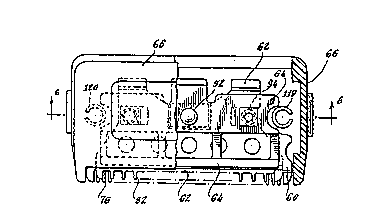
As best seen in the exploded vlew of Figure 9, the
disposable cutter head 20 comprises an assembly of a first
stationary cutter member 60, the drive member 54, a second
movable cutter member 62, a resilient member 64, a cover
member 66 and a base member 68. The first stationary
cutter member 60 comprises an elongated, metal body having
a plurality of cutter teeth 76 formed along its length at
one edge thereof. An aperture 78 is centrally formed in
member 60 and the drive member 54 extends therethrough.
The dimensions of the aperture 78 are selected to permit
reciprocating motion of the drive member 54 within the
aperture in the direction indicated by the arrows 80 in
Figure 9.
~he movable cutter member 62 is similarly an elongated,
metal body having a plurality of cutter teeth 82 formed
along its length at one edge thereof. These teeth and the
teeth of the stationary cutter member are configured to
reduce nicking as is described more fully hereinafter.
Apertures 84 and 86 are formed in the body 62 for receiving
studs 88 and 90, respectively, of the drive member 54.
After these studs are placed in the apertures, they are set
by mechanical, heat or ultrasonic staking so that the drive
member body 54 is rigidly connected to the cutter member 62.
The resilient body 64 is formed of a spring metal and
includes a depending tab segment 92. When the cutter head
20 is assembled, the teeth 82 of the movable cutter member
62 will be juxtaposed with respect to the teeth 76 of the
cutter member 60. The resilient body 64 operates to
establish a force on the movable cutter m~mber 62 for
~aintaining these teeth in sliding engagement with the teeth 76 of
the stationary cutter member during operation.
The stationary cutter 60, the movable cutter 62 with the drive
member 54 mounted thereto, the resilient body 64 and the cover
member 66 are formed into an assembly. Cover member 66 comprises
an elongated body having a generally planar configuration and an
external exposed surface and is formed of a polymer plastic, such
as CYCOLAC Bosses 94 and 96 (Figure 6), which are integrally formed
with the cover member 66, depend from a lower surface thereof.
These bosses extend respectively through apertures 98 and lOO of
the resilient body 64 ~Figu_e 9), through slots 102 and 104 of the
movable cutter member 62 and through apertures 106 and 108 of the
stationary cutter member 60. The bosses are then set by
mechanical, heat or ultrasonic staking to maintain these members
in alignment and mounted to the head 66.
The base member 68 comprises an elongated body having a
generally planar configuration and an external exposed surface and
is formed of a polymer plastic, such as CYCOLAC, and 20 includes
a plurality of comb teeth 110 extending along its length at an edge
thereof. These teeth serve to guide hair, which is to be cut, to
the cutter teeth of the stationary and movable cutters 60 and 62.
An aperture 112 is formed in this body for enabling extension of
the drive member 54 therethrough. The base member 68 is assembled
to the head cover member 66 with studs 114 and 116 which extend
from the surface of the base member. These studs are located at
opposite ends of the base member and extend into bores formed in
bosses 118 and 120 which are integrally formed with and depend from
the surface of the head member 66. The stu~s are secured to the
bosses by any suitable means such as with ultrasonic welding,
heat staking, adhesives, etc. The stationary cutter member
~
~0 and the spring member G4 include notches 123 and 127,
respectively, for provlding clearance ~or these studs.
The cover and base members 66 and 68 respectively form an
enclosure for the cutter head 20.
A means for demountably mounting the cutter head 20 to
the neck segment 18 is provided. This mounting means
comprises clip segments 123 and 127 which are integ~ally
formed with the base member 68, a lower surface 125 of the
base member 68, and collar segments 126 and 128 which are
integrally formed with the neck segment 18. The clip
segments 122 and 124, which are also shown fragmented in
Figure 9 for clarity, extend laterally in the direction of
width of the base body 68 and depend from the body by a
distance determined by the slanted depending segments 130
and 132. This distance is selected for providing a snug
fit between the lower surface 125 of the base body 68 and
the clips 1~2 and 124 as they are advanced into engagement
with lower surfaces 134 and 136 of the shoulder segments
126 and 128, respectively. As will be appreciated, the
fully assembled cutter head 20 is mounted by advancing it
in a lateral direction as illustrated in Figure 8, and
sliding the clips 123 and 127 under the shoulders 126 and
128. The clips will advance and provide captivation of
the cutter head 20 on the neck segment 18. Each of the
clips 123 and 127 includes a tapered segment 138 and 140
which facilitates slight deflection and location of the
clips adjacent to the lower surfaces 134 and 136. A
detenting means is provided which comprises semispherical
shaped risers 142 and 144 extending upwardly from the clips
122 and 124, respectively and which engage corresponding
recesses 146 and 148 formed in lower surfaces 134 and 136,
respectively, As the cutter head 20 is advanced into
engagement with the neck 18, as described, the wall
segments 56 and 58 of the drive member 54 which depend from
3~
the cutter head assembly 20 will straddle the spher~cal
segment 52 of the oscillator member 26 and will be engaged
therewith.
The stationaey cutter teeth in accordance w$th one
feature of the invention are configured for reducing the
possibility of nicking the patlent's skin during the
medical preparation procedure. This is accomplished by
f~rming the stationary cutter teeth 76, as illustrated in
Figures 11 and 12, with corner segments which are
curvilinear rather than squared off. In Figure 11, the
corners illustrated by the dashed lines 149 are eliminated
and curvilinear segments 150 are provided. These
curvilinear segments eliminate edges which can possibly
contact, engage and nick the skin during the preparation
procedure. The movable cutter teeth are similarly
configured. Forming the curvilinear segments can be
conveniently accomplished by a tooth piercing operation
during which the teeth and curvilinear segments are formed
simultaneously.
- 20 In addition, the teeth 76 of the stationary cutter 60
include at their distal locations a flanged segment 153.
This flanged segment extends away from the general plane
of the cutter members and operates to deflect rather than
to engage skin which the cutter teeth 76 might contact.
8y extending this flanged segment beyond the distal edges
of the movable cutter teeth 82 as shown, and by similarly
rounding the cutter teeth 82, the teeth as thus confi-
- 10; -
gured sub~tantlally reduce contac~, engagement and n~ ck~ng of ~hesk~n.
The contour of the shoulder 16, the neck 18 and the cutter
head 20 are conf~gured for facilitatlng ready placement and man~pu-
lation of the cutter head at the ~ite to be trimmed and do ~o
without obstructlng vi~bility of the user. It-will be observed
from the drawings that the neck segment 18 and the cutter head 20
have a bird like configuration with an extending beak. The cutter-
teeth are dispo~ed forwardly near the edqe of the beak and the
~ize of the apparatus body itself around the cutter teeth 18 ub-
~tantially reduced by virtue of the configuration of the neck and
the shoulder and the low profile of the cutter head. Subst~ntial
vi~ibility and facility for manipulating the cutter teeth at the
~ite is thus provided.
The apparatus described car. advanta~eously be u~ed *ith eithe~
an advancing, pu~hlng motion, l.e., advanced away from the user or
with a rearward drawing motion, i.e., drawn toward the u~er. Comb
teeth 110 of the base member 68 enhance the pushing motion by gui-
dlng hair to the cutters. If the apparatus i9 to be us~d ln a rea~-
ward drawing motlon, l.ë.~ toward ~he user rather than used in anadvancing pushing motion, the teeth 110 of the base member 68 can
be deleted as illustrated in the embodiment of Figures ? and 13.
An improved hair clipper apparatu~ for use in preparing a
body site prior to a medi!cal procedure ha~ thu~ been de~cribe~.
The apparatus i9 advantageou~ in that the cutter head i~ readily
placed and demounted from the apparatu~. The cutter head assembly
utilizes a relatively limited ~umber of comoonents which are a3semt
b~ed ln ~ relatlvely ~imple ~n~ no~jaomplex manner. Th~s ~ubst~n
tially reduce~ the co~t of the cutter head and renders it economl-
cally disposable after each u~e. It is thu~ particularly appli-
cable and useful in medical preparation procedures where ~terile
cleanlines~ 19 paramount. The cutter head arrangement further
feature~ cutter teeth configured to substantially avoid the pos~i-
- -- 11 --
bility of contacting, engaglng and nicking body skin during a
preparation procedure. An improved oscillator memher has also
been disclosed which provides a resllient grip on a drive member
and is readily mounted to the apparatus. The hair clipper appara-
tus described is particularlv useful in medical preparation pro-
cedures whère it i~ desirable to avoid infection resulting from
nicking the skin and to be able to dispose of the cutter head
after each use. The appar~tus i~ further advantageous in that it
can be used in trimming hair both with a forward pushing stroke or
with a rearward drawing stroke.
While we have described particular embodiments of our inven-
tion, it will be apparent to those skilled in the art that varia-
tion~ may be made thereto without departing from the spirit of the
invention and the scope of the appended claim~.