Language selection

Search

Patent 1288676 Summary

Third-party information liability

Some of the information on this Web page has been provided by external sources. The Government of Canada is not responsible for the accuracy, reliability or currency of the information supplied by external sources. Users wishing to rely upon this information should consult directly with the source of the information. Content provided by external sources is not subject to official languages, privacy and accessibility requirements.

Claims and Abstract availability

Any discrepancies in the text and image of the Claims and Abstract are due to differing posting times. Text of the Claims and Abstract are posted:

  • At the time the application is open to public inspection;
  • At the time of issue of the patent (grant).
(12) Patent: (11) CA 1288676
(21) Application Number: 1288676
(54) English Title: ARRANGEMENT FOR SEALING A CHAMBER CONTAINING PRESSURE MEDIUM
(54) French Title: DISPOSITIF DE SCELLEMENT D'UNE CHAMBRE A CONTENU SOUS PRESSION
Status: Expired and beyond the Period of Reversal
Bibliographic Data
(51) International Patent Classification (IPC):
  • F16J 15/16 (2006.01)
  • B27N 3/24 (2006.01)
  • B30B 5/06 (2006.01)
  • D21F 3/02 (2006.01)
  • D21F 5/00 (2006.01)
  • F16J 15/40 (2006.01)
(72) Inventors :
  • RAUTAKORPI, PAAVO (Finland)
  • MAJANIEMI, PEKKA (Finland)
  • LEHTINEN, JUKKA (Finland)
(73) Owners :
  • VALMET CORPORATION
(71) Applicants :
  • VALMET CORPORATION (Finland)
(74) Agent: NORTON ROSE FULBRIGHT CANADA LLP/S.E.N.C.R.L., S.R.L.
(74) Associate agent:
(45) Issued: 1991-09-10
(22) Filed Date: 1987-12-15
Availability of licence: N/A
Dedicated to the Public: N/A
(25) Language of filing: English

Patent Cooperation Treaty (PCT): No

(30) Application Priority Data:
Application No. Country/Territory Date
870569 (Finland) 1987-02-11

Abstracts

English Abstract


Abstract
The invention relates to an arrangement for
sealing a chamber containing pressure medium against a
movable band. The band is arranged to form one side of
the chamber. The arrangement comprises a sealing
framework which is fastened to a body part of the
chamber by means of a resilient membrane. The sealing
framework is further provided with a sealing means for
providing a sealing effect between the movable band
and the rest of the chamber. The sealing means is
thereby arranged to be pressed against the band by the
pressure effect of a load medium fed on one side of
the resilient membrane. In order to obtain an effect-
ive and adaptable sealing effect, the means for pro-
viding the sealing effect is formed by at least two
sealing elements arranged in parallel and between
which a sealing liquid is provided.
(Figure 1)


Claims

Note: Claims are shown in the official language in which they were submitted.

The embodiments of the invention in which an enclu-
sive property or privilege is claimed are defined as
follows:-
1. An arrangement for sealing a chamber containing
pressure medium against a movable band arranged to
form one side of the chamber, comprising a sealing
framework fastened to a body part of the chamber by
means of a resilient membrane, a sealing means being
arranged in said sealing framework for obtaining a
sealing effect between the movable band and the rest
of the chamber, whereby the sealing means is arranged
to be pressed against the band by the pressure effect
of a load medium to be fed on one side of the
resilient membrane, said means for providing a sealing
effect being formed by at least two sealing elements
arranged in parallel and between which a sealing
liquid is provided.
2. An arrangement according to claim 1, wherein
the load of the sealing elements against the band is
arranged to be unequal.
3. An arrangement according to claim 1, wherein
the sealing elements are different in profile.
4. An arrangement according to claim 1, wherein
the sealing elements are made of different materials.
5. An arrangement according to claim 1, wherein
each one of the sealing elements is positioned in a
separate groove, the bottom of which is provided with
a depressurizing groove.
6. An arrangement according to claim 1, wherein
said pressure medium consists of gaseous pressure
medium and the sealing liquid consists of the
condensation liquid of the pressure medium.
- 6 -

7. An arrangement according to claim 6 for sealing
a chamber containing steam, wherein said gaseous
pressure medium consists of steam and the sealing
liquid consists of water.
- 7 -

Description

Note: Descriptions are shown in the official language in which they were submitted.


The invention relates to an arrangement for
sealing a chamber containing pressure medium agains-t a
movable band arranged to form one side of the chamber,
comprising a seal.ing framework fastened to a body part
of the chamber by means of a resilien-t membrane, a
sealing means being arranged in said sealing framework
for obtaining a sealing effect between the movable
band and the rest of the chamber, whereby the sealing
means is arranged to be pressed against the band by
the pressure efEect of a load medium to be fed on one
side of the resilient membrane.
In connection wi-th wood processing industries,
this kind of arrangement is known e.g. from various
earlier patent speciflca-tions. Said known arrange-
men-ts i.nclude -the prevention or limitation of the
discharge of the steam or air pressure applied in the
drying of paper or the like material from the chamber
to the space surrounding the machine.
The solution disclosed in Finnish Patent
Specification 66041 of Tampella may be mentioned as an
example of the prior art. This prior solution
comprises a rigid heavy frame, whereby a great normal
force is created between -the seal and t.he movable
band, which results in a great power demand and in the
generation of plenty of heat. The generation o:E heat
damages the seal and the band. In additlon, this
prior so:Lution has the d.i.sadvantage that the seal has
no adap-tabi:Lity and the steam discharging from the
chamber causes noise problems.
Other examples to be ment:ioned are the
solutions disclosed in German Offen:l.egungsschrift
3 129 206 and European Patent Application 0 126 865.
-~ .'

~28~
These prior solutions are concerned with the manufac-
ture of chipboard.
The disadvantages o~ German Offenlegungs-
schrift 3 129 206 include the lack of adjustability,
de~icien~ adaptability ~o variations in the web
thickness, noise problems caused by the discharge o
steam, and the deficient conveyance of the created
friction heat. The disadvantages of European Patent
Application 0 126 ~65, in turn, include noise problems
caused even by minor steam leakages and difficulties
occurring in the conveyance of the created friction
heat.
A further disadvantage common to all khe three
above prior solutions is the problems caused by steam
when it is discharged into the space around the
machine.
The object of the invention is to provide a
solution by means of which the disadvantages of the
prior art can be eliminated. This is achieved by means
o~ an arrangement according to the invention which is
characterized in that said means for providing a seal-
ing effect is formed by at least two sealing elements
arranged in par~llel and between which a sealing
liquid is provided.
A ma~or advantage of the invention is that the
friction, heat, noise and adaptability can b~
controlled, whereby all the disadvantages o~ the prior
solutions can be eliminated. A further advantage of
the invention is the simple realizakion thereof, so
that the operation is reliable and the manufacturing
and operating costs are low.
In the following the invention will be de-
scribed in more detail by means of a preferred embodi-
ment shown in the attached drawing, whereby
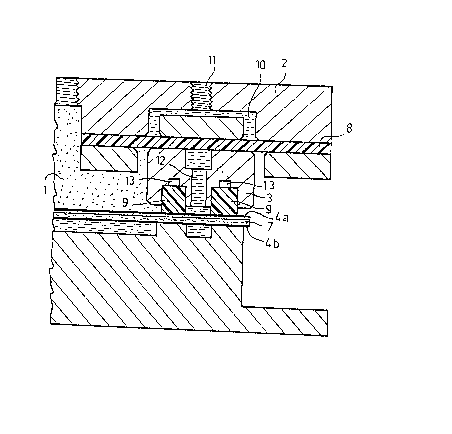
Figure 1 is a general cross-sectional view of
, ' ` ' ' ' ' . '
- : -
'

~2~
an arrangement according to the invention seen in thedirection of movement of the web, and
Figure 2 is a general side view o~ a drying
means for a paper web in which the arrangement of
Figure 1 is used.
In the example of the figures, the reference
numeral 1 indicates a steam chamber. The steam chamber
1 is formed by a body part 2, a sealîng framework 3
which is fastened to the body part and which forms the
edges of the steam chamber 1, and a band 4a movable
with respect to the body part. The band 4a is arranged
to extend as an endless loop around rolls 5a and 5a'.
This arrangement appears clearly from Figure 2.
Below this structure another band 4b is ar-
ranged which is correspondingly arranged to extend
around rolls 5b and 5b' as an endless loop. The loop
formed by the band 4b also appears clearly from
Figure 2.
A weblike product 6, such as a paper web, is
led between the bands 4a, 4b. The paper web 6 is
passed between the bands 4a, 4b on a felt 7. The felt
7 is arranged to rotate as an endless loop as is con-
ventional.
In Figures 1 and 2, the lower portion of the
structure is shown only generally. The structure of
the lower portion may be similar to the structure of
the upper portion shown in the figure. Alternatively,
it is possible to use a water chamber. The arrangement
may thereby be e.g. such as disclosed in Finnish
Pakent Specification 63 078.
The function of the structure shown in the
~igures is to remove water from the web 6 and to
transfer it further away to a suitable place by means
of the felt 7. As to the operation, Finnish Patent
Specifications 66 041 and 63 078 are referred to.
- .
,- ~,
~ .

86~6
~hese matters are comple~ely obvious to one skilled in
the art, so they are not more closely discussed here.
In the example of Figures 1 and 2, the sealing
framework 3 is attached to the hody part I by means of
a resilient membrane 8. In order to seal the gap be-
tween the band 4a rotating around the roll 5a and the
sealing framework 3, two sealing elements 9 arranged
in parallel are provided in the sealing framework 3.
The sealing elements 9 are arranged to be
pressed against the band 4a by the pressure effect of
a pressure medium to be fed into a space 10 defined
between the body part 2 and the membrane 8. The press-
ure medium can be fed into the space 10 through a
conduit 11. The pressure in the space 10 may be ad-
justable.
In addition, a sealing liquid 12 is introduced
between the sealing elements 9 for sealing the gap
between the sealing elements and the band, the
sealing liquid simultaneously acting as a lubricant
and as a cooling agent for the elimination of heat
problems. The sealing elements 9 are positioned in
separate grooves, and in this embodiment the bottoms
of said grooves are provided with depressurizing
grooves 13. The function of the depressurizing
grooves is to reduce the pressure above the saaling
element, so that the pressure prevailing below the
sealing element is sufficient to keep the sealing ele-
ment on the bottom of the groove. Thereby khe press
between the sealing elements and the band can be re-
duced if required, without any risk of the sealing
element being loosened. The press can be reduce,d by
lifting the sealing framework or by reducing the
pressure prevailing in the space 10.
If need be, the load of the sealing elements
against the band 4a can be une~ual. This can be
. .
,.

7~
effected e~g. structurally by the use of pressure com-
pensation. It is likewise possibl0 to use a separate
load mechanis~.
The profiles of the sealing elements 9 may be
eithex similar or dissimilar, and the sealing elements
can be manufactured of the same materia] or different
materials.
The sealing liquid 12 can be any suitable
liquid. When a gaseous pressure medium, such as steam,
is used in the chamber 1, the sealing liquid preer-
ably consists of the condensation liquid of said
pressure medium, e.g. water. The sealing liquid arran-
gement can be effected e.g. by introducing sealing li-
~uid between the sealing elements or alternatively by
removing liquid, i.e. steam condensed from the chamber
1, away from between the sealing elements.
The abo~e example arranged in connection with a
Condebelt dryer is by no means intended to restrict
the invention, but the invention can be modified with-
in the claims in various ways. Accordingly, it is
clear that the arrangement according to the invention
or the parts thereof need not necessarily be exactly
similar to those shown in the figures but other kind
of solutions are possible as well. For example, the
sealing framewor~ can be fastened to the membrane in
any suitable way. Correspondingly, the depressurizing
groo~es may differ from those shown in the figures or
they can differ from each other, so that the load
effect of the sealing elements is dissimilar The
seals can also be shaped or fastened so that no de-
pressurizing grooves are needed. The pressure of the
chamber 1 can be adjusted by means of any adjustable
pressure source. The sealing elements need not,
either, be two in number, but it is possible to use
more sealing elements.
.
- .:

Representative Drawing
A single figure which represents the drawing illustrating the invention.
Administrative Status

2024-08-01:As part of the Next Generation Patents (NGP) transition, the Canadian Patents Database (CPD) now contains a more detailed Event History, which replicates the Event Log of our new back-office solution.

Please note that "Inactive:" events refers to events no longer in use in our new back-office solution.

For a clearer understanding of the status of the application/patent presented on this page, the site Disclaimer , as well as the definitions for Patent , Event History , Maintenance Fee  and Payment History  should be consulted.

Event History

Description Date
Inactive: Reversal of expired status 2012-12-05
Time Limit for Reversal Expired 2008-09-10
Letter Sent 2007-09-10
Inactive: IPC from MCD 2006-03-11
Letter Sent 2001-08-27
Grant by Issuance 1991-09-10

Abandonment History

There is no abandonment history.

Owners on Record

Note: Records showing the ownership history in alphabetical order.

Current Owners on Record
VALMET CORPORATION
Past Owners on Record
JUKKA LEHTINEN
PAAVO RAUTAKORPI
PEKKA MAJANIEMI
Past Owners that do not appear in the "Owners on Record" listing will appear in other documentation within the application.
Documents

To view selected files, please enter reCAPTCHA code :


To view images, click a link in the Document Description column. To download the documents, select one or more checkboxes in the first column and then click the "Download Selected in PDF format (Zip Archive)" or the "Download Selected as Single PDF" button.

List of published and non-published patent-specific documents on the CPD .

If you have any difficulty accessing content, you can call the Client Service Centre at 1-866-997-1936 or send them an e-mail at CIPO Client Service Centre.


Document
Description 
Date
(yyyy-mm-dd) 
Number of pages   Size of Image (KB) 
Cover Page 1993-10-22 1 14
Drawings 1993-10-22 1 34
Abstract 1993-10-22 1 23
Claims 1993-10-22 2 41
Descriptions 1993-10-22 5 204
Representative drawing 2001-07-18 1 21
Maintenance Fee Notice 2007-10-22 1 171
Correspondence 2001-08-27 1 16
Fees 1996-08-12 1 50
Fees 1995-08-09 1 38
Fees 1993-08-11 1 30
Fees 1994-08-08 1 44
Maintenance fee payment 1995-06-28 1 46