Language selection

Search

Patent 1288763 Summary

Third-party information liability

Some of the information on this Web page has been provided by external sources. The Government of Canada is not responsible for the accuracy, reliability or currency of the information supplied by external sources. Users wishing to rely upon this information should consult directly with the source of the information. Content provided by external sources is not subject to official languages, privacy and accessibility requirements.

Claims and Abstract availability

Any discrepancies in the text and image of the Claims and Abstract are due to differing posting times. Text of the Claims and Abstract are posted:

  • At the time the application is open to public inspection;
  • At the time of issue of the patent (grant).
(12) Patent: (11) CA 1288763
(21) Application Number: 542274
(54) English Title: COMPENSATOR FOR EARTH BORING BITS
(54) French Title: COMPENSATEUR POUR OUTIL DE FORAGE
Status: Deemed expired
Bibliographic Data
(52) Canadian Patent Classification (CPC):
  • 255/73
(51) International Patent Classification (IPC):
  • E21B 10/24 (2006.01)
  • F16N 7/30 (2006.01)
(72) Inventors :
  • GALLE, EDWARD M. (United States of America)
  • ZAHRADNIK, ANTON F. (United States of America)
(73) Owners :
  • HUGHES TOOL COMPANY (United States of America)
(71) Applicants :
(74) Agent: GOWLING WLG (CANADA) LLP
(74) Associate agent:
(45) Issued: 1991-09-10
(22) Filed Date: 1987-07-16
Availability of licence: N/A
(25) Language of filing: English

Patent Cooperation Treaty (PCT): No

(30) Application Priority Data:
Application No. Country/Territory Date
927,789 United States of America 1986-11-05

Abstracts

English Abstract


ABSTRACT OF THE DISCLOSURE


In an earth boring bit of the type having a rotatable cone secured to
a bearing shaft, an improved pressure compensating and relief system. A
flexible diaphragm has an enlarge peripheral portion in an o-ring
configuration sealingly secured in a compensator cavity to form a mud
region and a lubricant region. A central portion of the diaphragm has a
perforated and ridged protrusion extending into the mud region to form a
self energizing area, exposed to the mud region, that seals the perforation
when the pressure of the lubricant is less than or substantially equal that of
the mud. A wall at the end of the compensator cavity surrounds the mud
passage and engages an area around the protrusion when the diaphragm is
fully extended by lubricant pressure build-up that exceeds the hydrostatic
pressure. Thus, the resulting pressure differential opens the perforation,
releases lubricant and relieves the build-up of lubricant pressure. However,
the configuration of the protrusion is such as to prevent the entrance of
mud into the lubricant reservoir since the exterior area of the protrusion
exceeds that of the interior area. The differential pressure to open the
perforation is selected to be not less than about fifty psi and the preferred
form of the protrusion is substantially cylindrical, its perforation and
lubricant entrance being beveled. An absence of metal bonded to the
diaphragm helps avoid failures due to stress induce separations and
debonding due to chemical attack. Clearances are used between the
diaphragm and the end of the cavity and the end of the protector cup to
provide self centering with the lubricant and drilling mud passages.


Claims

Note: Claims are shown in the official language in which they were submitted.


CLAIMS:
1. In combination with an earth boring bit having a rotatable cutter
secured to a bearing shaft on a head, an improved pressure compensating
and relief system which comprises:
seal means between the cutter and the bearing shaft;
the head including a lubricant passage extending between the bearing
shaft and a compensator cavity;
the compensator cavity having one end exposed, by means of a mud
passage, to mud in a borehole during drilling;
a flexible diaphragm having a periphery sealingly secured in the
compensator cavity to form a mud region and a lubricant region -- and to
induce upon the lubricant the hydrostatic pressure of the mud in a borehole;
a central portion of the diaphragm having a perforated protrusion
extending into the mud region to form a self energizing configuration
exposed to the mud region that seals the perforation when the pressure of
the lubricant is less than or substantially equal that of the mud;
a wall at the end of the compensator cavity surrounding the mud
passage and engaging an area around the protrusion when the diaphragm is
extended by lubricant pressure build-up that exceeds the mud pressure;
whereby the resulting pressure build-up opens the perforation to
release lubricant.


-10-


2. The invention defined by claim 1 which further comprises an
exclusively rubber diaphragm with an enlarged peripheral portion and a
rigid protector cup biased against and compressing the peripheral portion.

-11-


3. The invention defined by claim 2 wherein the end of the diaphragm
has clearance from the end of the compensator cavity and clearance from
the end of the protector cup when fully extended but unstressed.


-12-


4. In combination with an earth boring bit having a rotatable cutter
secured to a bearing shaft on a head, an improved pressure compensating
and relief system which comprises:
seal means between the cutter and the bearing shaft;
the head including a lubricant passage extending between the bearing
shaft and a compensator cavity;
the compensator cavity having one end exposed, by means of a mud
passage, to mud in a borehole during drilling;
a flexible diaphragm having a periphery sealingly secured in the
compensator cavity to form a mud region and a lubricant region -- and to
induce upon the lubricant the hydrostatic pressure of the mud in a borehole;
a central portion of the diaphragm having a perforated protrusion
extending into the mud region to form a larger area of diaphragm around
the perforation in the mud region than in the lubricant region to create a
self energizing effect that seals the perforation when the pressure of the
lubricant is less than or substantially equal that of the mud;
a wall at the end of the compensator cavity surrounding the mud
passage and engaging an area around the protrusion when the diaphragm is
extended by lubricant pressure build-up that exceeds the hydrostatic
pressure;
whereby the resulting pressure opens the perforation, releases
lubricant and relieves the build-up of lubricant pressure.

-13-


5. The invention defined by claim 4 which further comprises an
exclusively rubber diaphragm with an enlarged peripheral portion and a
rigid protector cup biased against and compressing the peripheral portion.


-14-


6. The invention defined by claim 5 wherein the end of the diaphragm
has clearance from the end of the compensator cavity and clearance from
the end of the protector cup when fully extended but unstressed.


-15-


7. In combination with an earth boring bit having a rotatable cutter
secured to a bearing shaft on a head, an improved pressure compensating
and relief system which comprises:
seal means between the cutter and the bearing shaft;
the head including a lubricant passage extending between the bearing
shaft and a compensator cavity,
the compensator cavity having one end exposed, by means of a mud
passage, to mud in a borehole during drilling;
a flexible diaphragm having a periphery sealingly secured in the
compensator cavity to form a mud region and a lubricant region -- and to
induce upon the lubricant the hydrostatic pressure of the mud in a borehole;
a central portion of the diaphragm having a generally cylindrical,
perforated protrusion extending into the mud region, with a beveled entry
to the perforation exposed to the lubricant region, to form a larger area of
diaphragm around the perforation in the mud region than in the lubricant
region to create a self energizing effect that seals the perforation when the
pressure of the lubricant is less than or substantially equal that of the mud;
a wall at the end of the compensator cavity surrounding the mud
passage and engaging an area around the protrusion when the diaphragm is
extended by lubricant pressure build-up that exceeds the hydrostatic
pressure;
whereby the resulting pressure build-up opens the perforation,
releases lubricant and relieves the build-up of lubricant pressure.

-16-


8. The invention defined by claim 7 which further comprises an
exclusively rubber diaphragm with an enlarged peripheral portion and a
rigid protector cup biased against and compressing the peripheral portion.

-17-


9. The invention defined by claim 8 wherein the end of the diaphragm
has clearance from the end of the compensator cavity and clearance from
the end of the protector cup when fully extended but unstressed.


-18-


10. In combination with an earth boring bit having a rotatable cutter
secured to a bearing shaft on a head, an improved pressure compensating
and relief system which comprises:
seal means between the cutter and the bearing shaft;
the head including a lubricant passage extending between the bearing
shaft and a compensator cavity;
the compensator cavity having one end exposed, to mud in a borehole
during drilling;
a compensator cup sealingly retained in the compensator cavity;
a flexible diaphragm without metal components having an enlarged
periphery sealingly secured and compressed in the compensator cavity by
pressure from the compensator cup to form a mud region and a lubricant
region -- and to induce upon the lubricant the hydrostatic pressure of the
mud in a borehole;
pressure relief means in the flexible diaphragm to prevent the
entrance of mud into the lubricant when the pressure of the lubricant is less
than or substantially equal that of the mud but to expel lubricant upon
lubricant pressure build-up.


-19-


11. The invention defined by claim 10 which further comprises an
exclusively rubber diaphragm and a compensator cap to biase the
compensator cup against the enlarged periphery of the diaphragm.


-20-


12. The invention defined by claim 11 wherein the end of the diaphragm
has clearance from the end of the compensator cavity and clearance from
the end of the protector cup when fully extended but unstressed.


-21-

Description

Note: Descriptions are shown in the official language in which they were submitted.


~,~?d ~38~

3 BAC~GROUND OF T~IE INVENTION

~ 1. Field of the Invention:
6 Th;s invention relates in general to ea}th boring bits but in particular
7 to improvements in their lubricant pressure compensators and relief means.

9 2. Descriptio_of the Prior Art:
Earth boring bits of the roiling cutter type havc sealed bearings and
lubrication systems that include pressure compensation and relief means to
minimize the pressure differential across the seals that separate the
lubricant from the drilling mud in a bore hole.
14 A successful seal means is disclosed by Edward M. Galle in U.S.
Patent No. 3,397,928. A successful pressure compensation and relief means
16 iS disclosed by Stuart C. Millsapps, Jr., in U. S. Patent No. 4,055,225. Other
17 systems include the use of the original commercially successful pressure
18 relief valve disclosed by Galle in U. S. Patent No. 3,476,195 and the use of
19 a pinhole or slit in a flexible compensator or diaphragm that permits liquid
flow either into or from the compensator cavity, as disclosed by Schumacher
21 in U. S. Patent No. 3,847,234.
22 The failure of any element in the lubrication system of a bit
23 eventually, but usually soon, concludes its useful life. Too often~ a life
24 determinative failure occurs in either the diaphragm or the relief means.
~arying stresses caused by the lubricant pressure variations in a bit, along
26 with increased temperatures downhole, accelerate compensator failure,
27 especially those which include metal components bonded to rubber.
28
29
31
32
33
34

7~3


3 SUMMARY OF THE INVENTION

It is the general object of the invention to provide an improved
6 pressure compensating and relief system in an earth boring bit.
7 The improved comensator has a flexible diaphragm in a compensator
8 cavity that minimizes tensile stresses in the diaphragm. Metal components
g are not used in the diaphragm to avoid the failures that occur in the bondcd
o region between metal and rubber.
The flexible diaphragm has a perforated protrusion extending into
2 the dr;lling mud region. The perforation is self energizing and seals when
3 the pressure of the lubricant is less than or substantially equal to that of the
4 mud that surrounds the bit during drilling. A wall at the end of a
compensator cavity in the bit body contains a mud passage and engages an
16 area of the compensator around the protrusion when the diaphragm is fully
17 extended by lubricant pressure build-up that exceeds the hydrostatic
18 pressure of the mud. This minimizes tensile stresses in the diaphragm. The
19 rcsulting pressure differential opens the perforation, releases lubricant and
relieves the build-up of lubricant pressure. This is accomplished in the
21 preferred embodiment by utilizing a protrusion having a larger surface
22 area in the mud region than in the lubricant region. In such an embodiment
23 the exterior or mud side of the protrusion is cylindrical and a be veled
24 entrance to the perforation is used on the lubricant side of the diaphragm.2s The protrusion ideally has an annular reinforcing ridge to confine the ends
26 of the perforation, which is usually a slit. Further, the diaphragm has a
27 periphery enlarged to accomodate an integral o-ring that is compressed
28 between captive, preferably beveled surfaces on a compensator protector cup
29 and the compensator cavity. The end of the diaphragm has clearancc from
the end of the compensator cavity and clearance from the end of the
31 protector cup when fully extended but unstressed. This centers the
32 protrusion when fully extended in either direction.
33
34

.
-3-

3763


3The above as wcll as addit;onal objects, features~ and advantages of the
4invention will become apparent in the following description.


11
. 12
13
14

16
. 17
18
1~
21
22
23
24
26
27
28
2~
31
32
33

-4-
:


3 DESCRIPTION OF THE_DRA~Y_NGS


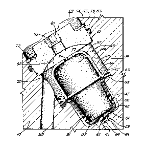
5Figure 1 is a perspective view, partially in longitudinal section, of an
6earth boring bit of the rolling cutter type having a lubricant compensator
7and pressure relief system constructed in aecordance with the principles of
8the invention
gFigure 2 is an enlarged, fragmentary longitudinal section of the
lubricant compensator and pressure relief system shown in Figure 1, showing
11the diaphragm filled with grease.
12Figure 3 is an enlarged, fragmentary longitudinal section, similar to
13that of Figure 2, except the grease in the compensator has been expended
14and drilling mud has essentially filled the compensator.
15Figure 4 is a perspective view of the flexible diaphragm of Figs. 1
16and 2.
17
18
19

21
22
23
2A.
26
26
27
28
29

31
32
33

34

S
,~
.: ..


~ ', ~ ...
'',
'`'```' :

~X~3~il76;~

3 DESCRIPTION OF T~IE PREFl:RRED EMBODTMENT

The numeral 11 in the drawing designates an earth boring bit which
ff consists of three identical head sections 13, each of which supports a
7 rotatable cutter 15 having a plurality of earth disintegrating teeth i7, here
8 depicted as being inserts of sintered tungsten carbide.
g Thus, the three head sections 13 together form a head or body havinga hollow interior 19 which terminates at the lower end in usually three
passages, each containing a nozzle 21 used to direct drilling fluid or mud
12 against the borehole bottom (not shown).
13 A lubricant passage 23 in each head section extends between the
14 bearing means 25 of a cantilevered bearing shaft 26 and a lubricant pressure
compensator and relief means 27.
16 Lubricant is maintained in ~he bearing means 25 by a seal means 29,
17 here an o-ring as shown in the previously mentioned Galle U. S. Patcnt
18 3,397,928. Each rotatable cutter 15 is retained to the bearing shaft 26 by
19 suitable means such as the snap ring, as disclosed by Burr, et al in U.S.
Patent No. 4,491,428.
21 As shown in Fig. 2, a lubricant compensator and relief means 27 is
22 positioned or formed in each of the head sections 13. A mud passage 41
23 leads to an interior body or wall surface 39 (see Fig. I) on the interior of
2~ the bit above the rotatable cutters 15. An interior wall or shoulder 43 forms
the lower part of a compensator cavity 45 which has a lower region 47 of
26 one diameter and an upper region 49 of a larger diameter. A recess 51
27 contains an o-ring 52 in a groove or gland 53 and includes a snap ring 54 in
28 a recess 55 is used to retain a compensator cap 77.
29 The lower region 47 of the compensator cavity 45 as shown in Fig. 2
contains a flexible diaphragm 57 that has a central portion 59 perforated at
31 61 and beveled at 62. The perforation 61 is actually a siit starting in a
32 recess 64 having ends limited by an annular ridge 66. The periphery 63 of
33 the diaphragm 57 is in the form of an o-ring shaped annular area that is

-6-


3 compressed between an inverted incline or lip 65 in the cavity upper region
49 and an opposed downwardly facing beveled portion or shoulder 67 on the
6 lower extremity of a protector cup 69. This cup has an aperture 71 in its
6 upper portion 73j through which grease communicates with the lubricant
7 paSsage 23.
8 The protector cup 69 is biased downwardly by a lower surface 75 in
g a compensator cap 77, which has a passage 79 through which lubricant is
o forced prior to insertion of a pressure seal pipe plug 81. An arcuate groove1l 83 permits lubricant flow freely between the passage 23 in the head section
12 13, around the exterior surface 85 of the protector cup 69, and to or from
13 the interior volume 87 (defined by the interior surfaces 89 of the protector
l-i cup 69 and an interior surface 91 of the flexible diaphragm 57).
Upon assembly and in operation, the flexible diaphragm 57 has its
16 periphery 63 compressed (indicatcd by the dotted lines) and is sealingly
17 secured in the compensator cavity between surfaces 65, 67 to form a mud
18 region 93 and a lubricant volume or region 87. The central portion 59 of
the flexible diaphragm 57 has a perforation 61 and extends into passage 41
of mud region 93 when fully expanded to form a self energizing area,
21 exposed to the drilling mud, that seals the perforation when the pressure of
22 the lubricant is less than or substantially equal to that of the mud.
23 The wall or shoulder 43 at the lower end of the compensator cavity
24 around the mud passage 41 engages the flexible diaphragm when fully
extended by lubricant pressure build-up that exceeds the hydrostatic
26 pressure of the drilling mud. Thus, the resulting pressure differential opcns
27 the perforation 61, releases the lubricant and relieves the build up of
28 lubricant pressure inside the lubricant volume 87.
29 The diaphragm is preferably constructed of nitrile rubber and the
perforation is sized along with the configuration of central portion 59, such
3~ that it will open at a selected pressure not less than substantially fifty psi.
32 This self energizing effect is achieved in the preferrcd embodiment
33 by utilizing a protrusion having an area exposed to the mud that is greater
,~ 34

~ 7 Ei3


3 than the arca exposed to the lubricant such that sealing of the perforation is
4 effected for all mud pressures greater than the lubricant pressurc.
Preferably, the pr~trusion is cylindrical, with a radius joining the extcrior
6 surface of the flexible diaphragm 57, as indicated in Figure 2.
7 The width of perforation or slit 61 is determined by the diamcter of
8 the annular ridge 66. Its length or depth is determined by the thickness of
g the diaphragm, the depth of bevel 62 and the height of central portion or
appendage 59. All of these features determine the differential pressurc at
which ~he slit 61 is energized to release lubricant.
2 Another feature of the invention are the clearances Dl (see Fig. 2)
13 and D2 (see Fig. 3). These clearances occur when the flexible diaphragm is
14 completely filled with lubricant ~Fig. 2) or inverted by drilling mud (Fig. 3),
but before the rubber is stretched. This self-centers the central portion or
6 appendage 59 with respect to mud passage 41 (Fig. 2) and aperture 71 (Fig.
7 3). Otherwise, a relatively thin wall section of the diaphragm may align
8 with either mud passage 41 or aperture 71 and a large pressure differential
may rupture the diaphragm.
It is advantageous that the flexible diaphragm 57 ;s connected
21 without bonding to the compensator cavity 45 by the compression of its
22 periphery 63 between the surface 65 and the beveled portion 67 of the
23 protector cup. Separation and failure of diaphragms or compensators have
24 been observed when metal/rubber bonding is used. Such constructions may
25 cause excessive stress in the rubber at the bonded areas during pressure
26 build-up in the lubricant. Further, the use of a shoulder q3 in the
27 compensator cavity 45 to engage the end of the perforated diaphragm
28 minimizes stresses and enhances reliability. Additionally, the upper portion
73 and the opening 71 of protector cup 69 are designed ~o form a backup
support for the central portion 59 of flexible diaphragm 57 so tha~ when
31 substantially higher mud pressure than lubr;cant pressure exists no damage
32 will occur to the diaphragm.
33
34

-8-

8~


3 While the invention has been described in only one of its forms, it
4 should be apparent to those skilled in the art that it is not so limitcd, but is
susceptible to various changes and modifications without departing from the
6 spirit thereof.


11
12
13
14

16
17
18
19

21
22
23
24


2ff
27
28
29

31
32
33
34

_9_


: .,,' :

. ~

Representative Drawing
A single figure which represents the drawing illustrating the invention.
Administrative Status

For a clearer understanding of the status of the application/patent presented on this page, the site Disclaimer , as well as the definitions for Patent , Administrative Status , Maintenance Fee  and Payment History  should be consulted.

Administrative Status

Title Date
Forecasted Issue Date 1991-09-10
(22) Filed 1987-07-16
(45) Issued 1991-09-10
Deemed Expired 2005-09-12

Abandonment History

There is no abandonment history.

Payment History

Fee Type Anniversary Year Due Date Amount Paid Paid Date
Application Fee $0.00 1987-07-16
Registration of a document - section 124 $0.00 1987-09-28
Registration of a document - section 124 $0.00 1989-03-06
Maintenance Fee - Patent - Old Act 2 1993-09-10 $100.00 1993-08-11
Maintenance Fee - Patent - Old Act 3 1994-09-12 $100.00 1994-08-26
Maintenance Fee - Patent - Old Act 4 1995-09-11 $100.00 1995-08-10
Maintenance Fee - Patent - Old Act 5 1996-09-10 $150.00 1996-08-19
Maintenance Fee - Patent - Old Act 6 1997-09-10 $150.00 1997-08-20
Maintenance Fee - Patent - Old Act 7 1998-09-10 $150.00 1998-08-19
Maintenance Fee - Patent - Old Act 8 1999-09-10 $150.00 1999-08-23
Maintenance Fee - Patent - Old Act 9 2000-09-11 $150.00 2000-08-25
Maintenance Fee - Patent - Old Act 10 2001-09-10 $200.00 2001-08-20
Maintenance Fee - Patent - Old Act 11 2002-09-10 $200.00 2002-08-20
Maintenance Fee - Patent - Old Act 12 2003-09-10 $200.00 2003-08-21
Owners on Record

Note: Records showing the ownership history in alphabetical order.

Current Owners on Record
HUGHES TOOL COMPANY
Past Owners on Record
GALLE, EDWARD M.
HUGHES TOOL COMPANY - USA
ZAHRADNIK, ANTON F.
Past Owners that do not appear in the "Owners on Record" listing will appear in other documentation within the application.
Documents

To view selected files, please enter reCAPTCHA code :


To view images, click a link in the Document Description column. To download the documents, select one or more checkboxes in the first column and then click the "Download Selected in PDF format (Zip Archive)" or the "Download Selected as Single PDF" button.

List of published and non-published patent-specific documents on the CPD .

If you have any difficulty accessing content, you can call the Client Service Centre at 1-866-997-1936 or send them an e-mail at CIPO Client Service Centre.


Document
Description 
Date
(yyyy-mm-dd) 
Number of pages   Size of Image (KB) 
Drawings 1993-10-23 4 228
Claims 1993-10-23 12 197
Abstract 1993-10-23 1 42
Cover Page 1993-10-23 1 15
Description 1993-10-23 8 258
Representative Drawing 2002-01-21 1 37
Fees 1996-08-19 1 30
Fees 1995-08-10 1 33
Fees 1994-08-26 1 36
Fees 1993-08-11 1 14