Language selection

Search

Patent 1288980 Summary

Third-party information liability

Some of the information on this Web page has been provided by external sources. The Government of Canada is not responsible for the accuracy, reliability or currency of the information supplied by external sources. Users wishing to rely upon this information should consult directly with the source of the information. Content provided by external sources is not subject to official languages, privacy and accessibility requirements.

Claims and Abstract availability

Any discrepancies in the text and image of the Claims and Abstract are due to differing posting times. Text of the Claims and Abstract are posted:

  • At the time the application is open to public inspection;
  • At the time of issue of the patent (grant).
(12) Patent: (11) CA 1288980
(21) Application Number: 1288980
(54) English Title: TAPPING SCREW
(54) French Title: VIS AUTOTARAUDEUSE
Status: Expired and beyond the Period of Reversal
Bibliographic Data
(51) International Patent Classification (IPC):
  • F16B 25/00 (2006.01)
  • F16B 25/10 (2006.01)
(72) Inventors :
  • TAKASAKI, SEIICHIRO (Japan)
(73) Owners :
  • YAO SEIBYO CO., LTD.
(71) Applicants :
  • YAO SEIBYO CO., LTD. (Japan)
(74) Agent: SMART & BIGGAR LP
(74) Associate agent:
(45) Issued: 1991-09-17
(22) Filed Date: 1987-07-27
Availability of licence: N/A
Dedicated to the Public: N/A
(25) Language of filing: English

Patent Cooperation Treaty (PCT): No

(30) Application Priority Data:
Application No. Country/Territory Date
62-95054 (Japan) 1987-06-19

Abstracts

English Abstract


ABSTRACT OF THE DISCLOSURE
A tapping screw having a tapered edge at a rear part of
the tapered portion at its tip. The drill edge has the
maximum diameter which is larger than the maximum thread
diameter at the tapered portion and smaller than the maximum
thread diameter at the shank. The drill edge allows the
screw to be driven in more securely with a smaller driving
force.


Claims

Note: Claims are shown in the official language in which they were submitted.

04269-28 GWH:jy
The embodiments of the invention in which an exclusive property
or privilege is claimed are defined as follows.
1. A tapping screw for tapping and screwing into a
substrate comprising:
a shank having a head end, a middle portion, and a tip
end, and said tip end having a tapered portion;
first threads on the outer periphery of said tapered
portion of said tip end for tapping a first thread in
a substrate;
second threads on the outer periphery of said shank at
said head end for tapping a second thread in a
substrate, and separate from said first threads on said
tapered portion; and
at least one drill edge on the outer periphery of said
middle portion of said shank for chipping off only a
part of a first thread tapped in a substrate by said
first threads and for sending the chipped off part of
the first thread tapped in a substrate toward said head
end of said tapping screw, said at least one drill edge
being between said first and second threads, being
separate from said first and second threads, said at
least one drill edge extending helically around the
longitudinal axis of said shank, and having a lead
angle larger than the lead angles of said first and
second threads, and said at least one drill edge being
-6-

04269-28 GWH:jy
an outwardly extending rib having an arcuate ridge
line.
2. A tapping screw as in claim 1, wherein said at least
one drill edge comprises two separate drill edges.
-7-

Description

Note: Descriptions are shown in the official language in which they were submitted.


38~80
- 1 - 04269-28 GWH:jy
TAPPING SCREW
The present invention relates to a tapping screw.
The shank of a conventional tapping screw has a thread
on its periphery which has a generally a uniform lead angle over
its entire length. In order to start to drive the tapping screw,
it is necessary to rotate the screw while applying considerable
pressure to the screw. Further, it takes a considerable amount
of time before the screw is driven deep enough into a substrate
for it to become self supporting. Only a slight relaxation of
the driving force may be sufficient to cause the screw to skid,
after which it is impossible to drive the screw any further.
In order to overcome the aforementioned problems, the
present applicant proposed a tapping screw (Japanese Unexamined
Utility Model Publication No. 62-16992) in which the lead angle
of its thread increases toward the tip of the tapered portion.
With this prior art tapping screw, a thread on the tip of the
shank has a lead that coverges toward the axis of the screw so
that the thread will act as a drill edge, thus considerably
improving the drilling capacity of the screw and permitting a
positive driving engagement.
With the conventional drill, the tip of its tapered end
is adapted to be pressed against a face of a substrate to bite
into it. If the substrate is made of hard wood or the like, a
great deal of force is needed for initial driving of the screw,
and also considerable time is required before the screw is self
supporting. After a bore has been drilled by the tapered tip

~.2889f~0
- 2 - 34269-28 GWH:jy
portion, the thread on the large-diameter shank bites into the
bore with it~ leading end. Then a large amount of torque is
required to rotate the screw and as a result the thread is liable
to slip after which it will idle against the hard clamp face.
I provide a tapping screw which obviates the
shortcomings described above and which can be driven easily even
into a rather hard clamp face with a relatively small force.
In accordance with the present invention, there is
provided a tapping screw for tapping and screwing into a
substrate comprising: a shank having a head end, a middle
portion, and a tip end, and said tip 0nd having a tapered
portion; first threads on the outer periphery of said tapered
portion of said tip end for tapping a first thread in a
substrate; second threads on the outer periphery of said shank
at said head end for tapping a second thread in a substrate, and
separate from said first threads on said tapered portion; and at
least one drill edge on the outer periphery of said middle
portion of said shank for chipping off only a part of a first
thread tapped in a substrate by said first threads and for
sending the chipped off part~of the first thread tapped in a
substrate toward said head end of said tapping screw, said at
least one drill edge being between said first and second threads,
being separate from said first and second threads, said at least
one drill edge extending helically around the longitudinal axis
of said shank, and having a lead angle larger than the lead
angles of said first and second threads, and said at least one

~2~;8980
- 3 - 04269-28 GWH:jy
drill edge being an outwardly extending rib having an arcuate
ridge line.
Since the screw bites spirally into the clamp face,
lead by the thread on the tapered end, only a small driving force
is required, even if the substrate is made of a hard material.
As the thread on the tapered end further bites into the
substrate, its pulling force acts on the screw, facilitating the
digging-in of the drill edge and the thread on the rear of the
shank inwardly. Thus, the screw can be securely threaded without
slipping.
Moreover, since the drill edges ream a hole while the
screw is being driven in, the penetration speed of the screw is
considerably increased, and the next thread can be driven in with
a small torque.
Other features and objects of the present invention
will become apparent from the following description taken with
reference to the accompanying drawings, in which:
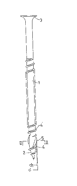
Fig. 1 is a front view of the tapping screw in
accordance with the present invention;
Fig. 2 is a sectional view taken along line II-II in
Fig. 1;
Fig. 3 is a partial front view of another embodiment;
and
Fig. 4 is a front view of a prior art tapping screw.
Referring first to Fig. 1, a shank 1 has a conical
tapered portion 2 at one end, and has at its other end a screw

~Z88980
- 4 - 04269-23 GWH:jy
head 3 formed with a + or - shaped groove to receive a driver
tip.
The shank 1 is formed with threads 4 and 4' which have
a predetermined lead angle. The thread 4 is formed on tapered
portion 2 and is separated from the thread 4' by a threadless
portion of a predetermined length which is located at the rear
part of the tapered portion 2. Drill edges 5 are located on the
threadless portion and are independent of the threads 4, 4'.
The drill edges 5 have such a large lead angle as to
be convergent to the axis of the shank 1, and have their outer
edge sharpened to form a ridge-like cutting edge, as shown ln
Fig. 2. As shown in Figs. 1 and 2, the maximum diameter d of the
drill edges S is set to be larger than the maximum thread
diameter dl at the tapered portion 2 and smaller than the maximum
thread diameter d2 at the shank. In operation, the threads 4 on
the tapered portion 2 tap a thread, which is then chipped off by
the drill edges 5. Into the hole thus made which serves as a
starting hole, the threads 4' on the rear part of the shank are
driven while tapping a thread in the wall of the hole.
The number of the threads 4 on the tapered portion
should preferably be set at 2 to 4 to achieve a balance between
the ease with which the screw can be driven the ability of the
threads to guide the screw as it is driven. The length of the
drill edges 5 should preferably be substantially the same as that
of the thread 4 on the tapered end.
As shown in Fig. 3, a thread 6 having a larger lead
angle than the remaining threads 4, 4' for a predetermined length

128~980
- 5 - 04269-28 GWH:jy
may be provided on the rear of the tapered end to serve as a
drill edge. The tip of the thread 6 or helical edge as the drill
edge should be sharpened in order to obtain a good cutting effect
as a cutting edge.
The above-described tapping screw is adapted to bite
into a substrate, lead by the thread 4 on the tapered end 2, and
then the drill edges 5 chips off the thread tapped by the thread
4 to ream the hole. Finally, the thread 4' on the main part of
the shank bites into the drilled hole which serves as a starting
hole. ~fter biting into the clamp face, the thread 4 on the
tapered end guides and pulls the screw as it further cuts into
the clamp face, thus allowing the drill edges 5 and the thread
4' to bite securely, helping the screw to stand on its own
quickly, and preventing the screw from reversing once it has been
driven in, thus imparting excellent holding power to the screw.
The drill edges 5 will help to increase the drilling speed and
facilitate the tapping by the thread 4' on the main part of the
shank. They also perform the function oE sending the chips
upward, taking advantage of their large lead and preventing the
chips from getting stuck.

Representative Drawing
A single figure which represents the drawing illustrating the invention.
Administrative Status

2024-08-01:As part of the Next Generation Patents (NGP) transition, the Canadian Patents Database (CPD) now contains a more detailed Event History, which replicates the Event Log of our new back-office solution.

Please note that "Inactive:" events refers to events no longer in use in our new back-office solution.

For a clearer understanding of the status of the application/patent presented on this page, the site Disclaimer , as well as the definitions for Patent , Event History , Maintenance Fee  and Payment History  should be consulted.

Event History

Description Date
Inactive: Reversal of expired status 2012-12-05
Time Limit for Reversal Expired 2008-09-17
Letter Sent 2007-09-17
Inactive: Office letter 2006-12-06
Inactive: Corrective payment - s.78.6 Act 2006-11-28
Inactive: Office letter 2006-11-10
Inactive: Corrective payment - s.78.6 Act 2006-10-18
Inactive: Entity size changed 2002-06-27
Grant by Issuance 1991-09-17

Abandonment History

There is no abandonment history.

Fee History

Fee Type Anniversary Year Due Date Paid Date
MF (category 1, 6th anniv.) - standard 1997-09-17 1997-06-04
MF (category 1, 7th anniv.) - standard 1998-09-17 1998-06-18
MF (category 1, 8th anniv.) - standard 1999-09-17 1999-06-15
MF (category 1, 9th anniv.) - standard 2000-09-18 2000-06-05
MF (category 1, 10th anniv.) - standard 2001-09-17 2001-05-31
MF (category 1, 11th anniv.) - standard 2002-09-17 2002-06-14
MF (category 1, 12th anniv.) - standard 2003-09-17 2003-06-03
MF (category 1, 13th anniv.) - standard 2004-09-17 2004-08-16
MF (category 1, 14th anniv.) - standard 2005-09-19 2005-08-17
MF (category 1, 15th anniv.) - standard 2006-09-18 2006-08-16
2006-10-18
2006-11-28
Owners on Record

Note: Records showing the ownership history in alphabetical order.

Current Owners on Record
YAO SEIBYO CO., LTD.
Past Owners on Record
SEIICHIRO TAKASAKI
Past Owners that do not appear in the "Owners on Record" listing will appear in other documentation within the application.
Documents

To view selected files, please enter reCAPTCHA code :


To view images, click a link in the Document Description column. To download the documents, select one or more checkboxes in the first column and then click the "Download Selected in PDF format (Zip Archive)" or the "Download Selected as Single PDF" button.

List of published and non-published patent-specific documents on the CPD .

If you have any difficulty accessing content, you can call the Client Service Centre at 1-866-997-1936 or send them an e-mail at CIPO Client Service Centre.


Document
Description 
Date
(yyyy-mm-dd) 
Number of pages   Size of Image (KB) 
Drawings 1993-10-22 1 15
Claims 1993-10-22 2 33
Abstract 1993-10-22 1 9
Cover Page 1993-10-22 1 10
Descriptions 1993-10-22 5 152
Representative drawing 2001-07-18 1 5
Maintenance Fee Notice 2007-10-29 1 171
Fees 2006-08-16 1 34
Correspondence 2006-11-10 1 22
Correspondence 2006-12-06 1 13
Fees 1996-06-11 1 49
Fees 1995-06-02 1 55
Fees 1994-06-10 1 52
Fees 1993-07-14 1 48