Language selection

Search

Patent 1289234 Summary

Third-party information liability

Some of the information on this Web page has been provided by external sources. The Government of Canada is not responsible for the accuracy, reliability or currency of the information supplied by external sources. Users wishing to rely upon this information should consult directly with the source of the information. Content provided by external sources is not subject to official languages, privacy and accessibility requirements.

Claims and Abstract availability

Any discrepancies in the text and image of the Claims and Abstract are due to differing posting times. Text of the Claims and Abstract are posted:

  • At the time the application is open to public inspection;
  • At the time of issue of the patent (grant).
(12) Patent: (11) CA 1289234
(21) Application Number: 1289234
(54) English Title: RAILWAY SIGNALLING SYSTEM
(54) French Title: SYSTEME DE SIGNALISATION POUR CHEMIN DE FER
Status: Expired and beyond the Period of Reversal
Bibliographic Data
(51) International Patent Classification (IPC):
  • B61L 03/08 (2006.01)
  • B61L 03/22 (2006.01)
  • B61L 19/06 (2006.01)
  • B61L 25/06 (2006.01)
(72) Inventors :
  • NORTON, DAVID J. (United Kingdom)
(73) Owners :
  • WESTINGHOUSE BRAKE AND SIGNAL COMPANY LIMITED
(71) Applicants :
  • WESTINGHOUSE BRAKE AND SIGNAL COMPANY LIMITED (United Kingdom)
(74) Agent: GOWLING WLG (CANADA) LLP
(74) Associate agent:
(45) Issued: 1991-09-17
(22) Filed Date: 1987-07-14
Availability of licence: N/A
Dedicated to the Public: N/A
(25) Language of filing: English

Patent Cooperation Treaty (PCT): No

(30) Application Priority Data:
Application No. Country/Territory Date
8618112 (United Kingdom) 1986-07-24

Abstracts

English Abstract


ABSTRACT
A railway signalling system includes a plurality
of trackside equipments (11,12) and means (1,2,3,4,6,
15,16) for transmitting control information to
the equipments and receiving status information
therefrom, each of the trackside equipments being
provided with a respective microprocessor (13 or
14) via which such control information is transmitted
from the said means to the equipment and via which
such status information is received by said means
from the equipment.


Claims

Note: Claims are shown in the official language in which they were submitted.


The embodiments of the invention in which an exclusive
property of privilege is claimed, are defined as follows:
1. A railway signalling system comprising:
a plurality of trackside equipments;
means for transmitting control information to said
equipments and for receiving status information
therefrom;
a plurality of microprocessors at the trackside,
each of which microprocessors is coupled to a
respective one of said trackside equipments; and
means coupling said microprocessors to said means
for transmitting and receiving, for transmitting said
control information to said equipments through the
respective ones of said microprocessors and for
receiving said status information from said equipments
through the respective ones of said microprocessors.
2. A system according to claim 1, wherein said means
for transmitting control information and receiving
status information comprises means at a control station
for setting up routes within the system and a bi-
directional communication link via which said means
communicates with the microprocessors and the latter
communicate with said means.
3. A system according to claim 2, wherein said bi-
directional link comprises a pair of twisted wires.
4. A system according to claim 2, wherein said bi-
directional link comprises an optical fibre.
5. A system according to claim 2, wherein at least
some of said trackside equipments are arranged in a
group, there being provided for said group, common
control apparatus which includes a further
microprocessor coupled to said bi-directional link for

communication therewith, a respective bi-directional
communication link being connected between the
microprocessor of each of the trackside equipments of
the group and said further microprocessor for
communicating with the further microprocessor.
6. A system according to claim 5, wherein the
respective bi-directional communication link of the
microprocessor of at least one of the trackside
equipments of said group comprises a pair of twisted
wires.
7. A system according to claim 5, wherein the
respective bi-directional communication link of the
microprocessor of at least one of the trackside
equipments of said group comprises an optical fibre.
8. A system according to claim 2, wherein the
microprocessors of at least some of said trackside
equipments are provided with respective bi-directional
communication links via which they communicate directly
with the first-mentioned bi-directional communication
link.
9. A system according to claim 8, wherein at least
one of said respective bi-directional communication
links comprises a pair of twisted wires.
10. A system according to claim 8, wherein at least
one of said respective bi-directional communication
links comprises an optical fibre.
11. A system according to claim 1, wherein at least
some of said trackside equipments comprise sets of
signal lights.
-6-

12. A system according to claim 1, wherein at least
some of said trackside equipments comprise points
machines.
13. A railway signalling system comprising:
a) a plurality of sets of trackside lights each
having a respective microprocessor at the
trackside connected thereto;
b) a plurality of trackside points machines each
having a respective microprocessor at the
trackside connected thereto; and
c) first means, for transmitting control
information to said sets of signal lights and
points machines and receiving status information
therefrom, including;
d) second means, at a control station, for
setting up routes within the system and a bi-
directional communication link via which said
first means communicates with said microprocessors
to transmit control information from said first
means to the sets of signal lights and the points
machines and said microprocessors communicate with
said first means so that status information is
received by said first means from the sets of
signal lights and the points machines.
-7-

Description

Note: Descriptions are shown in the official language in which they were submitted.


1289234
A RAILWAY SIGNALLING SYSTEM
The present invention relate~ to a railway
signalling system, more particularly one in which
information is transmitted to and from trackside
equipment such as sets of signal lights and/or points
machines.
Problems associated with the transmission of
information to and from trackside equipment in a railway
signalling system are the installation of the signalling
means, the cost of testing of the signalling means
after installation, and maintenance of the overall
system, including the signalling means.
According to the present invention, there -is
provided a railway signalling system including a
plurality of trackside equipments and means for
transmitting control information to the equipments
and receiving status information therefrom, wherein
each of the trackside equipments is provided at the
trackside with a respective microprocessor via which
such control information is transmitted from the said
means to the equipment and via which such status
information is received by said means from the equipment.
The present invention will now be described, by
way of example, with reference to the accompanying
drawings, in which :-
Figure 1 is a block diagram of a system embodying
: an example of the invention; and
Figure 2 is a block diagram of a modified version
of the system of Figure 1.
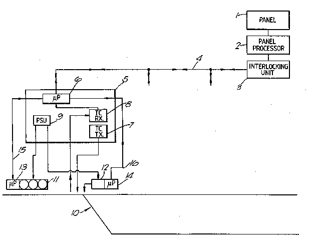
Referring to Figure 1, one example of a railwaysignalling system embodying the present invention
is illustrated. A panel 1 at a central control station
is used for setting up routes in the system by setting
up conditions for sets of trackside signal lights

-` 1289234
--2--
and trackside points machines in the system. Panel 1
interfaces via a panel processor 2 with an interlocking
unit 3 from which control data for the sets of signal
lights and points machines is sent and which receives
data related to the status of the sets of signal lights
and points machines. The interlocking unit 3 operates
according to predetermined safety routines, and data
is sent to and from it via a bi-directional communication
link, in the example a physical link 4 which could
be a pair of optical fibres or a pair of twisted wires.
Coupled to the link 4 are a plurality of cases
(only one shown). In each case 5 respectively
there are: a microprocessor 6; a track circuit
transmitter 7; a track circuit receiver 8; and a power
supply unit 9 for energising microprocessor 6, transmitter
7 and receiver 8 by suitable low voltages. Reference
numeral 10 denotes a section of railway track having
a plurality of sets of trackside signal lights 11
and trackside points machines 12 (only one of each
being shown). In Figure 1, components in one case 5
are shown as controlling one set of signal lights
11 and one points machine 12, although they could
control up to four or five of each for example. Each
set of signal lights 11 and each points machinel2 is
supplied with a suitable high voltage from the power
supply unit 9 of the associated case 5. Also, each
set of signal lights 11 is provided with a respective
microprocessor 13 and each points machine 12 is provided
with a respective microprocessor 14. ~ach microprocessor
13 is coupled via a bi-directional communication link
(for example, a pair of twisted wires or a pair
of optical fibres) with the microprocessor 6 of the
associated case 5; and each microprocessor 14 is coupled
~; via a bi-directional connunication link 16 (for example,a pair of twisted wires or a pair of optical fibres) with the
microprocessor 6 of the associated case.
In operation of the system, the interlocking~ 3 serially
:;~
'~
- - . . ~ ~
.
,
- :

1289234
--3
tra~smits coded control data via the link 4, the
data destined for each case 5 being coded accordingly.
The mi~oprocessor 6 of each case 5 decodes the data
intended for the respective case and issues control
instructions via the or each link 15 and the or each
link 16. On receipt of an instruction via the respective
link 15 (for example, "Illuminate green light"),
each microprocessor 13 causes its set of signal lights 11
to assume the appropriate condition and the microprocessor
signals back to the microprocessor 6 via the link
that the appropriate condition has been assumed
(for example, "Green light illuminated"). On receipt of
an instruction via the respective link 16 (for example,
"Set points to normal"), each microprocessor
14 causes its points machine to assume the appropriate
condition and the microprocessor signals back to
the microprocessor 6 via the link 16 that the appropriate
condition has been assumed (for example, "Points
set to normal"). Also,each microprocessor 13 and
each microprocessor 14 signals back via its link
or 16 to the microprocessor 6 of the associated
case 5 information reporting on self-testing routines
it carries out on itself. The microprocessor 6 of
each case 5 also receives information from the respective
track circuit receiver 8, the latter receiving information
from a respective track circuit fed from the track
circuit transmitter 7 of the case 5.
Finally, each microprocessor 6 transmits to the
interlocking unit 3 via the link 4 data related to
the information received via the or each link 15
and the or each link 16 and from the track circuit
receiver 8.
In the system of Figure 2, each of cases 5 does not
include a microprocessor 6. Instead the microprocessors
13 and 14 are adaPted to communicate directly with
~:
: :
., - .
, ~. : ~ . , , -
~:-` , : , ' , ' -
. . ~
: .
: ' .

1289234
--4--
the interlocking unit 3 via their bi-directional
communication links 15 and 16 and the link 4; and
each track circuit receiver 8 has a microprocessor
17 which sends data from the receiver to the interlocking
unit 3 via a communication link 18 (for example, a
wire or an optical fibre) and the link 4. Instead
of power supply units 9 supplying high voltage to
the sets of signal lights 11 and points machines 12,
each of the latter could have its own respective power
supply unit for this purpose.
Advantages of the above-described systems are
ease of intallation and reduced costs of wiring and
installation; reduced testing costs on site after
installation since the use of microprocessors enables
full testing prior to despatch and installation of
equipment; and reduced overall system engineering
costs.
: 30
::
::
~ .
.. , - .

Representative Drawing
A single figure which represents the drawing illustrating the invention.
Administrative Status

2024-08-01:As part of the Next Generation Patents (NGP) transition, the Canadian Patents Database (CPD) now contains a more detailed Event History, which replicates the Event Log of our new back-office solution.

Please note that "Inactive:" events refers to events no longer in use in our new back-office solution.

For a clearer understanding of the status of the application/patent presented on this page, the site Disclaimer , as well as the definitions for Patent , Event History , Maintenance Fee  and Payment History  should be consulted.

Event History

Description Date
Inactive: IPC from MCD 2006-03-11
Inactive: Adhoc Request Documented 1996-09-17
Time Limit for Reversal Expired 1996-03-17
Letter Sent 1995-09-18
Grant by Issuance 1991-09-17

Abandonment History

There is no abandonment history.

Owners on Record

Note: Records showing the ownership history in alphabetical order.

Current Owners on Record
WESTINGHOUSE BRAKE AND SIGNAL COMPANY LIMITED
Past Owners on Record
DAVID J. NORTON
Past Owners that do not appear in the "Owners on Record" listing will appear in other documentation within the application.
Documents

To view selected files, please enter reCAPTCHA code :


To view images, click a link in the Document Description column (Temporarily unavailable). To download the documents, select one or more checkboxes in the first column and then click the "Download Selected in PDF format (Zip Archive)" or the "Download Selected as Single PDF" button.

List of published and non-published patent-specific documents on the CPD .

If you have any difficulty accessing content, you can call the Client Service Centre at 1-866-997-1936 or send them an e-mail at CIPO Client Service Centre.

({010=All Documents, 020=As Filed, 030=As Open to Public Inspection, 040=At Issuance, 050=Examination, 060=Incoming Correspondence, 070=Miscellaneous, 080=Outgoing Correspondence, 090=Payment})


Document
Description 
Date
(yyyy-mm-dd) 
Number of pages   Size of Image (KB) 
Drawings 1993-10-21 2 28
Claims 1993-10-21 3 93
Abstract 1993-10-21 1 17
Descriptions 1993-10-21 4 138
Representative drawing 2000-08-13 1 10
Fees 1993-10-14 1 40
Fees 1994-08-29 1 42