Language selection

Search

Patent 1289760 Summary

Third-party information liability

Some of the information on this Web page has been provided by external sources. The Government of Canada is not responsible for the accuracy, reliability or currency of the information supplied by external sources. Users wishing to rely upon this information should consult directly with the source of the information. Content provided by external sources is not subject to official languages, privacy and accessibility requirements.

Claims and Abstract availability

Any discrepancies in the text and image of the Claims and Abstract are due to differing posting times. Text of the Claims and Abstract are posted:

  • At the time the application is open to public inspection;
  • At the time of issue of the patent (grant).
(12) Patent: (11) CA 1289760
(21) Application Number: 1289760
(54) English Title: WATER COOLER WITH ONE-PIECE REMOVABLE WELL
(54) French Title: REFROIDISSEUR D'EAU A CUVETTE MONOPIECE AMOVIBLE
Status: Expired and beyond the Period of Reversal
Bibliographic Data
(51) International Patent Classification (IPC):
  • B67D 7/80 (2010.01)
(72) Inventors :
  • DESROSIERS, ANDRE (Canada)
(73) Owners :
  • PRODUITS ADDICO INC. (LES)
(71) Applicants :
  • PRODUITS ADDICO INC. (LES) (Canada)
(74) Agent: NORTON ROSE FULBRIGHT CANADA LLP/S.E.N.C.R.L., S.R.L.
(74) Associate agent:
(45) Issued: 1991-10-01
(22) Filed Date: 1987-12-11
Availability of licence: N/A
Dedicated to the Public: N/A
(25) Language of filing: English

Patent Cooperation Treaty (PCT): No

(30) Application Priority Data: None

Abstracts

English Abstract


ABSTRACT OF THE DISCLOSURE
A water cooler comprising a support base having a
top wall with a top opening therein. A refrigerating coil is
located inside the base and supported a predetermined
distance from the top opening. A one-piece removable well
having a liquid retaining reservoir and a support flange
wall, is removable supported on the top wall of the support
base with the support flange in support contact on the top
wall and the reservoir extending through the top opening with
a lower portion of the reservoir disposed internally of the
refrigerating coil and in close fit therewith. The reservoir
has an upper portion with separating means being provided for
separating the lower and upper portions and permitting liquid
flow therebetween. The support flange is provided with a
support wall disposed about the reservoir for supporting a
liquid container having a bottle neck. The container is
supported in an inverted position with the bottle neck
extending into the upper portion of the reservoir above the
separating means. The container support wall permits air
flow between the reservoir upper portion and atmosphere and
about the container.


Claims

Note: Claims are shown in the official language in which they were submitted.

The embodiments of the invention in which an exclusive
property or privilege is claimed are defined as follows:
1. A water cooler comprising a support base having a
top wall with a top opening therein, a refrigerating coil
inside said base and supported a predetermined distance from
said top opening, a one-piece removable well having a liquid
retaining reservoir and a support flange wall, said removable
well being removably supported on said top wall with said
support flange in support contact on said top wall and said
reservoir extending into said top opening with a lower
portion of said reservoir disposed internally of said
refrigerating coil in close fit therewith, said reservoir
having an upper portion, separation means for separating said
lower and upper portions to define a lower and upper chamber
and permitting liquid flow therebetween, said support flange
having support means about said reservoir for supporting a
liquid container having a bottle neck in an inverted position
with said bottle neck extending into said upper chamber of
said resevoir spaced above said separation means, said
support means permitting air flow between said reservoir
upper and outside air and about said container, and
dispensing means connected to said removable well for
dispensing liquid therefrom.
2. A water cooler as claimed in claim 1, wherein there
is further provided a cover removably positionable over said
top wall about said support flange for concealing said liquid
container when on said support flange.
3. A water cooler as claimed in claim 1, wherein said
separation means is a removable disc wall supported inside
said reservoir by circumferential support means, a passage in
said wall for the passage of a conduit for communicating a
- 7 -

dispensing valve with the inner area of said reservoir upper
chamber above said disc wall, and one or more orifices for
permitting said liquid flow from said reservoir upper chamber
to said lower chamber.
4. A water cooler as claimed in claim 3, wherein said
reservoir is molded with a circumferential flange wall
intermediate said upper and lower portion, said disc being
supported by said flange wall.
5. A water cooler as claimed in claim 3, wherein said
disc is a circular disc, said reservoir being a cylindrical
reservoir, said disc having an outer diameter smaller than
the diameter of said reservoir upper portion, and a plurality
of spacer ribs formed about said disc for supporting said
disc with said outer diameter edge spaced from a side wall of
said upper chamber to permit liquid flow from said upper
chamber to said lower chamber about said disc.
6. A water cooler as claimed in claim 1, wherein said
reservoir is a cylindrical reservoir, said support means of
said support flange being constituted by an inwardly inclined
annular flange wall disposed about an open top end of said
reservoir and molded therewith, and spacer means on an upper
surface of said annular flange wall for supporting portions
of said liquid container spaced from said inwardly inclined
annular flange wall.
7. A water cooler as claimed in claim 6, wherein said
spacer means are ribs disposed about said annular flange wall
and aligned with diametrical axes of said reservoir.
- 8 -

8. A water cooler as claimed in claim 2, wherein said
support flange wall is provided with a circumferential
reinforcing rib which sits on said top wall of said support
base, said support flange wall being configured to the
cross-section of said support base and frictionally engaging
a bottom contour edge of said cover which is of the same
cross-section as said support base.
9. A water cooler as claimed in claim 3, wherein said
support base is an elongated vertical housing provided with a
liquid dispensing portion recessed in a side wall thereof, a
pair of dispensing valves in said dispensing portion, a drip
tray spaced below said valves and disposed in said housing,
each valve having a conduit communicating with a respective
one of said upper and lower chambers of said reservoir.
10. A water cooler as claimed in claim 9, wherein a
thermal insulating open top end cylinder is supported in said
support base below said top opening in said top wall, said
refrigerating coil being disposed inside said cylinder
adjacent a bottom wall thereof.
11. A water cooler as claimed in claim 1 wherein said
dispensing means comprises two valves each having conduit
means detachably connected to said removable wall, each
conduig having an intake orifice associated with a respective
one of said lower and upper chamber of said well, said liquid
in said lower chamber being cooler than said liquid in said
upper chamber.
- 9 -

Description

Note: Descriptions are shown in the official language in which they were submitted.


BACKGROUND OF THE INVENTION
Field of the invention
The present invention relates to an improved water
cooler for dispensing water provided in bottle containers and
wherein the bottle container is concealed inside an upper
par-t of the water cooler and wherein the well of the cooler
is molded as a single piece and easily removed for cleaniny
and servicing.
Description of Prior Art
Various type of water coolers are known, but these
mostly consist in an open top end base in which a water
bottle is placed in an inverted position with the neck of the
bottle extending in-to a well of the base. A disadvantage of
such water coolers is that, they are not of an aesthetically
pleasing design, they are not totally hygienic due to the
fact that the well is continuously exposed to environmental
dust. Furthermore, known water coolers are very difficult to
service and repair and to maintain clean. Known coolers also
only supply refrigerated water and do not provide access to
the water directly in the bottle which is at room
temperature.
SUMMARY OF INVENTION
A feature of the present invention is to provide an
improvedwater cooler construction which substantially
overcomes all of the above mentioned disadvantages of the
known prior art and provides additional advantages.
According to the above feature, from a broad
aspect, the present invention provides a water cooler
comprising a support base having a top wall with a top
opening therein. A refrigerating coil is disposed inside the
base and supported a predeterminecl distance from the top
openina. A one-piece removable well, having a liquid
- 1 -

retaining reservoir and a support flange wall, is removably
supported on the top wall with the support flange in support
contact on the top wall and the reservoir extending in to the
top opening wlth a lower portion the reservoir disposed
in-ternally of the refrigerating coil and in close fif
therewith. The reservoir has an upper portion r~7ith
separation means separating the lower and upper portion to
define a lower and upper chamber and permitting li~uid flow
therebetween. The support flange has support means about the
reservoir for supporting a liquid container, having a bottle
neck, in an inverted position with the bottle neck extending
into the upper chamber of the reservoir above the separating
means. The support means permits air flow between the
reservoir upper chamber and atmosphere and about the
container.
A preferred embodiment of the present invention
will now be described with reference to the example thereof
as illustrated in the accompanying drawings, in which
BRIEF DESCRIPTION OF DRAWINGS
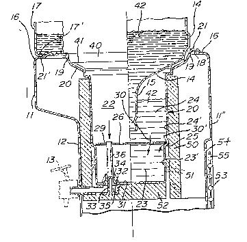
FIGURE 1 is an exploded perspective view of the
water cooler of the present invention;
FIGURE 2 is a fragmented section view showing the
top end of the support base including the removable well, and
FIGURE 3 is a plan view of the separator disc.
Description of Preferred embodiment
Referring now to the drawings, and more
particularly to Figure 1, there is shown generally at 10 the
water cooler of the present invention and comprising an
elongated vertical support base 11 having a dispensing
portion 12 which is recessed within the side wall 11' of the
housing. A pair of dispensing valves 13 are provided in an
upper end of the recess portion 12 for dispensing a liquid,

7~;0
herein water contained in a lower and upper chamber of a
reservoir, respectively,and fed by a liquid container 14. A
removable drip tray 12' is disposed in thelower part o~ the
recesses dispensing por-tion 12. The container 14 is a water
bottle having a bottle neck 15 (see Fig. 2) which is inverted
into a well provided in the top wall 16 of the support base
11, as will be described later. A cover 17 is removably
positionable over the top wall 16 to conceal the liquid
container 14 when posi-tioned on the top wall 16.
Referring now additionally to Figures 2 and 3,
there in shown the construction of the top wall 16 of the
support base 11 and a one-piece removable well 20. The top
wall 16 of the support base 11 is provided with a top opening
19 having a flange wall 18 onto which a circumferential
flange portion 21 of the removable well 20 is fit-ted. As
herein shown the well 20 is molded from plastic material as a
single piece.
The removable well 20 defines a liquid retaining
reservoir 22 which has a lower portion 23 defining a lower
chamber of slightly smaller cross-section than ~he upper
portion 24. A circumferential support flange wall 25 is
defined intermediate the lower and top portions 23 and 24 and
on which is positioned, a removable wall ordisc 26 which acts
as a separator wall.
As shown in Figure 3, the disc 26 is of circular
configuration and has an outer diameter which is smaller than
the diameter of the reservoir upper portion 24. A plurality
of spacer ribs 27 are formed abou-t the disc for supporting
the disc with the outer diameter edge 28 spaced from the
inner side wall 24' of the upper chamber 24 to permit liquid
flow from the upper chamber to the lower chamber about the

disc as shown by arrow 30'. A large hole 29 is also provided
in the disc for permitting water flow from the top chamber 24
to the lower chamber 23 in the direction of arrow 30.
The reservoir lower chamber 23 has a bottom wall 31
provided with two holes 32 (only one shown herein) into which
extends the receiving ends of two conduits, only one conduit
33 shown herein. Each conduit 33 is associated with a
respective one of the liquid dispensing taps 13. As herein
shown, the conduit 33 is sealingly connected through the hole
32 by a sealing nut 34 to compress the lower wall 31 against
a seal 35 provided about the hole 32 under the wall 31. A
flexible conduit 36 extends through the lower chamber 23 and
into the top chamber 24 through the hole 29 provided in the
disc 26. Accordingly, the upper chamber 24 is in
communication with the conduit 33. The other conduit not
shown is in communication with the lower chamber 23 and is
sealingly connected thereto by another nut 34 (not shown).
Accordingly, each of the taps 13 dispense water from the
upper and lower chamber 22 and 23, respectively. The water
in the lower chamber is maintain cooler by cooling coils 51.
The upper portion of the removable well 20 defines
an inwardly incline angular flange wall 40 to constitute a
support means for the water bottle 14 placed in an inverted
position thereon. Spacers in the form of radiating ribs 41
are spaced apart on the inclined angular flange wall 40
whereby to space the shoulder wall 41' of the bottle from the
surface 40 to permit air flow between the flange wall 40 and
the bottle and inside the upper chamber 24 whereby to prevent
a vacuum from forming therein and preventing the gravity
discharge of the liquid 42 contained within the bottle 14.

-` lZ~760
As herein shown, the ribs 41 are disposed about the angular
flange wall and aligned with diametrical axes of the
reservoir.
The support circumferential flange wall 21 is
provided with a reinforcing rib 21' which fits on the top
wall 16 of the support base 11. The circumferential flange
wall portion 21 is also configured to the cross-section
configuration of the support base, but smaller in size, and
frictionally engages the bottom contour edge 17' of the cover
17. As shown in Figure 2, a thermo insulating open top end
cylinder 50 formed of insulating foam,is supported in the
support base by suitable means (not shown) below the top
opening 19 in the top wall 16. The refrigerating coil 51 is
disposed inside the cylinder 50 adjacent the bottom
insulating wall 52 whereby to be in close fit with the bottom
portion 23 of the removable well 20 when positioned in the
opening 19 and refrigerates the water in the lower chamber
23. This refrigerating coil connects to refrigerating
equipment (not shown) house within the lower portion of the
support base 11. A heat exchange grid 53 is secured adjacent
a rear opening 54 provided in the back wall 11" of the
support base 11 and hinges outwardly on hinge brackets 55 for
access to the inside of the support base, when required for
servicing.
As can be seen, the entire water cooler is easy to
assemble and disassemble when required for servicing. The
one-piece removable well 20 is detached entirely from the
support base 11 by the removal of two lock nuts 34 provided
inside the reservoir under the removable disc 26. The base
and cover are constructed of plastic material and
blow-molded.

~2~
It is within the ambit of the present in~ention to
cover any obvious modifications of the ex~mples of the
preferred embodiment described herein, provided such
modifications fall within the scope of the appended claims.
-- 6 --

Representative Drawing
A single figure which represents the drawing illustrating the invention.
Administrative Status

2024-08-01:As part of the Next Generation Patents (NGP) transition, the Canadian Patents Database (CPD) now contains a more detailed Event History, which replicates the Event Log of our new back-office solution.

Please note that "Inactive:" events refers to events no longer in use in our new back-office solution.

For a clearer understanding of the status of the application/patent presented on this page, the site Disclaimer , as well as the definitions for Patent , Event History , Maintenance Fee  and Payment History  should be consulted.

Event History

Description Date
Inactive: Reversal of expired status 2012-12-05
Inactive: IPC deactivated 2011-07-26
Inactive: First IPC derived 2010-02-01
Inactive: IPC from MCD 2010-02-01
Inactive: IPC expired 2010-01-01
Time Limit for Reversal Expired 2008-10-01
Letter Sent 2007-10-01
Letter Sent 2006-09-11
Inactive: Office letter 2005-10-03
Inactive: Entity size changed 2002-07-16
Inactive: Late MF processed 2002-07-03
Grant by Issuance 1991-10-01

Abandonment History

There is no abandonment history.

Fee History

Fee Type Anniversary Year Due Date Paid Date
MF (category 1, 6th anniv.) - small 1997-10-01 1997-09-09
MF (category 1, 7th anniv.) - small 1998-10-01 1998-09-21
MF (category 1, 8th anniv.) - small 1999-10-01 1999-09-13
MF (category 1, 9th anniv.) - small 2000-10-02 2000-02-16
Reversal of deemed expiry 2001-10-01 2001-09-14
MF (category 1, 10th anniv.) - standard 2001-10-01 2001-09-14
MF (category 1, 11th anniv.) - standard 2002-10-01 2002-09-25
MF (category 1, 12th anniv.) - standard 2003-10-01 2003-09-30
MF (category 1, 13th anniv.) - standard 2004-10-01 2004-07-13
MF (category 1, 14th anniv.) - standard 2005-10-03 2005-09-16
MF (category 1, 15th anniv.) - standard 2006-10-02 2006-09-08
Owners on Record

Note: Records showing the ownership history in alphabetical order.

Current Owners on Record
PRODUITS ADDICO INC. (LES)
Past Owners on Record
ANDRE DESROSIERS
Past Owners that do not appear in the "Owners on Record" listing will appear in other documentation within the application.
Documents

To view selected files, please enter reCAPTCHA code :


To view images, click a link in the Document Description column. To download the documents, select one or more checkboxes in the first column and then click the "Download Selected in PDF format (Zip Archive)" or the "Download Selected as Single PDF" button.

List of published and non-published patent-specific documents on the CPD .

If you have any difficulty accessing content, you can call the Client Service Centre at 1-866-997-1936 or send them an e-mail at CIPO Client Service Centre.


Document
Description 
Date
(yyyy-mm-dd) 
Number of pages   Size of Image (KB) 
Cover Page 1993-10-22 1 11
Claims 1993-10-22 3 102
Abstract 1993-10-22 1 26
Drawings 1993-10-22 1 44
Descriptions 1993-10-22 6 187
Representative drawing 2000-08-14 1 24
Late Payment Acknowledgement 2002-07-16 1 170
Maintenance Fee Notice 2007-11-13 1 171
Fees 2002-07-03 1 46
Correspondence 2006-09-11 1 12
Correspondence 2005-10-03 1 15
Correspondence 2006-08-22 1 28
Fees 1996-09-16 1 63
Fees 1995-09-22 1 54
Fees 1994-09-12 1 59
Fees 1993-09-02 1 52