Note: Descriptions are shown in the official language in which they were submitted.
9~21
-- 2
BACKGROUND OF THE INVENTION
Field of the invention
. .
. The present invention relates to a boss cap of a
screw propeller, particularly to a screw propeller boss cap
- with fins.
. Description of the prior art
. . .
In order to improve the characteristics of a screw
propeller, particularly the propeller efficiency, extensive
and intensive researches have already been made by engineers
with respect to the technical design of number, shape,
developed area, pitch, etc. of blades and now their fruits
materially have been brought forth to a nearly maximum
extent. Thus it is extremely difficult to expect any future
drastic improvement of the propeller characteristics through
researches on these items.
On the other hand, it has been known that the
propeller efficiency of a screw propeller is low in the
proximity of its boss. For this reason, it has been
proposed for several times to provide a small diameter
propeller at the rear stream side of the main propeller so
that the propeller efficiency in the proximity of its boss
.
, ~ ' ' ' - ''
. . ~ ~ - .
'- ~
', '
3 --
may be raised, for example, in the Japanese Utility Model
Laid-opens Nos. 30,195/81 and 139,500/82. It seems however
that such idea in fact was not successful, probably for the
reason that the thrust does not so much increase as the
torque increases and thus the propeller efficiency is not so
improved as expected.
SUMMA~Y OF THE INVENTION
.
An object of the present invention therefore is to
provide a new technique which enables to improve the
propeller characteristics particularly the propeller
efficiency to a considerably high extent through addition of
a boss cap with fins to a propeller.
As shown in the attached drawing of Eig. 3 (prior
art technique), an ordinary screw propeller 31 comprises a
plurality of blades 33 provided in a equidistance around the
periphery of a boss 32 and is connected through the boss 32
to a rotational drive shaft 34. On an end opposite to the
drive shaft 34 of the boss 32, a conical boss cap 35 is
mounted in order to reduce vortices generated downstream of
the boss 32 as much as possible.
The present inventors have focused their attention
on the fact that even in the rear stream of such propeller
.. . . .
~ ' ,
- ~ - .
1~982~
71g93-2
boss cap, a considerable hub vortex 36 is generated and, in the
thought that the prior a~t small diameter additional propeller
would have increased such hub YOrteX, have made intensive
researches seeking to find any other means for reducinq such hub
vortex. Finally it has been found tha~ the addition of a boss cap
with fins to a propeller can reduce such hub vor~ex and in effect
can increase the propeller efficiency.
Thus the present invention provides in combination: a
screw propeller having a hub and a plurality of propeller blades
thereon each havlng a leading edge toward a front of the propeller
and a tralllng edge toward the rear of the propeller and a root
along a root line on the hub extending from the leading edge to
the trailing edge, said roots lying along a line at a pitch angle
to a plane perpendicular to the axis of rotation of said
propeller; and a cap body having a front cap mounting end mounted
on said hub at the rear of said propeller, and a rear end, a
plurality of fins mounted on said cap body at intervals spaced
around the periphery of said cap body, (1) the number o~ fins
belng the same as the number of propeller blades and respectively
corresponding to the propeller blades, (ii) sald fins being
inclined at an angle to the line along which the root of the
corresponding propeller blade lies, which angle is from -20 to
+30 relative to the rotational direction of the screw propeller
and is selected to receive`a stream from the propeller blades at a
side facing toward the propeller blades, and being inclined at a
rake angle RA which is -30 ~ RA c 0 relative to the direction of
rotation of said screw propeller, and said fins having leading
~.
71993-2
edges which are toward said propeller and which are behind the
rear end of the roots of said propeller blades and between lines
starting respectively from the leading and trailing edges of the
roots of the propeller blades and extending rearwardly in parallel
to the axis of rotation of said propeller, said fins being
substantially smaller in blade area than the propeller blades and
having roots along said cap body, the ends of the roots of
trailing edges of said fins spaced in the circumferential
direction of said cap body and being spaced toward said propeller
from the rear end of said cap body; and (iii) the outer diametric
dimension of said fins from the axis of said cap being larger than
the diameter of said cap body at the rear of said propeller hub
and no larger than 33% of the outer diametric dimension of said
screw propeller as measured from the axis of rotation of the screw
propeller.
4a
<~
,:~
:, :' .,
: ~ . , ~ . ' ~ . : -
, ~' , ' -' .
l~9~Xl
5 -
The fins provided according to the present
invention are not those for generating a thrust by
themselves, hut for guiding the water stream rearward of the
boss cap to a direction to reduce the generation of the hub
vortex.
Owing to such guide effect, the hub vortex in the
rearward of the boss cap is diffused and thus the drag force
induced by the vortex on a propeller blade plane is reduced
and as the result the propeller characteristics particularly
the propeller efficiency are greatly improved without
remarkable increase of the torque.
Accordingly, as a general tendency, the present
invention gives a particularly higher effect to a propeller
having a higher pitch ratio ~H/D) which generates a stronger
hub vortex.
As shown in the embodiments of the present
invention hereinafter, the fins may be provided to have a
rake angle or a positive or negative camber against the boss
cap.
BRIEF DESCRIPTION OF THE DRAWINGS
Fig. 1 is a front view of a propeller on which an
..
9821
embodiment of the propeller boss cap with fins of the
present invention is mounted, and Fig. 2 is a side view of
the Fig. 1.
Fig. 3 is a side view similar to the Fig. 2, but
shows a propeller and a boss cap of prior art technique
without fins together with a hub vortex generated rearward
of the boss cap.
Fig. 4 is a side view partly shown in the section
of a propeller characteristics measurement apparatus used in
the experiments.
Fig. 5 is a plan view showing plane shape of the
fins used in the experiments and Fig. 6 is a side view
showing the mounting positions of the fins to the propeller
boss cap.
Fig. 7 shows the propeller characteristics curves
obtained in the Experiment No. 1 and Figs. 8-10 show the
schematic illustrations representative of the relative
positions of the propeller blades roots and the fins in the
Experiments Nos. 2-4, respectively.
Fig. 11 is a side view to show the rake angle of
the fins in the Experiment No. S and Fig. 12 is an A-A line
,
12~2~ .
sectional view of the Fig. 11.
Fig. 13 is a schematic illustration similar to the
Figs. 8-10, but showing the relative positions of the
propeller blades roots and the fins in the Experiment No. 6.
Fig. 14 is a diagram showing the results of the
Experiment No. 7.
DESCRIPTION OF THE PREFERRED EMBODIMENTS
Some embodiments of the present invention will be
explained in detail with reference to the attached drawings.
Tests are made in a water tank, using models of
propellers having the data as shown in the following table
1. The water tank is of a circular stream type and has an
observational part of scales 5.0 m (length) X 2.0 m (width) X
1.0 m (depth). The maximum flow rate is 2.0 m/sec and the
uniformity of the flow rate is within 1.5~.
Table 1
Type CP24 CP26
Diameter (mm) 220.0 220.0
Pitch ratio 0.8 1.2
~2~9821
-- 8 --
Developed ~lade area ratio 0.55 0.55
Boss ratio 0.18 0.18
Blade thikness ratio 0.05 0.05
Blade cross section shape MAU MAU
Blade number 4 4
In Fig. 4, a side view of a propeller
characteristics measurement apparatus is shown partly by a
section. This apparatus is located in the observational
part of said water tank by securing its propeller open boat
41 to a rigid carrier (not shown) placed above the water
tank. The boat 41 has a drive mechanism 43 to rotate a
propeller 42 which may detachably be attached to its tip
end, a thrust detector 44 and a torque detector 45.
Although not shown in the Fig. 4, a propeller
rotating speed i5 measured by a digital counter TM-225
(product of Ono Measurement Instruments company, Japan) and
a flow rate by a combination of a JIS type Pitot tube and a
differential pressure converter DLPU-0.02 (product of Toyo
Boldwin company, Japan). The analogue signals of such
thrust, torque and flow rate represented by the differential
pressure, etc. are converted to digital signals through an
A/D converter provided in a microprocessor located in a
separate controller and processed into physical data which
then are printed by a pinter or plotted by a plotter.
~'
-
; .
-
~X~98~
A thrust coefficient (KT) and a torque coefficient(KQ) are measured under different advance coefficients (J)
adjusted by changing the flow rate while keeping the
propeller rotating speed approprimately constant within the
range of 7.5-9.0 r.p.s.. The depth in water of the
propeller center is 300 mm and the direction of water flow
is as shown by an arrow in the Fig. 4.
As a boss cap to be mounted on the propeller
models, a cap of a rounded conical shape having a base
diameter of 35 mm and a height of 25.6 mm is prepared. The
cap may be mounted on the propeller by any known means and
in these experiments a bolt-nut securing is employed.
As fins to be provided on the boss cap, those
having six different triangular shapes (A)-~F) shown by a
plan view in Fig. 5 are prepared from flat plates of l mm
thickness to have the dimensions as shown in the following
table 2.
Table 2
Fin shape Width Height
(X-axis direction) (Y-axis direction)
. _ _ _ . .
(A) 20 mm 20 mm
(B) 26 mm 16.5 mm
1~9~1
-- 10 --
(C) 26 mm 21 mm
(D) 26 mm 28.5 mm
(E) 26 mm 34 mm
(F) 26 mm 39.5 mm
Fig. 6 shows the relative positions of the fins
and the boss cap. In this Eig. 6, a rear end O of a root 62
of a propeller blade 61 is set on the propeller axis 63 as a
reference point. In this specification, a peripheral
distance from the front end of a fin 64 to the plane
including the reference point O and the propeller axis 63 is
called "a" (positive in the direction of propeller rotation
shown by an arrow). A surface distance from the front end
of the fin 64 to a periphery including the reference point O
is called "b". The angle of the fin 64 against plane normal
to the propeller axis is called "Alpha". The geometric
pitch angle of the propeller blade root 62 is called
"Epsilon".
In this specification, the geometric pitch angle
"Epsilon" of a propeller blade root is one based upon a
nose-tail line of the propeller blade root. More precisely,
two surfaces of a cylindrical surface having an axis on the
propeller axis and a radius equal to the boss radius and a
propeller blade surface or its extension as a suspected
surface are considered. A cylindrical surface intercepted
,
. . '
,
~X~
by a crossing line between these two surfaces, that is, a
cylindrical section, is developed on a plane. In the
developed vlew, an angle between a nose-tail line of the
blade section defined by the developed cylindrical section
and a line normal to a generatrix of the cylindrical surface
corresponds to the "Epsilon".
The fin 64 is mounted on the boss cap in the
direction perpendicular to the sheet of the Fig. 6, when no
rake angle is given. The mounting is made, in these
experiments, by cutting a groove on the boss cap, inserting
the lower portion of the fin into the groove and fixing by
means of an adhesive, but it is of course possible and in
actual cases it is preferred to form the boss cap and the
fins integrally as one body. The broken lines shown in the
lower portions of fins in the Fig. 5 indicate crossing lines
between the fin surface and the boss cap surface after
mounting of the former on the latter.
Experiment 1
Water tank tests have been made by using the
propeller of the type CP26 (Epsilon=67.4) and the fins of
Fig. 5(C). The fins of total number 4, one for each
::
. ' :
12~9~21
- 12 -
propeller blade, are mounted on the boss cap in positions of
a=lO mm, b=5 mm and Alpha=66. In this instance, the
maximum diameter of the fins, that is, a doubled distance
(2r) between the radially remotest end of a fin (from the
propeller axis) and the propeller axis (after mounting of
the fins on the boss cap) and a propeller diameter (2R)
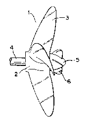
stand in a ratio r/R=0.23. Fig. l shows a front view of
thus composed propeller l, boss 2, propeller blades 3, shaft
4, boss cap 5 and fins 6; and Fig. 2 shows a side view
thereof. For comparison, tests have been made also as to
cases without fins. The thrust coefficient (KT) and the
torque coefficient (KQ) have been measured under various
advance coefficients (J) of 0.0-l.l and the propeller
efficiency (Eta= J KT/2PiKQ) has been calculated. Then an
increase ratio (dEta) of the propeller efficiency increased
from the cases without fins to the cases with fins has been
calculated by percents. The results are shown in the
following tables 3 and 4.
'; ' ~ ' ~ ' ,
1~9~
- 13 -
Table 3 ( cases without f ins )
No . J KT KQ x 10 Eta
_
0 0.000 0.4816 0.9376 0.0000
1 0.050 0.4715 0.9092 0.0413
2 0.100 0.4606 0.8823 0.0831
3 0.150 0.4489 0.8565 0.1251
4 0.200 0.4363 0.8316 0.1670
0.250 0.4230 0.8071 0.2085
6 0.300 0.4088 0.7829 0.2493
7 0.350 0.3940 0.7586 0.2893
8 0.400 0.3785 0.7342 0.3282
9 0.450 0.3623 0.7094 0.3657
0.500 0.3454 0.6839 0.4019
11 0.550 0.3281 0.6578 0.4365
12 0.600 0.3102 0.6309 0.4695
13 0.650 0.2919 0.6031 0.5007
14 0.700 0.2731 0.5743 0.5299
0.750 0.2541 0.54450.5571
16 0.800 0.2349 0.51380.5820
17 0.850 0.2154 0.48200.6046
18 0.900 0.1959 0.44940.6244
19 0.950 0.1764 0.41590.6413
1.000 0.1570 0.38170.6547
21 1.050 0.1378 0.34680.6639
22 1.100 0.1189 0.31150.6680
:,
': '
.
12~
- 14 -
Table 4 ( cases with ~ins )
.
No . J KT RQ x 10 Eta dEta ( % )
. _ . .
00.000 0.4985 0.9154 0.0000
10.050 0.4894 0.8914 0.0437 5.55
20.100 0.4785 0.8677 0.0878 5.35
30.150 0.4660 0.8440 0.1318 5.09
40.200 0.4522 0.8204 0.1755 4.81
50.250 0.4373 0.7965 0.2184 4.54
60.300 0.4215 0.7724 0.2605 4.29
70 350 0.4050 0.7479 ~.3016 4.09
80.400 0.3880 0.7~29 0.3417 3.96
90.450 0.3705 0.6973 0.3806 3.90
100.500 0.3528 0.6710 0.4184 3.95
110.550 0.3349 0.6441 0.4552 4.09
120.600 0.3168 0.6164 0.4909 4.35
130.650 0.2986 0.5879 0.5255 4.73
14 0.700 0.2803 0.5585 0.5590 5.21
0.750 0.2617 0.5284 0.5913 5.78
16 0.800 0.2430 0.4974 0.6220 6.42
17 0.850 0.2239 0.4655 0.6506 7.07
18 0.900 0.2044 0 ~ 4328 0.6762 7.66
19 0.950 0.1843 0.3994 0.6976 8.07
1.000 0.1634 0.3652 0.71~3 8.09
21 1.050 0.1417 0.3303 0.7168 7.38
22 1.100 0.1187 0.2947 0.7053 5.29
, '~`~,' ''
:
' ' '
,: .' . -
-- 15 --
Fig. 7 illustrates the results of the tables 3 and
4 showing the advance coefficient (J) in abscissa and the
thrust coefficient (KT), the torque coefficient multiplied
by ten (KQ x 10) and the propeller efficiency (Eta) in
ordinate. In this Fig. 7, curves T2, Q2 and P2 represents
KT, KQ x 10 and Eta in the table 3 and curves T3, Q3 and P3
represents KT, KQ x 10 and Eta in the table 4. From this
Fig. 7 and the table 4, it is understood that the propeller
efficiency increases about 4-8% in the overall range of
J=0.05-1.10 and particularly 7.66% at the usually employed
J=0.9.
Further, in these tests, a needle pipe is manually
put into the water from above the water tank to the close
proximity of the rear end of the boss cap to supply air
bubbles. It has been found that in the cases without fins,
a large number of air bubbles align along the propeller
axis, but in the cases with fins, air bubbles are diffused
to disappear. It is considered that a hub vortex is greatly
reduced by the merit of the fins.
Experiment 2
Tests similar to those shown in the Experiment 1
have been made, but using different positions of fins, that
is, different a, b and Alpha. The propeller efficiency
' . ~ . .
.
'"
~2~9~21
- 16 -
increase ratio obtained under the usually employed advance
coefficient (J)=0.9 is shown in the following table 5.
Table 5
No. a b Alpha Alpha- r/R dEta
(mm) (mm)(~) Epsilon() (~)
.. , . . . -- -- :
1 10 0 64 -3.4 0.25 5.49
2 15 0 61 -6.4 0.25 7.32
3* 10 5 66 -1.4 0.23 7.66
4 14 5 59 -8.4 0.23 6.39
* . . . from the data in the Experiment 1
The relative positions of fins and the propeller
blade roots are illustrated in Fig. 8, wherein the rear end
O of one propeller blade root shown in the Fig. 6 is placed
on the base line X, and the blade position is shown as a
line segment starting from the base line X with an angle
Epsilon and ha~ing a length corresponding to the length of
the nose-tail line of the propeller blade root. Another
propeller blade root adjacent to said one also is shown is a
similar manner, but at a peripheral distance between the
rear ends of them taken in the direction of the base line X.
The positions of the fins are shown by taking "a" of the
Fig. 6 in the direction of the base line X and "b" of the
. ~ i
, . : . . -
- .
.
- - : - ' ' : -
.
-
Fig. 6 in the direction of a base line Y which passesthrough the reference point O normally to the base line X.
The lengths of the fin segments correspond to the lengths of
the crossing lines between the fins and the boss cap as
shown in the Fig. 5 by broken lines. From the table 5 and
the Fig. 8, it is understood that a considerable improvement
of propeller efficiency can be obtained when the front ends
of fins are placed between the adjacent propeller blade
roots, that is, within a space between extended nose-tail
lines of the adjacent propeller blade roots.
Experiment 3
Tests similar to those of Experiment 1 have been
made, but changing on]y Alpha. The propeller efficiency
increase ratio obtained at the advance coefficient (J)=0.9
is shown in the following table 6.
Table 6
No. Alpha~) Alpha-Epsilon() r/R dEta(%)
1 45 -22.4 0.24 0.34
2 S0 -17.4 0.235 3.46
3* 66 - 1.4 0.23 7.66
4 85 17.6 0.22 3.80
S 90 22.6 O.Z2 2.19
,
- . - : ' :
: ~ ' '' ' ' .
'
., ~ ' - ~
~9~
- 18 - ,
6 95 27.6 0.22 2.38
7 100 32.6 0.22 0.77
8 105 37.6 0.22 0.47
* . ~ . from the data of Experiment 1
The results of the table 6 are shown in Fig. 9
similarly to the Experiment 2. It is understood from the
table 6 and the Fig. 9 that a considerable improvement of
propeller efficiency can be obtained within the range of -20
c Alpha-Epsilon ~30 -
Experiment 4
Tests similar to those of Experiment 2 have beenmade, but using the propeller of the type CP24
(Epsilon=57.4~) and the fins of the Fig. 5(A) and 5(C). The
propeller efficiency increase ratio obtained at the advance
coefficient (J)=0.6 usually employed for such propeller is
shown in the following table 7.
Table 7
No. a b Alpha Alpha- r/R Fin shape dEta
(mm) (mm) () Epsilon(~) (%)
.. _ . _ . _ _ .
1 0 5 80 22.6 0.21 (A) 2.03
'''~
.. .. .
. . .
.. . . . .
' ' -' : . . '
.,:, ~ .:' ' ,
.- - . ~ i
-- 19 --
2 10 17 63 5.6 0.18 (A) 3.02
3 5 12 63 5.6 0.20 (A) 2.06
4 5 9.5 63 5.6 0.21 (A) 2.32
7 63 5.6 0.215 (A) 2.84
6 10 7 63 5.6 0.23 (C) 3.93
7 10 7 57 -0.4 0.22 (C) 2.32
8 6 7 63 5.6 0.22 (C) 2.57
9 4 5 35-22.4 0.235 (C) -0.09
10 4 5 9032.6 0.22 (C) -O.lg
The results of the table 7 are shown in Fig. 10
similarly to Experiment 2. It is understood that there is
no material difference between the fin shapes (A) and (C)
and that the fin positions should satisfy the conditions
that the front end of the fin is located between the
adjacent propeller blade roots and the inclination of the
fin stands within the range of -20~Alpha-Epsilon S 30 , as
in the case of said Fig. 9.
Ex ~
The test of Experiment 4, No. 6 has been repeated,
adding rake angles of +30 to the fins~ The rake angles are
measured from the direction perpendicular to the sheet of
the Fig. 6 to the direction of rotation of the propeller.
The results are shown in the following table 8.
' ' ~ .
; , .
1~9~2~.
- 20 -
Table 8
No. a b Alpha Alpha- r/R Rake Angle dEta
(mm) (mm) () Epsilon() () (~)
6F 10 7 63 5.6 0.21+30 1.46
6M* 10 7 63 5.6 0.23 0 3.93
6B 10 7 63 5.6 0.21-30 4.47
* . . . from the data of Experiment 4
From the table 8, it is understood that there is a
tendency of further improvement of dEta when a rake angle
opposite to the rotation direction of the propeller is added
to fins. The mounting positions of fins are shown in Fig. 11
by way of a side view similar to the Fig. 6 and in Fig. 12
which is an A-A line section of the Fig. 11.
Experiment 6
The tests of Experiment 4, No. 7 has been
repeated, but by changing the number and positions of the
fins. the results are shown in the following table 9.
'~
' ' ' ~ ~ ',~ ',; ' ' ',
: . . ~ - , -' . ', ~
: . ,
12~
- 21 -
- Table 9
No.a b Alpha Alpha- r/R FindEta
(mm) (mm) (o) Epsilon() Number (%?
7~N210** 7 57 -0.4 0.22 2-0.12
7-N310** 7 57 -0.4 0.22 30.49
7-N4* 10 7 57 -0.4 0.22 42.32
7-NS10** 7 57 -0.4 0.22 5-1.12
* . . . from the data of Experiment 4
** . . . value of one specific fin; values of the
other fins correspond to the positions
determined by the quotient of 360
. divided by the number of f ins
The relative positions of the propeller blade
roots and the fins are shown in Fig. 13 by way of X-Y plane
as in the Figs. 8-10. Relative to the four propeller blade
roots Bl-B4, the fins are located, in the case of fin number
two, at the positions l/F and 2/2; in the case of fin number
three, at the positions l/F, 2/3 and 3/3; in the case of fin
:. number four, at the positions l/F, 2/4, 3/4 and 4/4; and in
: the case of fin number five, at the positions l/F, 2/5, 3/5,
4/5 and 5/5, as shown in the Fig. 13. It can be seen
therefrom that there is no fin located, in the case of fin
number two, between the propeller blade roots B2 and B3 and
;l .
-
.
'
9~
- 22 -
between B4 anu Bl; in the case of fin number three, between
s3 and s4. Further, there are two fins between B3 and B4 in
the case of fin number five. Thus the fins are not evenly
positioned in the cases of fin number two, three and five.
It is understood from the table 8 that the number
of fins should be same for each space between the adjacent
propeller blade roots.
Experiment 7
.
Tests similar to those of Experiment 1 have been
made, but by using various fins of the Fig. 5(B)-5(F) having
the same width but different heights. Total four same shape
; fins, one for each propeller blade, are mounted in the
positions determined by a=10 mm, b=5 mm and Alpha=66. The
propeller efficiency increase ratio obtained at the advance
coefficient (J)=0.9 is shown in the following table 10.
Table 10
No. a b Alpha Alpha- r/R Fin shape dEta
(mm) (mm) () Epsilont) (~)
1 10 5 66 -1.4 0.2 (B) 4.12
2* 10 5 66 -1.4 0.23 (C) 7.66
3 10 5 66 -1.4 0.3 (D) 6.08
,:`,.`,`
.
.,
'
': '
.: ~- - ,
23
4 10 S 66 -1.4 0.35 (E) 0.87
5 66 ~1.4 0.4 (F) -0 50
* . . . from the data of Experiment 1
The results of the table 10 are illustrated in
Fig. 14, taking r/R in abscissa and dEta in ordinate.
In view of the fact that the boss ratio of the
propeller of type CP26 is 0.18, it is unerstood that the
maximum diameter of the fins should be greater than the
diameter of the cap-mounting end of the boss and not be
greater than 33% of the propeller diameter, in order to
obtain a considerable improvement of the propeller
efficiency.
Experiment 8
Tests similar to those of Experiment 1 have been
made, but by using fins of the Fig. 5(C) bended to an arc of
radius 50 mm. Two kinds of fins, one bended to the arc
convex in the direction of propeller rotation (= C-out) and
the other to the arc concave in the direction of propeller
rotation (= C-in), are used. Total four same shape fins,
one for each propeller blade, are mounted in the positions
dete_mined by a=10 mm, b=5 mm and Alpha=66~ (= angle of the
', ':
- ; : .
' ,- ' : . - ' .:
. , ~ .
~z~
- 24 -
direction of the chord of the arc). The propeller
efficiency increase ratio as obtained at the advance
coefficient (J)=0.9 is shown in the following table 11.
Table 11
No. a b Alpha Alpha- r/R Fin shape dEta
(mm) (mm) () Epsilon() (%)
_
1 10 5 66 -1.4 0.23 C-out 6.46
2* 10 5 56 -1.4 0.23 C 7.66
3 10 5 66 -1.4 0.23 C-in 6.94
* . . . from the data of Experiment 1
From the above data, it is understood that the
shape of fins is not limited to plane and may have a
positive or a negative camber.
As explained in detail above, it is possible to
improve the propeller characteristics particularly the
propeller efficiency without increasing torque, by the
effect of guiding the water stream rearward of the boss cap
to a direction of reducing generation of hub vortex, through
the provision of fins on a boss cap to be mounted on a screw
propeller in accordance with the present invention.
, ' " ' ' ' ' ' . ' , ' ',
' ' , ~ , '' . ~ ' '
. ~ ' ' '" . . , ' ' ' . :
'
. . .
.
'
, '
.
- 25 -
According to such invention, further merits are
obtained, for example, the propeller characteristics may
greatly be improved only by a slight modification of a
rather small boss cap and not by a drastic change of the
screw propeller itself, to which the boss cap is appended,
necessitating difficult work and high cost. In effect, the
present invention is applicable to screw propellers already
mounted on existing ships, simply by exchanging or working
the boss cap without incurring high cost.
~ , .. ~ -, . , -
.
- . .
.,
' : ' ' :