Language selection

Search

Patent 1289860 Summary

Third-party information liability

Some of the information on this Web page has been provided by external sources. The Government of Canada is not responsible for the accuracy, reliability or currency of the information supplied by external sources. Users wishing to rely upon this information should consult directly with the source of the information. Content provided by external sources is not subject to official languages, privacy and accessibility requirements.

Claims and Abstract availability

Any discrepancies in the text and image of the Claims and Abstract are due to differing posting times. Text of the Claims and Abstract are posted:

  • At the time the application is open to public inspection;
  • At the time of issue of the patent (grant).
(12) Patent: (11) CA 1289860
(21) Application Number: 1289860
(54) English Title: SEAT FOR ATTACHMENT TO A GOLF CART OR TROLLEY
(54) French Title: SIEGE RAPPORTE POUR CHARIOT DE GOLF OU UTILITAIRE
Status: Expired and beyond the Period of Reversal
Bibliographic Data
(51) International Patent Classification (IPC):
  • A63B 55/60 (2015.01)
  • B62B 5/08 (2006.01)
(72) Inventors :
  • POTTER, GEORGE P. (United Kingdom)
(73) Owners :
  • ACUSHNET LIMITED
(71) Applicants :
  • ACUSHNET LIMITED (United Kingdom)
(74) Agent: SMART & BIGGAR LP
(74) Associate agent:
(45) Issued: 1991-10-01
(22) Filed Date: 1987-04-16
Availability of licence: N/A
Dedicated to the Public: N/A
(25) Language of filing: English

Patent Cooperation Treaty (PCT): No

(30) Application Priority Data:
Application No. Country/Territory Date
8609424 (United Kingdom) 1986-04-17

Abstracts

English Abstract


ABSTRACT
SEAT FOR ATTACHMENT TO A GOLF CART OR TROLLEY
A seat structure which can be attached to a golf cart
or trolley comprises a stem provided at one end with a seat
and at its other end with a pointed member, said stem
extending through a tube and being slidable therein, a
spring extends between the tube and the upper end of the
stem to urge the stem upwardly and the stem is pivotally
connected by a pivot to a mounting tube which can be
secured to a support member provided on the trolley by a
securing member, and a plate spring is provided for
returning the stem to a means or equilibrium position after
it has been moved about the pivot.


Claims

Note: Claims are shown in the official language in which they were submitted.

The embodiments of the invention in which an
exclusive property or privilege is claimed are defined as
follows:
1. A seat structure which can be attached to a cart
or trolley for carrying a bag of golf clubs, comprising a
stem member provided at one end with a seat, said stem
member extending through a tube and being slidable in the
tube, first resilient means for urging the stem member in
the direction of the seat, said tube being pivotally con-
nected to a mounting member which can be connected to sup-
port structure provided on the cart or trolley, and second
resilient means being provided between a member connected
to the stem member and the mounting member for returning
the stem member to a mean or equilibrium position after it
has been moved about the pivot.
2. A seat structure as claimed in claim 1, in which
said tube is lined with a plastics liner.
3. A seat structure as claimed in claim 1, in which
said tube is secured to a bracket which is connected by
said pivot to the mounting member.
4. A seat structure as claimed in claim 3, in which
said second resilient means comprises a channel section
plate spring located between said bracket and said mounting
member.
5. A seat structure as claimed in any one of claims
1 to 3, in which said mounting member comprises a tubular
member provided at one end with a clamp or clip for
retaining the mounting member on a stem on rod forming the
support structure provided on the trolley or cart.
6. A seat structure as claimed in any one of claims
1 to 3, in which said first resilient means comprises a
coil spring surrounding said stem member.
7. A seat structure as claimed in any one of claims
1 to 3, in which said first resilient means is surrounded
by a protective gaiter.

8. A seat structure as claimed in any one of claims
1 to 3, in which said seat is foldable about one end of the
stem member.
9. A seat structure as claimed in any one of claims
1 to 3, in which the other end of the stem member is pro-
vided with a pointed foot member having a pivotable ground
engaging plate.
10. A golf cart or trolley provided with a seat
structure as claimed in any one of claims 1 to 3.

Description

Note: Descriptions are shown in the official language in which they were submitted.


~x~
SEAT FOR ATTACHMENT TO A GOLF CART OR TF~OLLEY
This invention relates to a seat which can be attached to a cart or
trolley for carrying a bag of golf clubs and to a golf cart or trolley provided
with such a seat.
When playing a round of yolf it is usual for a player to use a hand
pulled cart or trolley for transporting a bag of golf clubs around the golf
course. There are times when a player has to wait some time before playing
a shot and the use of a seat is very desirable at that time.
Accordin~ to the present invention there is provided a seat which can
be attached to a cart or trolley for carrying a bag of golf clubs, comprising
a stem member provided at one end with a seat structure, said stem member
extending through a tube and being slideable in the tube, resilient means
being provided between the tube and the stem member for urging the stem
member in the direction of the seat structure, said tube being pivotally
connected to a mounting member which can be connected to support
structure provided on the cart or trolley, and resilient means being provided
between a member connected to the stem member and the mounting
member for restoring the stem member to a mean or equilibrium position
after it has been moved about the pivot.
An embodiment of the invention will now be described, by way of an
example, with reference to the accompanying drawings, in which:-
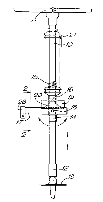
Figure 1 is a side elevation of a seat according to the present
invention,
Figure 2 is a section taken along the line 2-2 indicated on Figure 1,
and
Figure 3 is a partial side elevation showing the seat attached to a
golf cart or trolley.
The seat comprises a tubular stem member 10 which is preferably
formed of aluminium and which is provided at one end (the upper end) with a
seat structure 11 which is a folding structure similar to seat structures used
on so called shooting sticks and is provided at its other end (the lower end)
with a pointed foot member 12 having a pivoted plate number 13 which
again are similar to such members provided on the lower end of a shooting
.-~

1 2~R~
stick.
The stem member 10 extends through a tube 14 which is lined with a
plastics liner and is slideable in the tube 14. Extending between the tube 14
and the seat structure 11 is a coil spring 15 which surrounds the stem
member 10. The tube 14 is welded to a channel section bracket 16 which is
pivotally connected to a square section tubular mounting member 17 by a
bolt 18. It will be appreciated that the stem member 10 can be thus pivoted
about the axis of the bolt 18.
Secured to the bracket 16 is a substantially U-section member 19
which extends transversely of the tube 14 and which is located above the
mounting member 17. Extending between the member 19 and the mounting
member 17 is a flat spring 20 which in side elevation is of channel section.
The spring 20 applies a restoring force urging the stem member 10 to an
equilibrium or mean position if it is moved about the axis of the bolt 18.
The spring 15 is surrounded by a protective gaiter 21.
As will be seen from figure 3 the golf cart or trolley 22 is provided
with seat support structure which consists of a bracket 23 which is clamped
to a structural tube 24 of the cart or trolley 22 and a square section stem or
rod 25 on which the mounting member 17 can be slid. The mounting member
17 is retained on the stem a rod 25 by a fixing clip or clamp 26. It will be
appreciated that by releasing the clip or clamp 26 the seat can be
disengaged from the rod 25 and used independently of the cart or trolley 22.
In use the compression spring 15 moves the stem number 1û away
from the ground when the weight of the user is removed and the pivot action
of the stem member 10 allows the seat to be used on uneven ground, i.e. on
a slope.
.

Representative Drawing
A single figure which represents the drawing illustrating the invention.
Administrative Status

2024-08-01:As part of the Next Generation Patents (NGP) transition, the Canadian Patents Database (CPD) now contains a more detailed Event History, which replicates the Event Log of our new back-office solution.

Please note that "Inactive:" events refers to events no longer in use in our new back-office solution.

For a clearer understanding of the status of the application/patent presented on this page, the site Disclaimer , as well as the definitions for Patent , Event History , Maintenance Fee  and Payment History  should be consulted.

Event History

Description Date
Inactive: IPC deactivated 2015-03-14
Inactive: First IPC from PCS 2015-01-17
Inactive: IPC from PCS 2015-01-17
Inactive: IPC expired 2015-01-01
Inactive: IPC from MCD 2006-03-11
Inactive: Adhoc Request Documented 1994-10-01
Time Limit for Reversal Expired 1994-04-03
Letter Sent 1993-10-01
Grant by Issuance 1991-10-01

Abandonment History

There is no abandonment history.

Owners on Record

Note: Records showing the ownership history in alphabetical order.

Current Owners on Record
ACUSHNET LIMITED
Past Owners on Record
GEORGE P. POTTER
Past Owners that do not appear in the "Owners on Record" listing will appear in other documentation within the application.
Documents

To view selected files, please enter reCAPTCHA code :


To view images, click a link in the Document Description column. To download the documents, select one or more checkboxes in the first column and then click the "Download Selected in PDF format (Zip Archive)" or the "Download Selected as Single PDF" button.

List of published and non-published patent-specific documents on the CPD .

If you have any difficulty accessing content, you can call the Client Service Centre at 1-866-997-1936 or send them an e-mail at CIPO Client Service Centre.


Document
Description 
Date
(yyyy-mm-dd) 
Number of pages   Size of Image (KB) 
Cover Page 1993-10-22 1 12
Claims 1993-10-22 2 49
Abstract 1993-10-22 1 17
Drawings 1993-10-22 2 33
Descriptions 1993-10-22 2 69
Representative drawing 2000-07-27 1 12