Language selection

Search

Patent 1290057 Summary

Third-party information liability

Some of the information on this Web page has been provided by external sources. The Government of Canada is not responsible for the accuracy, reliability or currency of the information supplied by external sources. Users wishing to rely upon this information should consult directly with the source of the information. Content provided by external sources is not subject to official languages, privacy and accessibility requirements.

Claims and Abstract availability

Any discrepancies in the text and image of the Claims and Abstract are due to differing posting times. Text of the Claims and Abstract are posted:

  • At the time the application is open to public inspection;
  • At the time of issue of the patent (grant).
(12) Patent: (11) CA 1290057
(21) Application Number: 1290057
(54) English Title: METHOD AND APPARATUS FOR DISPLAYING MOVING OBJECTS
(54) French Title: METHODE ET APPAREIL D'AFFICHAGE D'OBJETS EN MOUVEMENT
Status: Expired and beyond the Period of Reversal
Bibliographic Data
(51) International Patent Classification (IPC):
  • G01S 7/48 (2006.01)
  • G01P 13/00 (2006.01)
  • G01S 3/781 (2006.01)
  • G01S 3/789 (2006.01)
(72) Inventors :
  • MENKE, JOSEF F. (Germany)
(73) Owners :
  • JOSEF F. MENKE
(71) Applicants :
(74) Agent: MARCUS & ASSOCIATES
(74) Associate agent:
(45) Issued: 1991-10-01
(22) Filed Date: 1988-08-30
Availability of licence: N/A
Dedicated to the Public: N/A
(25) Language of filing: English

Patent Cooperation Treaty (PCT): No

(30) Application Priority Data:
Application No. Country/Territory Date
P 37 29 059.2 (Germany) 1987-08-31

Abstracts

English Abstract


ABSTRACT OF THE DISCLOSURE
A method and apparatus are provided herein for displaying
moving objects. The method includes the steps of conducting a
line scan of an object with a prismatic rotating wheel, the
prismatic rotating wheel periphery including a plurality of
adjacent, recessed, and oppositely reflecting triplet mirror
surfaces. The prismatic wheel is rotated in order that
oppositely reflecting triplet mirror surfaces alternately
deflect a first signature scan and a second signature scan of
the object with a minimum mutual time shift in first and
second directions respectively, onto a single detector. The
first signature scan is time delayed by an intermediate
storage so that it is simultaneously available with the second
signature scan. The difference between the signature scans is
determined. Finally the remaining uncancelled individual
signals in the storage are defined as coordinates of the
object, and these coordinates are presented in electronic form
as output signals for defining position coordinates of the
object. The apparatus includes means for scanning and imaging
having a prismatic rotatable wheel for deflecting a first
signature scan and a second signature scan of an object with a
minimum mutual time shift, the prismatic rotatable wheel
periphery having a plurality of adjacent, recessed, and
oppositely reflecting triplet mirror surfaces which are
adapted to reflect the first and second signature scans in
first and second directions respectively; a single detector
for receiving the first and second signature scans having a
minimum mutual time shift; means for time delaying the first

Abstract of the Disclosure (continued page 2)
signature scan by an intermediate storage so that it is
simultaneously available with the signature scan; means for
determining the difference of the signature scans; and means
for defining the remaining uncancelled individual signals in
the storage as coordinates of the object and means for
presenting these coordinates in electronic form as output
signals for defining position coordinates of the object.


Claims

Note: Claims are shown in the official language in which they were submitted.

THE EMBODIMENTS OF THE INVENTION IN WHICH AN EXCLUSIVE
PROPERTY OR PRIVILEGE IS CLAIMED ARE DEFINED AS FOLLOWS:
1. A method for displaying moving objects comprising:
(a) conducting a line scan of an object with a prismatic
rotating wheel, said prismatic rotating wheel periphery
including a plurality of adjacent, recessed, and oppositely
reflecting triplet mirror surfaces;
(b) rotating said prismatic wheel in order that
oppositely reflecting triplet mirror surfaces alternately
deflect a first signature scan and a second signature scan of
said object with a minimum mutual time shift in first and
second directions respectively, onto a single detector;
(c) time delaying said first signature scan by an
intermediate storage so that it is simultaneously available
with said second signature scan;
(d) determining the difference between said signature
scans; and,
(e) defining the remaining uncancelled individual signals
in said storage as coordinates of said object, and presenting
said coordinates in electronic form as output signals for
defining position coordinates of said object.
2. The method of claim 1, wherein said minimum mutual
time shift is 50 ms.
3. An apparatus for displaying moving objects,
comprising:
(a) means for scanning and imaging having a prismatic
rotatable wheel for deflecting a first signature scan and a
second signature scan of an object with a minimum mutual time
-7-

shift, said prismatic rotatable wheel periphery having a
plurality of adjacent, recessed, and oppositely reflecting
triplet mirror surfaces which are adapted to reflect said
first and second signature scans in first and second
directions respectively;
(b) a single detector for receiving said first and
second signature scans having a minimum mutual time shift;
(c) means for time delaying said first signature scan by
an intermediate storage so that it is simultaneously available
with said signature scan;
(d) means for determining the difference of said
signature scans; and
(e) means for defining the remaining uncancelled
individual signals in said storage as coordinates of said
object, and means for presenting said coordinates in
electronic form as output signals for defining position
coordinates of said object.
4. The apparatus of claim 3, wherein said minimum mutual
time shift is 50 ms.
5. The apparatus of claim 4, wherein said prismatic
rotatable wheel has a periphery bearing adjacent, recessed and
mutually opposite triplet mirrors for reflecting said first
signature scan to one side and said second signature scan to
the other with rotation, whereby said second signature scan
has said mutual time shift from said first signature scan.
-8-

Description

Note: Descriptions are shown in the official language in which they were submitted.


~2~ 7
rl~ inverltion rela~es t~ light beam deflection
~y usiny a periodically moviny element and the present
invention is concerned with a method and apparatus for
displaying moving objects ttargets) whereby two time-shifted
o~ject signatures are imaged in dot-grid manner on a
detector.
In displays of this kind, the objects are irnaged in
the optical or infrared wavelength range on the detector
and tlle attempt is made to detect also small angular objects
Ear away.
Tlle state of the art of these displays may be
ascertained by reference to U.S. Patents 4,266,8~7;
~,57~,197; 9,5~,25~ and ~,733,072
In the present state oE the art these displays are
I implelnellted by carrying out parallel horizontal scanning in
all directions or over a large sector in one or more
superposed strips of a many elemen-t array. By comparing two
time-sequential scans, -the moving object may be recognized.
In such methodology, llowever, tllis comparison requires an
enormous memory. Moreover the repeat rate in such
procedures is in the seconds range. During that time period
! of seconds the object (target), when moving at so low an
angular speed as to be still significant, may have moved by
so many image dots, that it will be difficult to
unambiguously allocate the information of the two images.
-- 1 --
~'

- ~lZ9~(~57
-- 2
Angular speed herein means the speed of lateral deviation
of the moving object (target), for instance an incoming
rocket, from the line of sight between observer and rocket.
As a result, an object moving at high angular speed is of no
interest because it quickly passes by the observer, whereas
the object will be the more significant the less that angular
speed. When this angular speed is null, the object is moving
on a straight line directly toward the observer.
Objects of aspects of this invention are to provide a
method and apparatus which in the first place requires much
less memory and which in the second place allows a
substantially higher scan rate, whereby objects with only low
angular speed can also unambiguously be detected.
According to one aspect of the present invention a method
is provided for displaying moving objects comprising: (a)
conducting a line scan of an object with a prismatic rotating
wheel, the prismatic rotating wheel periphery including a
plurality of adjacent, recessed, and oppositely reflecting
triplet mirror surfaces; (b) rotating the prismatic wheel in
order that oppositely reflecting triplet mirror surfaces
alternataly deflect a first signature scan and a second
signature scan of the object with a minimum mutual time shift
in first and second directions respectively, onto a single
detector; (c) time delaying the first signature scan by an
intermediate storage so that it is simultaneously available
with the second signature scan; (d) determining the difference
between the signature scans; and, (e) defining the remaining

~2~ 57
-- 3 --
uncancelled individual signals in the storage as coordinates
of the object and presenting these coordinates in electronic
form as output signals for defining position coordinates of
the object.
The minimal mutual time shift is 50 ms.
By another aspect of this invention, apparatus is
provided for displaying moving objects, comprising: (a) means
for scanning and imaging having a prismatic rotatable wheel
for deflecting a first signature scan and a second signature
scan o~ an object with a minimum mutual time shift, the
prismatic rotatable wheel periphery having a plurality of
adjacent, recessed, and oppositely reflecting triplet mirror
surfaces which are adapted to reflect the first and second
signature scans in first and second directions respectively;
(b) a single detector for receiving the ~irst and second
signature scans having a minimum mutual time shift; (c) means
for time delaying the first signature scan by an intermediate
storage so that it is simultaneously available with the
signature scan; (d) means for determining the difference
between the signature scans; and (e3 means for defining the
remaining uncancell d individual signals in the storage as
coordinates of the object, and means for presenting these
coordinates in electronic form as output signals for defining
position coordinates of the object.
In such apparatus, the minimum mutual time shift is 50
ms.
In such apparatus, the prismatic rotatable wheel has a
periphery bearing adjacent, recessed and mutually opposite
~,

~9~305~
triplet mirrors for reflecting the first signature scan to one
side and the second signature scan to the other with rotation
whereby the second signature scan has the mutual time shift
from the first signature scan.
In the method and apparatus of the present invention for
determining object motion, only the coordinates of objects not
yet suppressed need be stored, and therefore the memory
capacity requirements therein are much less than in the state
of the art (omni-directional scanning), for instance by a
factor of 60. Simultaneously however, the scan repeat rate is
raised from the seconds range into a range of a scan rate
(frequency) of about 50 ms.
In the accompanying drawings,
Figure 1 is a schematic presentation of the problem;
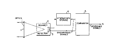
Figure 2 is a block diagram showing the apparatus for
carrying out the invention;
Figure 3 is a schematic representation of the common
imaging system of a rotating triplet reflecting wheel useful
in the line scan of scanner 2 of Figure 2;
: Figure 4 is a schematic representation showing how the
triplet reflecting wheel (mirrors) of Figure 3 reflect 50% of
an incident beam to one side and 50% to the other;
Figure 5 is a schematic representation of the triplet
mirror; and
~.'

~2~30(~7
Figure 6 is a detailed showing of the mirror of
Figure 5.
Figure 1 states tlle problem and this figure shows
target analysis using two air targets.
~ pproach ~ is a direct approach. When analyziny the
image coordinates oE two shifted object signatures, the
computer determines that while the coordinates are the same,
the signal amplitudes of the flying body have changed, i.e.,
they became larger because of the reduced distance.
Approach s is a pass. ~ shif-t results in the
pOsitioll of tlle target information of -the second scan
relative to the first scan. By taking the difference of the
two data a residual signal is o~Lained which is processed
further as a target signal by a guidance firing system.
I Figure 2 is a block diagram oE the apparatus with
wllicll tlle inventioll is carried out. The lens (optics) 1
transmits optical or infrared rays from a target to a
scanner 2 scanning tlle object field in a grid of lines and
columns. Illustratively the scanner described in the U.S.
Patent 4,266,847 is useful~ llowever a rotating triplet
reflecting wheel of the -type S]10WII in Figures 3-~ is used
for the line scan. This is a prismatic wheel of which the
periphery bears adjacent, recessed and mutually opposite
triplet mirrors. These -triplet mirrors reflect 50~ of an
incident beam -to one side and 50~ to the other (Figure 4)
, - 4 -

o~
when rotating the two reflected beams being relative shifted
to each other, namely by that time which is needed by one
triplet mirror to rotate from its first half to its second
half past the beam.
Accordingly the triplet mirror provides two beams of
the same image point which are slightly shifted from one
another and which are fed through other op-tical componen-ts
to a many-element detec-tor 3. Illustratively such a
! detector can be a Sprite detector with eight elements, which
is made by Mullard in Great Britain.
The outputs of the detector 3 therefore are the
signals of two time-shifted object signatures. The signals
of the first object signature are fed to a computer-
controlled electronic intermediate storage 4 and are stored
there until the signals of the time shifted second signature
are available.
The moment this is the case, the signals of the two
object signatures are simultaneously fed to a computer-
controlled, electronic comparator 5 where -their difference
is computed.
The remaining non-overlapping signals are due to the
target in sight which in the time interval between the first
and second object-field scans (time-shift between tlle two
I passes of the triple mirror halves at one beam~ aid move by
some distance.
These remaining signals 6 due to the target are fed
by the computer to a firing guidance sys-tem which determines
the target coordinates and issues corresponding firing
,commands.

~9~
The elec-tronic intermediate storage 4 and the
comparator 5 consist of conventional components, computers
etc. available to one skilled in the art.
' ~ - 6 -

Representative Drawing
A single figure which represents the drawing illustrating the invention.
Administrative Status

2024-08-01:As part of the Next Generation Patents (NGP) transition, the Canadian Patents Database (CPD) now contains a more detailed Event History, which replicates the Event Log of our new back-office solution.

Please note that "Inactive:" events refers to events no longer in use in our new back-office solution.

For a clearer understanding of the status of the application/patent presented on this page, the site Disclaimer , as well as the definitions for Patent , Event History , Maintenance Fee  and Payment History  should be consulted.

Event History

Description Date
Inactive: IPC from MCD 2006-03-11
Time Limit for Reversal Expired 1998-10-01
Letter Sent 1997-10-01
Grant by Issuance 1991-10-01

Abandonment History

There is no abandonment history.

Owners on Record

Note: Records showing the ownership history in alphabetical order.

Current Owners on Record
JOSEF F. MENKE
Past Owners on Record
None
Past Owners that do not appear in the "Owners on Record" listing will appear in other documentation within the application.
Documents

To view selected files, please enter reCAPTCHA code :


To view images, click a link in the Document Description column. To download the documents, select one or more checkboxes in the first column and then click the "Download Selected in PDF format (Zip Archive)" or the "Download Selected as Single PDF" button.

List of published and non-published patent-specific documents on the CPD .

If you have any difficulty accessing content, you can call the Client Service Centre at 1-866-997-1936 or send them an e-mail at CIPO Client Service Centre.


Document
Description 
Date
(yyyy-mm-dd) 
Number of pages   Size of Image (KB) 
Cover Page 1993-10-22 1 13
Abstract 1993-10-22 2 54
Claims 1993-10-22 2 66
Drawings 1993-10-22 3 40
Descriptions 1993-10-22 7 201
Representative drawing 2002-04-03 1 5
Maintenance Fee Notice 1997-10-29 1 178
Fees 1996-09-16 1 35
Fees 1995-09-01 1 37
Fees 1994-09-01 1 31
Fees 1993-08-25 1 38