Note: Descriptions are shown in the official language in which they were submitted.
1290318
PIPE BURSTER
The lnventlon relstes to plpe bursters for bursting gas malns, sewers,
water mains or other pipes.
It ls known to replace exlstlng plpe~, such as distribution mains for
natural gas made of cast iron or other metal, for example, by bursting
the plpe uslng a plpe burster and inserting a new pipe in the passage in
the ground formed by the burster. That technique i6 described for
example in British patent speclfications Serial Nos. 2092701A and
2169681A which also describe proposed examples of pipe bursters.
The bur~ter described ln British specificat~on Serial No. 216~681A comprises a
body in two parts which are relatively movable by a wedge which is moved
between the parts in the longitudinal direction of the burster by a
longitudinally extending hydraulic ram. In such a burster, the friction
ari4ing at the sllding surfaces of the wedge reduced the force avallable
for burstlng the main or other pipe. Also, the overall length of the
burster was increased by the length of the hydraulic cylinder beyond the
length of the two separable parts.
The ob~ect of the present lnventlon ls to provlde a burster ln whlch
those disadvantages are avolded.
A pipe burster accordlng to the lnventlon comprlses an elongated body in
two part~ extending in the lengthwise direction of the body, the two
parts being mutually guided by guide surfaces 80 as to be capable of
relative rectilinear separating and approach movements transversely to
rA ~
~Z903~8
ssld dlrectlon, hydraulic plston-and-cylinder means spaced apart along
the body being operable $n unison to effect at least said separating
movement.
Preferably, said piston-and-cylinder means comprise cylinders which are
in one of said parts and which contain respective pistons having
respective piston rods secured to the other of said parts, said guide
surfaces comprlsing concave cyllndrical surfaces on said one part and
respective convex cylindrical surfaces on said piston rods.
An embodiment of the lnvenelon wlll now be described by way of example
with reference to the accompanying drawings in which:-
Figures 1 and 2 are respectively a plan and a longitudinal verticalsection through the burster;
Figure 3 is a horizontal section on the line III-III in Figure 2;
Figure 4 i8 an ent elevation as seen in the direction of the arrow IV in
Figure 2;
Figures 5, 6, 7 and 8 are vertical sections on the lines V-V, VI-VI;
VII-VII; snd VIII-VIII, respectively, in Figure 2;
Figure 9 is an end elevation ~een in the direction of the arrow IX in
F$gure 2;
~2~0318
Flgures 10 and 11 are diagrams showlng a typlcal hydraullc circult and a
modlfled clrcuit, reRpect1vely, for use with the burster descrlbed with
reference to the preceding figures; and
Figure 12 1s a scrap section through the leading end of the burster shown
in Figures 1 ~ 2 showlng a feed hose-line at the leading end as a
modification.
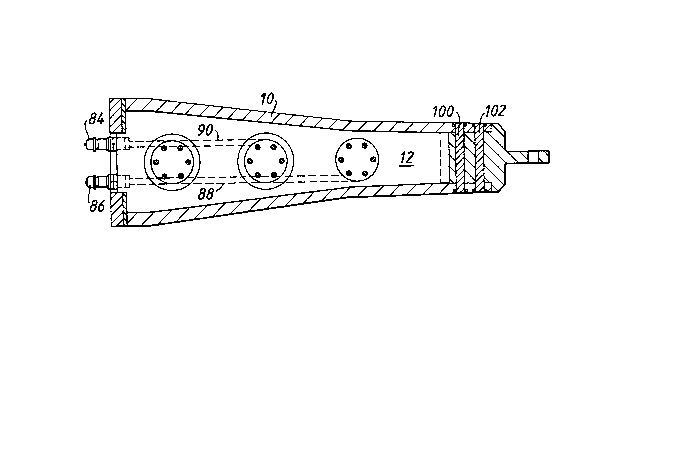
The burster shown in Figures 1 to 9 comprises two maln parts 10, 12 which
extend lengthwise of the burster. The part 10 is uppermost in the
burster in its position shown in the drawings 80 that the plan, Figure 1,
shows primarily the part 10. ~lgure 3 shows primarily the part 12 in
plan view and also shows the part 10 mainly in horizontal section.
The two parts 10, 12 are capable of relative separating and approach
movements rectillnearly trangver~ely to the length of the burster.
Separating movement is effected by three plston-and-cylinder means 14,
16, 18 (Figure 2). The three means 14, 16, 18 are spaced apart along the
length of the burster. Only the means 14, 16 are double-acting so that
~hey work in unison to effect relative approach movement of the parts 10,
12, the means 18 retracts idly during such movement.
The parts 10, 12 are, in this example of constructlon, steel castlngs and
the part 12 has machlned in lt the three cylinders of the means 14, 16,
18. The cylinders of the means 14, 16, 18 have respective piston6 20,
22, 24 having respective O-ring seals 26, 28, 30. In means 14 and 16 the
pistons 20, 22 are lntegral with respective plston rods 32, 34 of reduced
- 1290318 f`
-- 4 --
diameter so as to provide the double-acting capability. The piston 24 in
the means 18 is integral with a piston rod 36 of effectively the same
diameter as the piston. The diameters of the pistons 20, 22 are the same
(90 millimetres for example) whereas the diameter of the piston 24 is
slightly less (84 mm for example) because of the tapering shape of the
body (see Figure 7 for section through the means 18).
The piston rods 32 and 34 are engaged by respective 0-ring seals 40, 42
mounted in steel rings 44, 46 respectively located in countersunk
portions of the cylinders of the means 14 and 16. The piston rods 32 and
34 run through annular rubber shrouds 48, 50 located in the rings 44, 46
and the piston rod 36 runs through a shroud 52 located in a countersunk
portion of the cylinder of the mean~ 18.
The body 12 i8 effectively a cylinder block for the three means 14, 16,
18.
The three piston rods 32, 34, 36 are rigidly secured to the part 10 by
screws 54.
The parts 10, 12 are mutually guided for relative rectilinear movement by
the concave guide surfaces 58, 60 within the rings 44, 46 and the concave
guide surface 62 within the continuation of the cylinder of the means 18,
which surfaces slide again~t the convex outer surfaces of the
corresponding piston rods 32, 34 and 36, respectively.
12903~8
The relative approach movement of the parts 10, 12 is limited by
engagement of the inner curface 64 of the member 10 with the outer end
surfaces of the rings 44, 46 as shown in Figure 2. The separating
movement is limited by engagement of stop faces 66, 68 on the part 10
wlth respective stop faces 70, 72 on the part 12.
The rear end of the part 12 moves relatively to a hardened steel plate 74
on the part lO to lessen deleterious effects of fine soll particles
entering between the parts. A scraper seal 77 is provided in a groove in
the plate 74, and the rear end of the part 12 slides against the seal 77.
The two parts 10, 12 are otherwise mutually sealed by a seal 76 on the
part lO engaging the leadlng end of the part 12 (Figure 2) and by lateral
seals 78, 80 on the part 10 engaging the side6 of the part 12 (see
Figures 5 to ô).
The part 12 has st its rear end two couplings 84, 86 for hoses (not
~hown) which supply pressuri~ed fluid to and conduct fluid from the
piston-and-cylinder means 14, 16 and 18. The connector 84 communicates
~ia a passage 88 with the cylinders of the means 14, 16, 18 at the
undersides of the pistons 20, 22 and 24, so that pres6urised fluid can be
supplied to force the pistons outwardly to effect relative ~eparating
movement of the parts 10, 12. When the parts execute relatlve approach
movement, fluld ls expelled from the cyllnders at the underslde~ of the
piston6 and pas6es through the passage 88 to tank.
The coupllng 86 communicates via a pa~sage 90 with the cylinders of the
mean6 14, 16 at the top sldes of the piston6 20 and 22 so that
pressurlsed fluid can be supplied to force the pistons 20 and 22 lnwardly
~1
~2903i8
to effect relstlve approach movement of the parts 10, 12. When the parts
effect relative separating movement fluid is expelled from the cylinders
at the top sites of the pistons 20, 22 and passes to tank (see Flgures 10
and 11).
The part 10 is generally in the form of a channel (see Figures 5, 6, 7 &
8) and the part 12 is partly received within the part 10. The body made
up of the two parts 10, 12 tapers towards the leading end. The leading
end of the part 10 i8 connected by shear pins 100, 102 to a nose piece
104 provlding a leading lug 106 to whlch a hawser (not ~hown) can be
connected. ~ach part has an integral blade-like rib 108, 110 (Figures
7 and 8).
The plate 74 18 secured to the part 10 by 6crews 112 which also secure an
end member 114 of ~lmilar lnverted U-shape. Further screws 116 secure an
annular member 118 to the burster. A llner 120 of thin-walled
polyethylene, for example, can be clamped around or retalned withln the
member 118 and pulled lnto the burst main or other pipe to afford
protection against abrasion of the new replacement main of medium-density
polyethylene subsequently in~erted into the liner 120.
Flgures 2 and 4 show the parts 10, 12 in thelr relatlvely fully
approached position i.e. the minimum cro~s-section condition of the
burster. However, Figure 4 lndicates by broken line at 124 the maxlmum
cross-~ection of the burster at its rear end when the parts 10, 12 are
relatively at their fully separated condition.
A
~2903~8
As shown in Figure 4, the transverse cross-sectlonal shape of the two
parts 10, 12 making up the body of the ~urster is preferably such that
there are substantially corner-shaped shoulders at four locations 132,
134, 136, 138. Those locatlons correspond approximately to the positions
of corners of a notional rectangle. Such shoulders are present at least
where the burster is outside the unburst gas ~ain or other pipe indicated
approximately at 140 in Figure 2. Typically, in this example, the main
ls nominally a pipe having an internal diameter of 152 mm (6 inch main).
The burster can be inserted when the parts 10, 12 are in their fully
approached condition as shown ln Figure 2 until the end of the main
~assumed to be "~quare" l.e. ln an exactly normal transverse plane) ls
spproxlmately aligned with the centre of the pi~ton 24.
Flgure 10 shows the burster 150 with its couplings 84, 86 connected by
two high pressure llnes 152, 154 to a directlonal control valve 156 for
example of the type avallable from the Uandfluh company. The valve 156
receives pressurised hydraulic fluid from a pump 158 via a pilot relief
valve 160,a dump valve 162 and a filter 164. The pump 158 is driven by a
motor 166 and traws fluld from a reservoir tsnk 168 vla a stralner 170.
Excess fluld ls returned to the tank 168 from the dlrectional control
valve 156 via a cooler 172, which has an ln-line relief valve 174 in
parallel with it, and a low-pressure fl}ter 176.
Figure 11 shows a modified hydraulic circuit in which the same reference
numerals are used where appropriate. In this modificatlon, only one
external high pressure llne 152 18 used, connected to the coupling 84 of
A
2903~8 f`
the burster 150. The coupling 86 is connected via a line 180 to a
hydraulic accumulator 182, which acts like a return spring. The
accumulator is shown for clarity on an enlarged scale compared with the
burster 150 but in reality the accumulator is mounted on the rear end of
the burster 150 without greatly increasing its length. Typically the
accumulator 182 has a fluid capacity of about 1 litre. When the pistons
20, 22 are advanced they expel fluid via the passage 90 and the coupling
86 into the accumulator 182. The fluid entering the accumulator 182
compresses gas in the accumulator. When the directional valve 156
changes over, the stored gas pressure in the accumulator expels fluid at
relatlvely low pressure back into the cylinders of the means 14, 16 to
retract the pistons 20, 22 which retracts the part 10 together with the
piston 24. The use of only one pressure line 152 greatly improves the
handling of the burster 150 and its installation ln a pipe to be burst
because the line 152 is a flexible hose which has to be man-handled into
position and progressively fed into the pipe as the burster 150 advances.
The entrance to the pipe is in an excavation in the ground and the
hydraulic power pack comprising the components shown in Figure 11 is
positioned on the surface of the ground. The pressure line 152 extends
between the power pack and the burster 150 and may be some 50 metres or
more in length depending on the legnth of the pipe to be burst. The
normal working pressure of the fluid is set for example at 0.867 x 10⁷
newtons/square metre (3000 pounds/square inch) by the relief valve 160.
The pressure of the fluid delivered from the accumulator 182 is close to
the working pressure.
290318
If preferred, hydraulic fluid is fed to the burster via a hose-line or
lines through the leading end of the burster. The use o~ a single
hose-llne which is made possible preferably by an arrangement as shown in
Figure 11 is particularly suitable where it is preferred to supply the
fluid through the leading end of the burster. Figure 12 shows the
leading end of a burster with a single hose-line 200, which has the same
function as the line 152 in Figure 11, extending through a hole 202 at
the leading end wall 204 of the burster. The hose-line 200 is connected
to a coupling 204 through which fluid passes to a passage 206,
corresponding to the passage 88 shown in Figure 2. The hose-line 200 is
spooled on a drum (not shown) which hauls the attached to the lug 106.
The hose-line 200 is relatively heavy and operation using only a single
hose-line greatly reduces the handling difflculties by comparison with
the use of two hose-lines. The use of a single hose-line is at the
leadlng end particularly advantageous for example, where sewers are being
re-llned with short pipe lengths. Where the feed of fluid is to the
leading end of the burster the hose-line or lines must be fed through the
unburst pipe to the burster before bur~ting begins.
In modifications (not shown) the accumulator i8 connected to all of the
cylinders; or to at least one of them. The number of cylinders can be
other than three. The diameters of the cylinders can be identical. The
burster shown in Figures 1 to 9 is typically suitable for bursting 6-inch
(152 mm) gas distribution mains made of cast iron. When inserted fully
into such a pipe, with the two parts 10, 12 in their positions as shown
in Figure 2 fully approached towards one another, the external surfaces
of the burster engage the inner surface of the mouth of the pipe in the
transverse plane at the section line VII-VII shown in Figure 2.
1290318
-- 10 --
The transverse height of the burster at its rear end in that condition of
the parts 10, 12 is some 213 mm. The stroke of the relative movement of
the parts 10, 12 is typically 25 mm. Once the pipe has been burst, such
a burster typically pulls behind it into the burst and expanded pipe a
polyethylene liner of 200 mm outside diameter and wall thicklless 3 mm.
The replacement main is a medium-density polyethylene pipe of 180 mm
outside diameter.
Such a burster can burst pipes in the nominal range of 4 to 6 inches
(102-152 mm)~ It is possible to increase the effective overall diameter
of the burster by securing external shells to it, one on each part 10,
12. In this way the burster can be made to be effective in bursting
pipes up to 8 inches (204 mm) nominal diameter.
In larger sizes the burster is effective to burst even bigger pipes such
as for example sewer pipes of nominally 9 inches (22 cm) in diameter, the
outside diameter of the replacement pipe being up to 315 mm in that
case.
In a further modification (not shown) the relative approach movement of
the parts 10, 12 is effected by spring means e.g. one or more coil
springs arranged between the parts and stressed by relative separating
movement of the parts 10, 12.
DOC. NO. PAT2002