Note: Descriptions are shown in the official language in which they were submitted.
3~3~
PA-5345-0~ USA
w RE~ IOE:RATOR COP~PARl~B~IT ~ID ME~OD FOE~
ACCllRAl~LY CS ~aTROL~L113D TE:NP13RRTURl~ a
BA~ ~GROllND OF TEllE I~V~NTI~l~
o~ th~ Inv~ntion
The present invention relates generally to a
separate compartment and method in a combination
refrigerator-freezer having means for drawing cold air from
the freezer and mixing the cold air with compartment air for
circulation through the compartment.
DQscription of the Prior Art
A refrigerated compartment having a fan that draws
air from the compartment and mixes that air with air drawn
through a flue from the top of the freezer compartment is
disclosed in U.S. Patent No. 3,090,209. A thermostat is
included, located in the refrigerated compartment, to
control the operation of the fan.
U.S. Patent No. 3,659,429 discloses a fast chill
space in a refrigerator having an auxiliary timer controlled
fan adjacent an inlet passage from the freezer, which
passage includes a thermostatically controlled damper. The
inlet passage draws air from the top of the freezer adjacen~
evaporator openings from which cool air is discharged during
cooling cycles.
U.S. Patent No. 3,747,361 discloses a refrigerator
having a fast chill compartment similar to that disclosed in
the '429 patent which includes a switch for continuously
running the fan. In an alternate position, the switch
varies the fan operation dependent on the compartment
thermostat state.
3~34
PA-53~5-O-RE-USA
1 U.S. Patent No. 3,733,~41 discloses an air flow
control which mixes refrigerator compartment air with
freezer compartment air and utilizes a temperature sensor to
control operation of the compressor.
U.S. Patent No. 4,358,~32 discloses a fast chill
compartment which utilizes a microcomputer to control the
fan operation time.
U.S. Patent No. 3,122,005 discloses a refrigerator-
freezer combination having an evaporator in the divider wall
and a fan that draws air in through the side wall of one of
the compartments.
U.S. Patent No. 3,005,321 discloses a multiple
compartment refrigerator-freezer which utilizes two fans to
control the air flow and temperature.
SlJMMARY OF q~ PRESl~NT INVENTION
The present invention provides a device and method
for supplying cool, relatively constant temperature freezer
compartment air to a separate compartment to establish and
maintain an accurate temperature within the compartment.
The present invention also provides a device and method for
maintaining a low temperature gradient throughout a long-
term food storage compartment.
The present invention is embodied in a refrigerator-
freezer having a separate compartment maintained at an
accurate temperature, preferably near or just below the
freezing point of water, to provide a storage location for
long-term storage of perishable foods without freezing. The
compartment, known as a ~super cool" compartmentt includes a
cold air siphon to draw chilled air from near a mid-portion
29~38~
PA-5345~0-RE-USA
1 of the freezer compartment into a plenum chamber in the
controlled temperature compartment. The freezer air is
mixed in the plenum chamber with air from the super cool
compartment and circulated by a high capaci~y fan throughout
the compartment so that a low temperature gradient is
maintained across the entirety of the compartment.
The low compartmental temperature gradient and the
accurately controlled temperature of the present super cool
compartment enable foods to ~e stored for extended times
without risk of spoilage. The temperature can be set to and
maintained at a very precise point so that freezing is not
required. At lower temperatures, even longer storage can be
provided for foods that are less susceptible to chilling
injury.
BRIEF D~SCRIPTION OF T~E DR~WINGS
Figure 1 is a perspective view of a side-by-side
refrigerator-freezer, including an accurately controlled
temperature compartment according to the principles of the
present invention;
Figure 2 is a partial perspective view, in phantom,
of the refrigerator-freezer of Figure 1 showing an air flow
duct arrangement and fan housing for the compartment of the
present invention;
Figure 3 is a vertical cross-section along lines
III-III of Figure 2 showing additional details of the
present invention.
Figure 4 is a cross~section taken along lines IV-IV
of Figure 3 showing the freezer air siphon and plenum
chamber of the present invention;
" ~2~8~
PA~5345-O-RE-USA
1 Figure 5 is a horiæontal cross-section taken along
lines V-V of Figure 3 showing additional details of the
plenum chamber;
Figure 6 is a partial elevational view taken along
the lines VI-VI of Figure 4 and showing the relationship of
the freezer air siphon and the fan housing outlet; and
Figure 7 is a vertical cross-section of another
embodiment of the present invention having a controlled
temperature compartment below the refrigerator compartment
in a side-by-side refrigerator-freezer.
Figure 8 is a vertical cross-section of a further
embodiment of the present controlled temperature compartment
in a top-freezer type refrigerator-freezer.
Figure 9 is a cross-section along lines IX-IX of
Figure 8 showing the arrangement of the freezer air siphon
and return duct.
Figure 10 is a diagram of an electrical control
circuit as used in the present invention.
DESCRIPTION OF T~E PREFE~RED EMBODIMENTS
Figure 1 shows a side-by-side refrigerator-freezer,
generally at 10, including a cabinet 12 containing a
refrigerator compartment 14 having an openable door 16 and a
freezer compartment 18 having an openable door 20. A common
dividing wall 22 separates the refrigerator compartment 14
from the freezer compartment 18. A plurality of shelves 24
are mounted within both the refrigerator and freezer
compartments 14 and 18, as well as on the interior surfaces
of the doors 16 and 20. In the embodiment shown, a chilled
water and ice access panel 26 is provided at an exterior of
9~38~
P~-5345-O-RE-USA
1 the freezer door 20. A controlled temperature compartment
28 is provided above the refrigerator compartment 14 that
includes an interior door 30 which is accessible upon
opening of the refrigerator door 16.
In Figure 2, the controlled temperature, or super-
cool, compartment 28 is shown above the refrigerator
compartment 14 and beside the freezer compartment 18. A
plenum housing 32 having a shaped fan housing portion 34
within which is rotatably mounted a fan 36 is mounted on an
inside wall 38 of the super cool compartment 28. The plenum
32 includes air inlet slots 40 spaced from the fan hous-
ing 34. As the fan 36 operates, air is drawn from the
temperature controlled compartment 28, through the inlet
slots 40, and into a plenum chamber 42 in the interior of
the plenum 32.
A freezer air siphon, or dip tube, 44 is mounted
within the freezer compartment 18 and includes an upper end
46 in communication with the plenum chamber 42, as well as a
lower end 48 extending to near a mid-portion of the freezer
compartment 18. The lower end 48 has at least one freezer
air inlet 50 formed therein so that freezer air is drawn
from a mid-portion of the freezer compartment 18, along the
siphon 44, and into the plenum chamber 42.
A return duct 52 extends through the divider wall 22
between the controlled temperature compartment 28 and the
freezer compartment 18 through which air returns from the
compartment 28 to the freezer 18. A temperature selection
control 54 is provided on a front face portion 56 of the
plenum 32 by which the temperature within the controlled
temperature compartment 28 can be adjusted.
5_
~ 29t)~8a~
PA-5345-O~RE-USA
1 As shown by the arrows, the operation of the fan 36
creates an air flow from the fan housing 34 of the plenum 32
into and ~hroughout the interior of the controlled
temperature compartment 28. After circulation, a portion of
the air returns into the plenum chamber 42 at the air inlets
40 and is carried ~herethrough for recirculation by the fan
36. The operation of the fan 36 creates a low pressure ~one
within the plenum chamber 42 which causes air to be drawn
from the freezer compartment 18, into the siphon inlet 50,
upward through the freezer air siphon 44 and into the plenum
chamber 42, where it is mixed, or tempered, with the air
from the controlled temperature compartment 28 prior to
being exhausted by the fan 36. As air is removed from the
mid-portion of the freezer 18 by the siphon, or dip tube,
44, air within the controlled temperature compartment 28 is
returned to the freezer compartment 18 through the air
return duct 52. The present invention, thereby, mixes cool
freezer air with air circulating through the controlled
temperature compartment 28 to provide temperature regulation
of the air within the compartment 28.
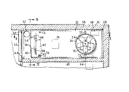
ReEerring to Figure 3, the controlled temperature,
or super cool, compartment 28 is partially enclosed by
insulated walls 58 of the cabinet 12, including a lower
insulated wall 60 between the compartment 28 and the
refrigerator 14. The door 30 completes the enclosure and is
mounted to the lower wall 60 by a hinge 62. A gasket 64 may
also be provided at the perimeter of the door 30 to ensure
an effective seal between the generally warmer refrigerator
compartment 14 and the super cool compartment 28.
--6--
9~
PA-5345-O-~E-US~
1 The temperature selection control 54, in the
embodiment shown, is a slide control projecting from the
face portion 56. The slide control 54 adjusts control
circuitry 66 contained within the plenum chamber 42.
Included in the control circuitry 66 and mounted just ~ithin
the plenum chamber 42 at the inlet openings 40 is a
temperature sensor 68. The temperature sensor 68 detects
temperature changes in the air flowing in through the inlet
slots 40 and, through the control circuitry 66, switches
into and out of operation a fan motor 70 which drives the
fan 36. The temperature sensor 68 is preferably mounted
close enough to the air slots ~0 to sense the ambient
temperature within ~he compartment 28 even when the fan 36
is not in operation. Inlet slots 40 are located in the
front portion of compartment 28 while fan 36 is located at
the rear portion of the compartment. This arrangement
assures adequate air flow and hence low temperature gra-
dients throughout the controlled temperature compartment.
The plenum housing 32 is mounted to the refriger-
ator-freezer divi.ding wal]. 22 by a plurality of screws 72
extending through sockets 74 in the plenum 32. Mounted
within the plenum chamber 42, in some embodiments, is a
heater 76. The heater 76 is controlled by the control
circuitry 66 to warm the air that was drawn into the plenum
chamber 42 by the fan 36 should the temperature within the
temperature controlled compartment 28 fall below the
predetermined set temperature set by the slide control 54.
A small dead band is built into the control circui~ry 66 so
that during heating the air temperature is heated to the set
12~ 8~
PA-53~5-O-RE-USA
1 temperature minus the dead band. It will be understood that
the set temperature can be fixed in some embodiment~.
The fan 36 is preferably of relatively large
capacity compared to the size of the compartment 28 so that
a high volume of air i5 circulated therethrough to maintain
an extremely low temperature gradient within the compartment
28.
The upper end 46 of freezer air siphon 44 is
generally at the same level as the air return duct 52.
Otherwise, there may be a tendency for a thermally induced
air flow between the freezer 18 and the super cool
compartment 28.
Figure 4 shows the freezer air siphon 44 extending
into the freezer compartment 18 to draw freezer air from
near a mid-portion thereof. Generally, cycling of the
evaporator, or cooling mechanism, shown at 78, in the
freezer compartment 18 causes temperature variations within
the freezer 18. The temperature variations are particularly
wide at the top of the freezer compartment 18 since cold air
is forced to the top of the freezer compartment 18 when the
cooling mechanism 78 is on and, when the cooling mechanism
78 is off, warmer air collects at the top of the freezer
compartment 18. Air below the top of the freezer compart-
ment 18 is less subject to temperature variations, and, in
particular, air near the mid-portion of the freezer is
relatively constant in temperature.
For purposes of the present invention, mid-portion,
or horizontal mid-portion, refers to that portion of the
freezer compartment spaced from the top and from the bottom
PA-534S-O-RE-~SA
1 of the freezer compartmant in which a lower temperature
variation occurs as the freezer cooling mechanism cycles.
In the embodiment shown, the air inlet 50 of the
freezer air siphon 44 is disposed jus~ above a shelf 24,
below which is an ice ma~er 80. In this portion of the
freeæer compartment 18, the temperature variations are
considerably reduced over that of the top of the freezer
compartment 18 and, therefore, a more controlled temperature
air is drawn into the plenum chamber 42 for mixing with the
air within the controlled temperature compartment 28.
Also referring to Figure 4, the slide control 54
includes a display 82 indicating the temperatures to which
the air temperature within the controlled temperature
compar~ment 28 may be set. The fan housing portion 34 can
be seen projecting beyond the body of the plenum 32 to more
effectively direct the air flow generated by the fan 36
throughout the compartment 28
Referring now to Figure 5, the freezer air siphon 44
is disposed at the rear of the freezer compartment 18 while
the air return 52 is at the front of the freezer compartment
18. A transverse cool air duck 34 at the top 46 of the
siphon 4~ extends through the wall 22 spaced somewhat
laterally and, as can be seen in Figures 3 and 6, above the
fan 36. Such arrangement provides for even distribution of
the controlled temperature air, as well as for some mixing
of the freezer air with the compartment air within the
plenum chamber 42 and for controlled return of the compart~
ment air to the freezer 18.
~.2~
PA-5345~0-RE-US~
1 In Figure 6, the relative sizes of th~ fan housing
34 and the transverse duct 84 of the freezer air siphon 44
are shown. The fan housing 34 is considerably larger than
the transverse duct 84 so that a relatively large quantity
of the temperature controlled compartment air is mixed with
a rela~ively small quantity of colder freezer air. The
siphon 44 i5 formed to accommodate the cooling mechanism 78
and to extend to just above the ice maker 80. The siphon 44
additionally prevents air from the cooling mechanism from
being forced into the transverse duct 84 when the fan 36 is
not operating.
In Figure 7 is shown a controlled temperature
compartment 100 disposed beneath a refrigerator compartment
102, which draws cool air from a freezer compartment 104
through a freezer air siphon 106 extending upwardly from
compartment 100 along the dîviding wall 108 and then
downwardly to near a mid-portion of the freezer compartment
104. An air return duct 110 is provided between the top of
the controlled temperature compartment 100 and the top of
the freezer compartment 104. The embodiment shown in Figure
7 includes many of the features of the above-discussed
embodiment, including drawing relatively constant tempera-
ture air from below the top of the freezer compartment
104. The freezer air siphon 106 and the return duct 110
both cross the adjoining wall 108 near the top thereof to
prevent thermally induced air flow. The freezer air siphon
106 is shown adjacent the ad]oining wall 108 while the
return duct 110 extends alongside the siphon 106 and spaced
from the wall 108 to prevent excessive warming of the
--10--
PA- 53 4 5-O-RE-USA
1 freezer air as it passes downward to the controlled
temperature chamber 100.
As shown in Figure 8, a controlled temperature
compartment 200 can also be provided in a refrigerator-
freezer 202 which has a freezer compartment 204 above a
refrigerator compartment 206. The refrigerator compartment
206 is separated from the freezer compartment 204 by a first
dividing wall 208, while the controlled temperature compart-
ment 200 is separated from the re~rigerator compartment 206
by a second dividing wall 210. A main door 212 is hingedly
mounted at the front of the refrigerator-freezer 202 for
access to the refrigerator compartment 206. An interior
freezer door 214 provides access to the freezer compartment
204, and an interior controlled temperature compartment door
216 provides access to the controlled temperature compart-
ment 200.
Within the controlled temperature compartment 200 is
a plenum housing 218 defining a plenum chamber 220, the
plenum housing 218 being provided with a fan housing portion
222 projecting therefrom. The p].enum housing 218 is mounted
on an insulated rear wall 22~ of the refrigerator-freezer
202. A freezer air siphon 226 is disposed in the insulated
rear wall 224 and has a lower end 228 in communication with
the plenum chamber 220. The freezer air siphon 226 extends
upwardly along the insulated rear wall 224 and has an upper
end 230 in communication with a horizontal mid-portion of
the freezer compartment 204.
An evaporator fan 232 is mounted in a divider 234
which separates an evaporator 236 from a main portion of the
~Z9~
PA-5345-O-RE USA
1 freezer compartment 20~. In the illustrated embodiment, the
upper end 230 of the freezer air siphon 226 is in communica~
tion with a suction side of the evaporator fan 232. This
prevents the evaporator fan 232 from forcing free7er air
down the freezer air siphon 226 to the controlled tempera-
ture compartment 200, and thereby prevents inaccurate
temperature sensing b~ a sensor (not shown) within the
plenum chamber 220.
Another view of the top-freezer type refri~era~or-
freezer unit 202 is shown in Figure 9~ The freezer air
siphon 226 extends to behind a fan 238 mounted within the
fan housing portion 222 of the plenum housing 218. In
communication with the controlled temperature compartment
200 and outside of the plenum housing 218 is a lower end 240
of a return duct 242~ The return duct 242, like the freezer
air siphon 226, extends vertically along the insulated rear
wall 224 and has an upper end 244 in communication with a
horizontal mid~portion of the freezer compartment 204. Like
the upper end 230 of the freezer air siphon 226, the upper
end 244 of the return duct 242 is on the suction side of the
evaporator fan 232. The upper end 244 of the return duct
242 is at a slightly higher elevation than the upper end 230
of the freezer air siphon 226. This prevents a reverse
thermal cycling of the freezer air which could cause
erroneous temperature sensing and control within the
controlled temperature compartment 200. The upper ends 244
and 230 could also be at the same horizontal level to
achieve this effect.
P~--5345-0-RE-USA
1The control circuit 66 is shown in Figure 10
including the slide control 54, the temperature sensor 6B,
the fan motor 70, and the heater element 76. An operational
amplifier 300 is provided in the control circuit 66 which
functions as a comparator and includes a positive feedback
loop 302 including a resistor 304. The provision of posi-
tive feedback in the comparator 300 causes the comparator toexhibit hysteresis.
A reference voltage is set at an inverting input 306
10of the comparator 300 by the slide control 54 which includes
a movable contact 308 for connection with one of a plurality
of pre-set resistance connections 310-318, as ~ell as an
open circuit connection 320 and a short circuit connection
322 to ground. The open circuit connection 320 corresponds
to a 20F voltage reference level at the inverting input 306
of the comparator 300. Each of the connection points 310-
318 have connected thereto resistors of respectively
decreasing resistance so as to provide voltage reference
levels in 2F increments. The short circuit connection 322
corresponds to an off-position of the slide control 54.
A non-inverting input 324 of the comparator 300 is
fed with an input voltage as determined by the temperature
sensor 68. Upon the input voltage at the non-inverting
input 324 reaching the reference voltage level at the
inverting input 306, the comparator 300 abruptly changes the
voltage at an output 326 which is fed to a first thyristor
328, shown as a triac~ The triac 328 controls the supply of
power to the fan motor 70.
~2~
PA-5345-O-RE-USA
1 A secon~ operational amplifier 330 also functions as
a comparator, however, without the provision of feedback. A
non-inverting input 332 of the comparator 330 is supplied
with the reference voltage level as established by the slide
control 54, while an inverting input 334 is supplied with an
input voltage as determined by the temperature sensor 68. A
voltage dividing resistor 336 maintains a voltage difference
between the input 324 of a first comparator 300 and the
input 334 of the second comparator 330, so that the second
comparator 330 is triggered at a lower temperature. The
resistor 336, thus, defines the dead band.
An output 338 of the comparator 330 is connected to
a gate 340 of a second thyristor 34~, also shown as a
triac. When the triac 342 is triggered by the comparator
330, power is supplied to the heater element 7~. The second
comparator 330 and second triac 342 can obviously be
eliminated from embodiments of the circuit 66 not requiring
a heater 76.
A zener diode 344 and capacitor 346 are provided in
the circuit 66 for power regulation.
The amplitude of the hysteresis provided by the
first comparator 300, in a preferred embodiment, is
approximately equal to loF. For instance, when the slide
control 54 is set at the 20 degree connection 320, the
comparator 300 triggers when the temperature sensor 68
senses a temperature of 20F, thereby starting the fan motor
70. The fan motor 70 continues to run until the comparator
300 is reset at approximately 19F, thereby preventing
extremely rapid cycling of the fan motor 70.
PA 5345-O-RE-USA
1 The present invention, thus, provides a means and
method for maintaining a compartment at a set temperature.
Cold freezer air is drawn from a central region oE a freezer
and is tempered by mixing with air already circulating
within the compartment.
In tests of the present device, the fan runs nearly
continuously, either at varying speeds or on a rapid duty
cycle. The resulting air circulation prevents air
stratification within the compartment.
The set temperature is maintained throughout the
compartment to within a fraction of a degree Fahrenheit.
Such accurate temperature control enables foods to be stored
for long periods, often without freezing injury. For
example, ground beef was stored at 23F in a frozen
condition for 51 days without detectable flavor loss. E'resh
~hellfish was stored in an unfrozen state at between 29 and
32F for three to seven days. And cherries were stored in a
non-frozen storage zone of 32-35F for 10 to 14 days
without spoilage or chilling injury.
Although the present invention is disclosed and
described in a combination refrigerator-freezer, it is
within the bounds of the present invention to provide a
controlled temperature compartment in conjunction with a
freezer unit.
Although modifications and changes may be suggested
by those skilled in the art, it is the intention of the
inventor to embody within the patent warranted hereon all
changes and modifications as reasonably and properly come
within the scope of his contribution to the art.
-15-