Note: Descriptions are shown in the official language in which they were submitted.
71
FLOWER POT
eAcKGRouND OF THE INVENTION
Overwatering has long been a problem in connect-ion
with potted plants. When excess water is introduced into the
pot containing a plant, the excess water is inclined to
accumulate adjacent the bottom of the pot and root rot or root
ball wetness may occur on the bottom of the root ball. Root
rot is affected by excess water.
GENERAL STATEMENT OF THE INVENTION
This invention relates to a pot fcr potted plants
wherein problems resulting from over watering are eliminated.
A porous block material insert bottom gives excellent
drainage capabilities, eliminates root rotting puddles of water
inside the pot and eliminates most negative results from
overwatering. The block material insert bottom gives excellent
anchorage, especially when used with a locating stake or
bracket.
A soil groove checking method is provided which gives
an accurate check of wetness on the bottom of a root ball as
soil on bottom of root ball and soil in the checking groove
will have approximately the same degree of wetness after a
short drainage period.
The combination of block material and a concrete
bottom insert prevents water from leeching upward from the
drainage tray, thus giving a more accurate check at the soil
groove. The bottom can also be made thinner, if desired, when
making larger pots, using a combination of materials.
A soil groove design in the form of a half circle is
preferable since there are no thin edges and it improves the
accuracy of the wetness check over previous designs.
A circle of lugs molded on the drainage tray allows
for firmer seating of the upper bottom insert when the shell of
1~905~
a pot is placed thereon. This also allows for some flexibility
in seating of the lower hal-f of the insert bottom. The lugs
also provide a space which allows for adequate ventilation and
flow passage around the bottom of the outer shell, preventing
water from becoming stagnant and preventing any unwanted odors.
The basic idea disclosed also applies to plan-ter
boxes as well as to flower pots.
With the above and other objects in view, the present
invention consists of the combination and arrangement of parts
hereinafter more fully described, illustrated in the
accompanying drawing and more particularly pointed out in the
appended claims, it being understood that changes may be made
in the form, size, proportions and minor details of
construction without departing from the spirit or sacrificing
any of the advantages of the invention.
BRIEF DESCRIPTION OF THE DRAWINGS
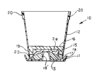
FIGURE 1 is a longitudinal cross-sectional view of
the complete assembly according to the invention;
FIGURE 2 is a longitudinal cross-sectional view of
the outer shell of the flower pot;
FIGURE 3 is a longitudinal cross-sectional view of
the outer shell of the flower pot with the upper block in
place;
FIGURE 4 is a longitudinal cross-sectional view of
the drainage tray, the upper insert and lower insert in place;
FIGURE 5 is a longitudinal cross-sectional view of
the drainage tray;
FIGURE 6 is a longitudinal cross-sectional view of
the upper insert and lower insert;
FIGURE 7 is a longitudinal cross-sectional view of
the lower insert;
1~9~57~
FIGURE 8 is a longitudinal cross-sectional view of
the upper insert;
FIGURE 9 is a long;tudinal cross-sectional view of
the upper block
FIGURE 10 is a top view of the drainage tray;
FIGURE 11 is a cross sectional view of the outer
shell cut from soil pipe with retainer required to hold the
upper half of bottom in place;
FIGUP~E 12 is a partial cross sectional view of the
drainage tray and outer shell of the flower pot;
FIGURE 13 is a side view of a support stake;
FIGURE 13A is a side view of the head of the stake
shown in Figure 13;
FIGURE 13B is a cross sectional view of the head of
the stake shown in Figure 13A;
FIGURE 14 is a longitudinal cross-sectional view of a
complete assembly of a planter and inserts according to the
invention,
FIGURE 15 is a longitudinal cross-sectional view of
the outer shell,
FIGURE 16 is a longitudinal cross-sectional view of
the drainage tray;
FIGURE 17 is a longitudinal cross-sectional view of
the lower insert and the upper insert;
FIGURE 18 is a top view of the upper insert as shown
in Figure 17;
FIGURE 19 is a side view of the top block;
FIGURE 20 is a top view of the top block;
FIGURE 21 is a partial longitudinal cross sectional
view of the of the shell and drainage tray; and,
FIGURE 22 is a top view of the drainage tray.
DETAILED DESCRIPTION OF THE DRAWINGS
1~90~
Now with more particular reference to the drawings, I
show a combination 10 of a drainage tray 11, an outer shell 12,
a lower insert 14 and an upper insert 15, and an upper block 16.
The drainage tray 11 has a float bottom 13 with upwardly and
outwardly extending side walls 18 and spaced upwardly extending
lugs 17 attached to the bottom 13. The lugs 17 are disposed in
a row equally spaced from the side walls 18. An upwardly
extending protrusion 18' is attached to bottom 13 at its center
and extends upwardly from the bottom 13 and is spaced
symmetrically from the upwardly extending side walls 18. The
protrusion 18' has a flat top 15.
Outer shell 12 is made of water impervious material
and is supported on lugs 17 and is generally cylindrical and
has a lower circular end 19 and an upper circular end 20. The
lower end 19 is substantially smaller than upper end 20. Lower
end 19 of shell 12 rests on lugs 17 whereby the first end of
the side wall is held in spaced relation to the bottom 13 and
provides a space for water to run under and for ventilation.
Lower insert 14 is made of concrete or similar block
material. Lower insert 14 has generally flat bottom 21 and
generally cylindrical side walls 22, frustoconical top 23 and
central bore 24. Central bore 24 is defined by a general
frustoconical surface. The flat bottom 21 of the lower insert
14 rests on the flat bottom 13 of the drainage tray 11. The
flat top of the protrusion of the drainage tray 11 extends
above the frustoconical top surface 23 of the lower insert 14
and into hole 27 in upper insert 15.
Upper insert 15 is made of a porous material having
the characteristic of cement cinder blocks. Upper insert 15
have a generally cylindrical outer periphery 26, generally flat
top surface side and a frustoconical central bore 27 and a
semi-circular groove 28 in the upper side 36. Upper block 16,
made of concrete, has an outer generally cylindrical peripheral
s~
surface 20 of slightly greater diameter than that of lower
insert 14, and a lower bore providing a downwardly extending
flange 29, which is disposed around upper insert 15 around the
outside of the soil groove 28. The upper block 16 has a flat
top surFace 35 on which soil can be supported.
Locating stake 40 has a ground insertable point 41
and a head 42 which is frustoconical in shape with a bore 32
and counterbore 32' for a screw head to secure the head 42 to
the point 41. Said stake 40 can be received in the
-Frustoconical recess in protrusion 18' to secure the device to
the ground.
The cylindrical outer shell 112 and retainer 135,
shown in Figure 11, can be substituted for the outer shell 12
of the other embodiments of the invention.
The flower pot can be assembled as in Figure 1, soil
put in groove 28 and the block 16 is put in place and potting
soil placed in outer shell 12. The plant can then be put in
place and normal watering commenced.
Now with more particular reference to the embodiment
of the invention shown in Figures 14 through 22, I show a
planter 110 having outer shell 113 which may be generally
rectangular in shape and a drainage tray 111. The drainage
tray 111 has a lower insert 114, an upper inset 115 and a top
block 116. The bottom of the drainage tray 111 has spaced
protrusions 118' extending upwardly from the bottom.
Protrusions 118' have an outer frustoconical surface and a top
125. Protrusions 118' extend through openings in the lower
insert 114 through openings in the upper insert 115. Upper
insert 115 has a soil groove 216. Drainage tray 111 has an
outer upwardly extending side walls 118. Upwardly extending
lugs 117 are attached to the bottom of drainage tray 111 and
are disposed in a row equally spaced from side walls 118. The
lower insert 114 is placed over the protrusions 118'. A soil
~90S7'~
groove 216 is formed around the inner periphery of the insert
of the upper insert 115. A top block 116 is supported over the
upper insert 115. Recesses 119 are formed in the upper and
lower inserts to receive protrusions 118'.
It will be noted that the porous block material lower
insert 114 provides excellent drainage capabilities and
prevents root rotting puddles of water and eliminates inside
rot, eliminating most negative results of overwatering. The
block material lower insert 114 gives an excellent anchorage.
The planter shown in Figures 12 through 22 can be used with
locating stakes 40, such as shown in Figures 13, 13A and 13B.
The stakes 40 may be driven into the ground and the head 42
with its frustoconical shape inserted into the protrusion 118'
which holds the assembly in place.
To check the soil moisture content of the device the
outer shell is raised up and separated from the tray to leave
the lower and upper inserts in the tray. The upper block
remains in the outer shell to hold the soil therein. The soil
groove in the upper insert is thereby exposed for checking the
moisture content. By checking the soil groove, an accurate
check of the root ball wetness on the bottom of the root ball
and soil on the bottom of the root ball above the block can be
made. A novel method is provided which is based on the
knowledge that a groove containing soil as set forth herein
will have approximately the same degree of wetness after a
short drainage period as said at the root ball. The concrete
block material gets its porosity and drainage capabilities from
a special block mixture. Water will not be seep up in large
enough quantities so as to be detrimental to the operation of
the device. Very little water will transfer from one insert to
another upward because of the break or seam between block
material inserts. The combination block material and cement
and the concrete bottom insert reduces water from leeching
S7~L
upward from the drainage tray and promotes water drainage, thus
giving a more accurate check at the soil groove. The lugs on
the bottom of the drainage tray allow for firmer seating of the
upper bottom insert when the shell of the pot is placed on it.
This also allows for some flexibility in seating of the lower
inserts bottom which it also allows for adequate ventilation
around the bottom of the outer shell preventing water from
being stagnated and from preventing any unwanted odor.
The foregoing specification sets forth the invention
in its preferred, practical forms but the structure shown is
capable of modification within a range of equivalents without
departing from the invention which is to be understood is
broadly novel as is commensurate with the appended claims.