Note: Descriptions are shown in the official language in which they were submitted.
Description
Reactant Distribution For Multi-Stack
Fuel Cell Power Plants
Technical Field
This invention relates to the fueling of fuel
cell stacks in multi-stack power plants, and more
particularly to a system whereby each cell in each
stack is assured an adequate fuel charge for proper
functioning.
Background Art
In order to enable the production of
commercially viable amounts of electricity from fuel
~ cells, the cells are arranged in stacks which
;; operate as a unit to provide the desired power. The
individual cells in the stack are generally flatly
configured and are coaxially stacked and connected
electrically in series with the electricity
generated flowing in the direction of the stack axis
through each cell in the stack, and thence into a
DC-to-AC converter. The hydrogen enriched fuel
which is used as a source of hydrogen ions and
electrons is fed through the individual cells in the
stack in a direction transverse to the axis of the
stack. Dissemination of the fuel to the cells in
~5 the stack is accomplished by means of inlet and
outlet manifolds which extend up opposite sides of
the stack and which are connected to fuel inlet and
outlet pipes.
C-1055
9~
For the stack to function properly, it is
essential that each fuel cell in the stack be
provided with sufficient fuel at least equivalent to
the current which is forced through it by operation
of the other cells in the stack. It is axiomatic
that uniform fuel supply problems to each cell will
intensify, the greater the number of cells in the
stack. Due to variations in dimensional tolerances,
the fuel flow will vary to each cell in the stack.
It is likewise axiomatic that the more fuel cells a
stack contains, the more electricity it will
produce. Thus a considerable problem of adequate
distribution of fuel can arise with a stack which
contains, for example, five hundred fuel cells in
it, which is a reasonable number of cells for a
commercially viable stack to have.
For efficient operation of a stack, the cells
~ should consume from 80 to 90% or more of the fuel
; supplied to them. Thus, by way of illustration, if
one hundred moles of fuel is supplied to a stack,
ideally 80 to 90 moles should be consumed by the
stack 10aving 10 to 20 moles of fuel to be exhausted
from the stack. In the event that due to
dimensional tolerances some of the cells will
receive more than their desirable mole share, then
less available fuel is left for the other cells in
the stack. Should a cell in the stack consume all
of the fuel available to it because of inadequate
fuel sup~ly caused by other cells receiving more
than their share, then that cell can go to a
negative state. This is due to a lack of hydrogen
atoms resulting from the lack of available fuel for
~9{~
the oxidation reaction. Such a ne~ative state cell
will consume or corrode the materials of the cell
; and fail in a short period of time, thus causing
failure of the stack.
The aforesaid fuel starvation and stack failure
problem is magnified manyfold in the case of power
utility size operations which produce megawatts of
power and require concurrent operation of many
stacks to produce such quantities of power. In the
; 10 prior art, the feeding of the fuel to a multi-stack
power plant has been accomplished in parallel
fashion. For example, if the power plant has three
stacks, each of which can utilize 100 moles of fuel,
and each of which is to run at a 90~ utilization
rate, then 300 moles of fuel are needed to run the
plant. The 300 moles of fuel are divided equally
and fed in parallel fashion, 100 moles to each
stack. With 90~ utilization, each stack will
produce a 10 mole depleted fuel exhaust. Thus each
stack will only have a 10 mole cushion to ensure
against individual cell fuel starvation, and
potential stack failure.
Disclosure of Invention
The distribution system of this invention
utilizes the same starting amount of fuel, operates
the stacks at the same utiliza~ion rate, and
produces the same depleted -Euel concentration for
the power plant as the aEoresaid prior art, but
ensures that there will be no chance for fuel cell
failure due to Euel starvation. Using the
distribution system of this invention, an individual
~Z90~3~3
stack will never be required to utilize more than
the overall percent of the fuel utilized by the
system, thus there will always be at least an excess
fuel cushion to ensure that individual cell fuel
starvation failure will not occur. In order to
achieve the aforesaid result, the fuel is fed to the
stacks at least partially in serial fashion, with
the depleted fuel exhaust from one or more stacks
being used as the fuel supply for one or more
subsequent stacks in the system. The stacks can be
fed in pure serial fashion one after another, or
they can be fed in stages, partly in parallel
fashion, and partly in serial fashion. In the
latter format, less than all of the stacks will be
initially fed equal proportions of the total fuel
needed, and the partially depleted fuel exhausted by
them will be combined and fed into one or more
subsequent stacks. The partially depleted fuel
exhausted by the initial stack or stacks in the
series is fed directly into the subsequent stack or
stacks in the series without any enrichment other
than combining with other stack exhausts, if
present.
It is, therefore, an object of this invention
to provide a system for fueling multiple fuel cell
stacks in a power plant which ensures that each cell
in the plant will receive adequate fuel for proper
eunctioning.
It is a further object of this invention to
provide a system of the character described wherein
an increased excess fuel cushion is provided to
-- 5
ensure that no cell will experience fuel starvation
due to excessive consumption of fuel by other cells in
the stack.
It is yet another object of this invention to
provide a system of the character described which
utilizes the depleted exhaust fuel from one or more
stacks as fuel for subsequent stacks.
It is an additional object of this invention to
provide a system of the character described wherein
fuel is fed serially through successive stacks in the
power plant.
It is another object of this invention to
:provide a system of the character described wherein
fuel is fed in parallel and serial fashion through
stacks in the power plant.
It is yet an additional object of this invention
to provide a system of the character described wherein
the cell components can be made more economically due
to relaxation of dimensional tolerances which results
from utilization of the system.
In accordance with a particular embodiment of
the invention, there is provided, in a multi-stack
fuel cel.l power plant, a fueling system comprising:
a) a first power-generating stage including one or
more identical fuel cell stacks;
b) a second power-generating stage including one or
more fuel cell stacks, the stacks in the second stage
being identical to the stacks in -the first stage;
c) means providing an amount of fuel to said system
sufficient to operate all of the stacks in the system
a-t a predetermined identical fuel. utiliza-tion rate;
d) means for delivering all of said amount of fuel
to said first stage for operation of the latter; and
~290803
- 5a -
e) means for delivering all of the fuel exhausted
from said first stage to said second stage for
operation of the latter, said fuel exhausted from said
first stage always comprising more fuel than is
necessary to operate said second stage at said
predetermined fuel utilization rate.
In accordance with a further embodiment of the
invention, -there is provided, in a multi-stack fuel
cell power plant, where all of the stacks are
identical to each other, a fueling system comprising:
a) a first power generating s-tage including one or
more fuel cell skacks;
b) a second power generating stage including one or
more fuel cell stacks;
c) means providing an amount of fuel to said system
suffi.cient to operate each of the stacks in the system
with a predetermined identical aliquot of said amount
of fuel;
d) means for delivering all of said amount of fuel
to said first stage for operation of the latteri and
e) means for delivering all of the fuel exhausted
from said first stage to said second stage :for
operation of the latter, said fuel exhausted from said
first stage always comprising more fuel than the sum
of said fuel aliquots for each stack in said second
stage whereby each stack in said second s-tage is
protected against shutdown due to fuel starvation of
its individual fuel cells.
In accordance with a further embodiment of the
invention, there is provided, in a multi-stack fuel
cell power plant wherein all of -the stacks are
identical, a fueling system comprising:
a) a first power generating stage containing a
pluralit.y of stacks constituting all of the stacks in
the power plant except one;
,,:
~ Z908~
- 5b -
b) a second power generating stage containing the
remaining stack;
c) means providing an amount of fuel for said
system sufficient to operate each of the stacks in the
system with an identical predetermined aliquot of
fuel;
d) means for delivering all of said amount of fuel
in equal shares, each of which is larger than said
predetermined aliquot, to each of said stacks to said
first stage;
e) exhaust conduit means interconnecting said
stacks in said first stage with said stack in said
second stage, said exhaust conduit means being
operable to combine all of the fuel exhausted from
said stacks in said first stage and deliver said
combined fuel to the stack in said second stage in an
amount which is larger than said predetermined aliquot
of fuel whereby each stack in the system always
operates with a supply of fuel which is larger than
said predetermined aliquot.
In accordance with a further embodiment of the
invention, there is provided, a multi-stack fuel cell
power plant comprising:
a) a series of fuel cell stacks having an initial
stack, one or more medial stacks and a final stack;
b) means providing an amount of fuel to said series
of stacks sufficient to operate each of the stacks in
the series with a predetermined identical aliquot of
said amount of fuel;
c) means for feeding all of said amount of fuel to
said initial stack;
d) means for feeding all of the fuel exhaust from
said initial stack to one of said medial stacks and
for feeding seriatim all of the fuel exhaust from one
-` ~L2~
- 5c
stack to another stack whereby each stack, save said
initial stack, is fueled solely by exhaust from a
preceding stack; and
e) wherein the exhaust from each stack, save said
final stack, contains more fuel than said predeter-
mined aliquot whereby each stack in the series always
operates with a supply of fuel which is larger than
said predetermined identical aliquot.
From a different aspect, and in accordance with
the invention, there is provided a method of fueling a
multi-st~ck fuel cell power plant, said method
comprising the steps of:
a) providing a supply of fuel sufficient to furnish
each stack in the plant with a predetermined identical
aliquot of operating fuel;
b) feeding all of said supply of fuel into a first
stage of the plant, which first stage includes one or
more stacks; and
c) feeding all of the exhaust fuel from said first
stage into a second stage of the plant, which second
stage includes one or more stacks whereby each stack
in the plant is always supplied with an amount of
operating fuel which is greater than said predeter-
mined aliquot.
In accordance with a further embodiment, there
is provided a method of fueling a two-stage multi-
stack fuel cell power system having a plurality of
fuel cell stacks, said method comprising the steps of
feeding a first stage containing a plurality of stacks
constituting all of the stacks but one in the system
with a parallel fuel feed arrangement whereby each of
the stacks in the first stage receives an equal share
of the fuel needed to operate the entire system at a
predetermined ident:Lcal fuel utilization rate, and
combining all of the fuel exhausted from the stacks in
"
.'
;.
~908~3
- 5d -
the first stage and fueling the remaining stack in the
system with the combined exhaust fuel from the first
stage, the combined exhaust fuel constituting more
than enough fuel to operate the remaining stack at the
predetermined fuel utilization rate.
In accordance with a further embodiment, there
is provided a method of fueling a multi-stack fuel
cell power system having a plurality of fuel cell
stacks arranged in series to define a last stack in
the series, comprising the steps of feeding fuel to
the stacks in the system serially wherein all of the
fuel exhausted from some of the stacks is used to fuel
others of the stacks subsequen-t in the series, and
providing an amount of fuel to the last stack whereby
the fuel utilization rate of the last stack is defined
by the formula
UL overall/Uoverall + N(100-u 11)
wherein UL is the percent of fuel utilized by the last
stack, U 11 is the percent of fuel utilized by the
entire system, and N is the number of stacks in the
system.
These and other objects and advantages of the
invention will become more readily apparent from the
following detailed description of preferred embodi-
ments thereof when taken in conjunction with the
accompanying drawings in which:
Brief Description of Drawings
FIGURE 1 is a schematic block diagram illus-
trating the prior art. system for feeding fuel to a
multi-stack power plant;
..... .... .
~L2~8~3
- 6 -
FIGURE 2 is a block diagram similar to FIGURE 1
but showing a first preferred embodiment of a fuel
feeding system for a multi-stack power plant which
operates in accordance with this invention; and -
FIGURE 3 is a block diagram similar to FIGURE 2
but showing a second embodiment of a feeding system
operating in accordance with this invention.
Best Mode for Carrying Out the Invention
Referring now to FIGURE 1, there is shown in
block diagram form a fuel feeding system for a
multi-stack power plant which operates in accordance
with the teachings of the prior art. The plant
shown has a plurality of stacks as, for example,
three. ~ach stack is allotted enough fuel so that
it can operate at maximum efficiency by consuming
90% of that fuel allocation, or aliquot. For
purposes of illustration, assume that each stack is
; allocated 100 moles of fuel and that it will utilize
or consume 90 moles (90%) of that allocation. The
total fuel thus fed into the three stacks shown
would be 300 moles which is fed through the conduit
2. The 300 moles of fuel is divided into equal 100
mole portions which are fed individually into STACK
~; 1, STACK 2, and STACK 3 via branch conduits 4, 6 and
8 respectively. With each stack utilizing 90~ of
its fuel allocation, 10 moles of fuel will be
exhausted from each stack throu~h exhaust conduits
10, 12. and 14. Thus the total fuel input is 300
moles, the total fuel consumption is 270 moles, and
the total fuel exhausted is 30 moles, assuming a 90g
utilization rate. Obviously, the consumption and
~L~90803
exhaust figures will vary should the consumption
rate be changed. With the parallel feed system,
each stack has only a lO mole cushion to use to
guard against individual cell fuel starvation in the
event of excessive percent fuel consumption due to
low flow of fuel to one or more cells in a stack.
This cushion could be increased by increasing the
fuel allocated to each stack, however, such an
approach would be wasteful of the fuel. In order to
minimize the occurrence of cell fuel starvation when
operating with such a small excess fuel cushionv
cell and stack component specification tolerances
become so tight that commercial im~racticality o~
the power plant concept is markedly increased. It
will be noted in FIGURE l that there may be other
stacks in the system which will be fueled in a
similar manner. It is understood that the 300 moles
of fuel referred to above is merely the aliquot of
the total fuel which is allotted to the stacks
actually shown.
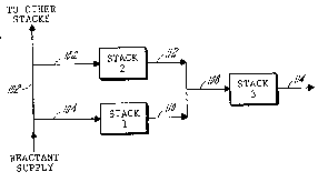
Referring now to FIGURE 2, there is shown a
preferred fuel distribution system eor three stacks
which operates in accordance with this invention.
The allotted three stacks aliquot of 300 moles of
fuel is delivered to the stacks via the conduit 102.
The 300 moles of fuel is divided into equal 150 mole
sharesl one of which is ~ed into STACK 1 through
conduit 104 and the other of which is fed into ST~CK
2 through conduit 106. STACK l and STACK 2 operate
at the 90 moles fuel consumption rate and thus each
will consume about 90 moles of the 150 moles Eed
into it. Thus each stack will exhaust 60 moles into
~ 29~l303
the exhaust conduits 110 and 112. This means that
the fuel starvation cushion for each o~ STACK 1 and
STACK 2 is 60 moles. STACK 1 and STACK 2, using the
system shown in FIGURE 2 with the preferred 90 mole
consumption rates will consume only 60~ of the fuel
fed into each of them. The two 60 mole exhausts
from STACK 1 and STACK 2 are then combined in ~ ;
conduit 108 so that STACR 3 is fed 120 moles of
fuel. STACK 3 operates at its pre~erred 90 mole
consumption level thus consuming 90 of the 120 moles
of fuel and exhausts the remaining 30 moles of fuel
through conduit 114. Thus STACK 3 has a 30 mole
fuel starvation cushion when operating at its
preferred consumption level. It will be noted that
STACK 3 will thus consume only 75% of the fuel fed
into it. The system shown in FIGURE 2 thus feeds
the same initial total fuel into the three stack
power source, i.e. 300 moles, as that shown in
FIGURE 1, but in the FIGURE 2 system, each stack is
provided with a much greater fuel starvation cushion
during operation. This additional leeway is
provided merely by properly arranging the feeding
sequence and does not require any additional fuel
enrichment anywhere in the system. With the
additional fuel cushion provided by this system,
manufacturing tolerances are significantly relaxed
so that the concept of a multi-stack commercial
utility power source becomes commercially viable.
Dimensional tolerances do not need to be severe to
ensure that all cells in the stack receive their
re~uired share of the total fuel available using the
system of FIGURE 2 since during the feeding of each
.~ ~
. .
1.290~3~33
g
stack, there is ample extra fuel available to
accommodate some cells using more than their ideal
share. It will likewise be appreciated that
additional stacks can be fed in a like manner. For `
example, a six stack power plant can be fed in a
five to one parallel serial system, or, less
preferred, in a three, two, one parallel serial
system. It will be noted that the essence of the
system shown in FIGURE 2 is that the exhausted fuel
from all stacks except the terminal stack or stacks
adds to the fuel cushion available for any
subsequent stacks. Such is not the case for the
prior art system shown in FIGURE 1.
It will be appreciated that the system of this
invention facilitates the fabrication of stacks in
modular building block-type units which can be used
to construct large multi-stack plants. When a
system of stacks is fueled using this system, the
percent of the fuel utilized by the last stack in
the system will always be less than the overall
utilization of the system, and can be calculated by
the formula:
L overall/Uoverall + N(l~Uove 11)
wherein UL is the percent of Euel utilized by the
last stack in the system~ UOverall is p
fuel utilized by the total system and N is the
number of stacks in the system.
Referring now to FIGURE 3, there is shown a
second embodiment of the invention wherein the
stacks are fed in Purely serial Eashion. The
conduit 202 carries the requisite 300 moles of fuel,
~2~)803
-- 10 --
all of which is fed into STACK l via conduit 204.
STACK 1 consumes its 90 mole portion of the fuel and
exhausts 210 moles into STACK 2 through conduit 206.
STACK 2 then consumes its 90 mole share of the 210
moles and exhausts 120 moles into STACK 3 through
conduit 208. STACK 3 consumes its 90 mole share and
exhausts 30 moles of the fuel through conduit 214.
With the system shown in FIGURE 3, STACK l consumes
30% of the fuel fed into it, STACK 2 consumes 42.8~ ;
of the fuel fed into it, and STACK 3 consumes 75% of
the fuel fed into it. As in each of the foregoing
examples, the total fuel fed into the system is 300
moles and the total fuel exhausted from the system
is 30 moles. The system shown in FIGURE 3, like
that shown in FIGURE 2, allows fabrication of stack
components with more relaxed dimensional tolerances
due to the increased fuel cushion and thus is viable
for use in a multi-stack commercial utility power
plant.
; 20 The embodiment shown in FIGURE 2 is preferred
over the embodiment of FIGURE 3 due to the fact that
the former has ~ewer stages and thus requires less
pressure to pump the fuel through the system, or for
the same inlet pressure, results in lower pressure
loss.
It will be readily appreciated that the system
of this invention will greatly minimize or eliminate
Euel cell stack failure in multi~stack power plants
due to individual cell fuel starvation. The system
provides these advantages without the need to
increase fuel input or exhaust. Use of the system
renders practical, commercial utility sized
,. .- .~
~ ~9()803
multi-stack power plants due to relaxation of
manufacturing tolerances. The oxygen can be fed
into the stacks serially or in parallel fashion.
Since many changes and variations of the
S disclosed embodiments of the invention may be made
without departing from the inventive concept, it is
not intended to limit the invention otherwise than
as required by the appended claims.