Language selection

Search

Patent 1291049 Summary

Third-party information liability

Some of the information on this Web page has been provided by external sources. The Government of Canada is not responsible for the accuracy, reliability or currency of the information supplied by external sources. Users wishing to rely upon this information should consult directly with the source of the information. Content provided by external sources is not subject to official languages, privacy and accessibility requirements.

Claims and Abstract availability

Any discrepancies in the text and image of the Claims and Abstract are due to differing posting times. Text of the Claims and Abstract are posted:

  • At the time the application is open to public inspection;
  • At the time of issue of the patent (grant).
(12) Patent: (11) CA 1291049
(21) Application Number: 1291049
(54) English Title: ACTUATING DEVICE FOR A VEHICLE BRAKE RIGGING
(54) French Title: DISPOSITIF DE COMMANDE POUR MECANISME DE FREIN
Status: Expired and beyond the Period of Reversal
Bibliographic Data
(51) International Patent Classification (IPC):
  • F16D 65/28 (2006.01)
  • B60T 17/08 (2006.01)
(72) Inventors :
  • ROGER, MICHEL (France)
(73) Owners :
  • SAB WABCO SA
(71) Applicants :
  • SAB WABCO SA (France)
(74) Agent: SMART & BIGGAR LP
(74) Associate agent:
(45) Issued: 1991-10-22
(22) Filed Date: 1986-03-04
Availability of licence: N/A
Dedicated to the Public: N/A
(25) Language of filing: English

Patent Cooperation Treaty (PCT): No

(30) Application Priority Data:
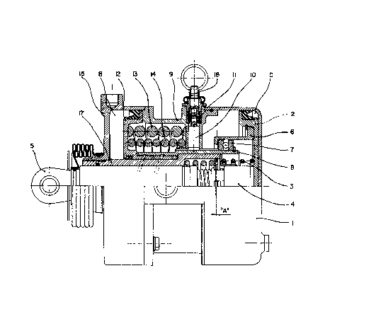
Application No. Country/Territory Date
85 03419 (France) 1985-03-08

Abstracts

English Abstract


ABSTRACT
An actuating device for a vehicle brake rigging, comprising a service
brake and a spring parking brake.
The device comprises, apart from a service brake cylinder (1) and piston
(2) and a parking brake cylinder (15, 17) and piston (12), a ratchet wheel (8)
disposed between the two pistons, non-permanent connection means (6, 7)
provided between the ratchet wheel and the service brake piston; and further
connection means (10, 12) provided between the ratchet wheel and the
parking brake piston; the ratchet wheel being controllable in translation and
in rotation-translation, depending on whether a chamber (B) of the parking
brake cylinder is either emptied or fed.


Claims

Note: Claims are shown in the official language in which they were submitted.


The embodiments of the invention in which an exclusive
property or privilege is claimed are defined as follows:
1. An actuating device for a vehicle brake rigging, comprising:
- a service brake actuator including a service brake
cylinder, a service brake piston slidingly mounted therein and
a push rod mounted to said piston for movement therewith;
- a spring parking brake actuator mounted in front of said
service brake actuator and extending around said push rod, said
spring parking brake actuator comprising a parking brake
cylinder, a parking brake piston slidingly mounted therein and
spring means for acting on said parking brake piston to move same
in said parking brake cylinder, said parking brake piston being
solely in a pull force transmitting relationship with said
service brake piston by means of a generally cylindrical
rotatable ratchet wheel engaged at one end with said parking
brake piston by helical ramp means between cylindrical surfaces
and rotatably engaged at an opposite end with said service brake
piston, and pawl means spring biased toward said ratchet wheel
to engage with said same for preventing rotation thereof, said
pawl means being manually movable out of engagement with said
ratchet wheel
2. An actuating device as defined in claim 1, comprising a ball
bearing between said ratchet wheel and said service brake piston.
-4-

Description

Note: Descriptions are shown in the official language in which they were submitted.


A~ ACTUATING DEVICE FOR A V~ICLE BRA~E RI~GIMG
Technical E'ield
This invention relates to an actuating device for a vehicle
brake rigging, comprising a service brake and a spring parking
brake. The invention applies more particularly but not
exclusively to brake riggins for railway vehicles.
Bac~ground of the Invention
~ device of this kind has the object of applying a brake
force either by supplying pressurized fluid to the service brake
or by holding the parking brake applied by its springs, when the
fluid pressure in the vehicle has decreased inadvertently through
exhaust (leak) or wilfully by remote control from the driver's
cab (electric valve). Such device can moreover be manually
deactivated to permit the vehicle to be driven in the absence of
pressure and automatically reactivated as soon as the pressure
has increased when the vehicle has been brought into operation
again. This last manipulatlon can be effected where it is
desired to neutralize ~he parking brake while leavlng the service
brake usable following an incident such as breakage of a feed
hose.
Th~ Invention
In a broad aspect, the invention compri.ses an actuating
device for a vehicle brake rigging, comprising:
- a service brake a~tuator includiny a service brake
cylinder, a service brake piston slldinyly mounted therein and
a push rod mounted to the piston for movement therewith;
- a spring parking brake actuator mounted in front of the
service brake actuator and extending around the push rod, the
spriny parking brake actuator comprising a parking brake
cylindert a parking brake piston slidingly mounted therein and
spring means for acting on the parking brake piston to move same
in the parking brake cylinder, the parking brake pis~on being
solely in a pull force t~ansmitting relationship with the service
brake piston by means of a generally cylindrical rotatable
ratchet wheel engaged at one end with the parking brake piston

~2~
la
by helical ramp means between cylindrical surfaces and rokatably
engaged at an opposite end with the service brake piston, and
pawl means spring biased toward the ratchet wheel to engage with
same for preventing rotation thereof, the pawl means being
manually movable out of engagement with the ratchet wheel.
Preferably, the parking brake cylinder and the service brake
cylinder are placed in opposed relati.onship.
Brief Description of the Drawing
The invention will be described in further detail below
under reference to the accompanying drawing, which is a side~
view, partly in section, of a device according to the invention.

~29~
Description of a Pre~erred Embodimen~
A de~ice according to the in~ention comprises a ser~ice brake
cylinder 1, controlled by pressurized fluid, a piston 2, provided with a return
spring 3 and axi~lly mo~,able in the cylinder and connected to a slack adjus~er
5 4 which transmits a brake Eorce to a rod 5 (ended by an ear); a pulling slee~e6 secured to the ser~ice brake piston 2; an axial ball bearing 7 disposed on a
rotatable ratchet wheel 8, on the one hand pre~,ented from rotation relative
to a housing 9 by a pawl 10, normally held in engagement by a spring 11, and
on the other hand connected to a parking brake piston 12 ~ia a helical ramp
10thereon, the latter piston 12 mo~ing axially in a parking brake cylinder 15, 17
to the left in the drawing under the action of forceful springs 13 and 14, the
parking brake cylinder being disposed in an opposed relationship in respect to
the ser~,ice brake cylinder l; and a pulling means 16 Eor lifting up the
pawl 10.
15The parking bral<e cylinder is actually constituted by a cylinder 15
proper and a sleeve 17 that can be screwed or unscrewed in said cylinder
- thereby to increase or diminish a control distance "A" of the slack adjuster 4.
The operation is as ~ollows:
When the ser~ ice brake is released its piston 2 rests under the action oE
20 the spring 3 on the bottom of the cylinder 1 while maintaining a clearance
between the ball bearing 7 and the pulling sleeve 6.
At service brake application Eluid flows into a chamber C and pushes
the piston 2 as well as the rod 5 to the left in the drawing via the slack
adjuster 4, which is pro~ ided Eor maintaining the piston stroke and
consequently the
25 clearance or slack between the brake shoe or block and wheel or dislc
constant independently oE the wear.
When the ~ehicle runs the parking brake is in the released brake
position, i.e. the pressurized fluid in chamber B maintains the springs 13 and
14 compressed through the piston 12, itself supported by the housing 9 and
30 the ratchet wheel 8, such that there is pro~ided a clearance between the ball bearing 7 and the pulling slee~e 6.
Upon parking, when fluid pressure disappears in the chamber B, the
piston 12 mo~es forward (to the le~t in the drawing) under the action oE
springs 13 and 14 thereby pulling also the ratchet wheel 8, which is non-
35 rotationally connected to the piston 12 through the pawl lO. Consequently theball bearing 7 pulls the ser~ ice brake piston 2 ~ia the pulling slee~e 6

` ~l293L()~9
thereby transmitting the ~orce o~ the springs 13 and 14 to the rod 5 and the
wheel or disk, diminished by the force of the return sprin~ 3.
After parking braking pressure reappears in chamber B, and all the
parts reassume their positions for released brake.
Unlocking or deactivating is e~fected by pulling up the pulling means 16
thereby to disen~age the pawl 10 and rotationally release the ratchet wheel
8. Consequently, the service brake piston 2 with the pulling sleeve 6 returns
to its released brake position under the action o{ the re.urn spring 3 while
pulling the ratched wheel 8 vla the ball bearing 7. Furthermore, as the
chamber B is not supplied with pressuri~ed ~luid, the parking brake piston 12
moves to rest on the bottom o~ ~he cylinder 15 thereby neutralizing the ~orce
o~ springs 13 and 14.
Relocking or reactivating is automatic and is ef~ected when the ~luid
pressure increases in chamber B o~ the parking brake thereby causing the
piston 12 to move to the right in the drawing under compression of springs 13
and 14 and the ratchet wheel 8 to rotate under the action o~ the helical ramp
on the piston 12. It is to be noted that in this case the pawl lO is li~ted by the
passage thereunder o~ each tooth o~ the ratchet wheel 8.

Representative Drawing
A single figure which represents the drawing illustrating the invention.
Administrative Status

2024-08-01:As part of the Next Generation Patents (NGP) transition, the Canadian Patents Database (CPD) now contains a more detailed Event History, which replicates the Event Log of our new back-office solution.

Please note that "Inactive:" events refers to events no longer in use in our new back-office solution.

For a clearer understanding of the status of the application/patent presented on this page, the site Disclaimer , as well as the definitions for Patent , Event History , Maintenance Fee  and Payment History  should be consulted.

Event History

Description Date
Inactive: IPC deactivated 2012-01-07
Inactive: IPC expired 2012-01-01
Inactive: IPC from PCS 2012-01-01
Inactive: First IPC from PCS 2012-01-01
Inactive: IPC from MCD 2006-03-11
Time Limit for Reversal Expired 2003-10-22
Letter Sent 2002-10-22
Grant by Issuance 1991-10-22

Abandonment History

There is no abandonment history.

Fee History

Fee Type Anniversary Year Due Date Paid Date
MF (category 1, 6th anniv.) - standard 1997-10-22 1997-10-14
Registration of a document 1998-04-28
MF (category 1, 7th anniv.) - standard 1998-10-22 1998-09-29
MF (category 1, 8th anniv.) - standard 1999-10-22 1999-09-28
MF (category 1, 9th anniv.) - standard 2000-10-23 2000-09-29
MF (category 1, 10th anniv.) - standard 2001-10-22 2001-10-09
Owners on Record

Note: Records showing the ownership history in alphabetical order.

Current Owners on Record
SAB WABCO SA
Past Owners on Record
MICHEL ROGER
Past Owners that do not appear in the "Owners on Record" listing will appear in other documentation within the application.
Documents

To view selected files, please enter reCAPTCHA code :


To view images, click a link in the Document Description column. To download the documents, select one or more checkboxes in the first column and then click the "Download Selected in PDF format (Zip Archive)" or the "Download Selected as Single PDF" button.

List of published and non-published patent-specific documents on the CPD .

If you have any difficulty accessing content, you can call the Client Service Centre at 1-866-997-1936 or send them an e-mail at CIPO Client Service Centre.


Document
Description 
Date
(yyyy-mm-dd) 
Number of pages   Size of Image (KB) 
Drawings 1993-10-22 1 28
Abstract 1993-10-22 1 15
Claims 1993-10-22 1 34
Descriptions 1993-10-22 4 135
Representative drawing 2001-07-19 1 26
Maintenance Fee Notice 2002-11-18 1 175
Fees 1998-09-28 1 50
Fees 1996-10-21 1 47
Fees 1995-10-15 1 40
Fees 1994-10-06 1 63
Fees 1993-10-04 1 63