Language selection

Search

Patent 1291380 Summary

Third-party information liability

Some of the information on this Web page has been provided by external sources. The Government of Canada is not responsible for the accuracy, reliability or currency of the information supplied by external sources. Users wishing to rely upon this information should consult directly with the source of the information. Content provided by external sources is not subject to official languages, privacy and accessibility requirements.

Claims and Abstract availability

Any discrepancies in the text and image of the Claims and Abstract are due to differing posting times. Text of the Claims and Abstract are posted:

  • At the time the application is open to public inspection;
  • At the time of issue of the patent (grant).
(12) Patent: (11) CA 1291380
(21) Application Number: 1291380
(54) English Title: LIVESTOCK WATERER
(54) French Title: ABREUOIR POUR BESTIAUX
Status: Expired and beyond the Period of Reversal
Bibliographic Data
(51) International Patent Classification (IPC):
  • A01K 7/04 (2006.01)
  • A01K 7/00 (2006.01)
(72) Inventors :
  • AHRENS, CLAUDE W. (United States of America)
(73) Owners :
  • AHRENS AGRICULTURAL INDUSTRIES CO.
(71) Applicants :
  • AHRENS AGRICULTURAL INDUSTRIES CO. (United States of America)
(74) Agent: SMART & BIGGAR LP
(74) Associate agent:
(45) Issued: 1991-10-29
(22) Filed Date: 1987-11-13
Availability of licence: N/A
Dedicated to the Public: N/A
(25) Language of filing: English

Patent Cooperation Treaty (PCT): No

(30) Application Priority Data:
Application No. Country/Territory Date
916,294 (United States of America) 1986-10-07

Abstracts

English Abstract


ABSTRACT OF THE DISCLOSURE
The hog waterer of this invention includes a center top
wall portion with downwardly and oppositely extending wall
portions. A pair of lids are pivoted to the center portion
for closing an access opening in each of the sloping wall
portions. The bottom face of the lid includes a downwardly
extending tapered semi-cylindrical closure member which due
to a loose pivot connection is self-centering in the access
opening. The diameter of the closure member is sufficiently
large to space the lid from the sloping top wall portion to
prevent and ice build up on the sloping top wall portion
from interfering with the closure member from sealing the
water in the reservoir tank from the cold outside atmosphere.


Claims

Note: Claims are shown in the official language in which they were submitted.

The embodiments of the invention in which an exclusive
property or privilege is claimed are defined as follows:
1.
A livestock waterer comprising,
an insulated tank for receiving water from a water source
and having a top wall which includes an access opening
into said tank, said access opening including a valve
seat,
a lid pivoted to said top wall for closing said access
opening, said lid including a substantially non-deformable
downwardly extending closure member positioned to be
received in and close said access opening,
the cross-sectional dimensions of said closure member being
sufficiently larger than the dimensions of said access
opening for spacing said lid from said top when in a
lowered closed position for preventing any ice build-
up between said lid and top wall interfering with
sealing of said access opening by said closure member by
raising said member out of said access opening, and
said valve seat and said closure member when said closure
member is in said closed positon interface in a plane
extending at an angle to the perpendicular plane between
said top wall and said lid whereby ice formed on said
valve seat is struck and broken away by said closure
member when said closure member is moved to the closed
position, and when said closure member is in said closed
position, only said closure member is in contact with
said valve seat.
2.
The structure of claim 1 wherein said top wall is sloped
thereby partially vertically orienting the access opening in

a more accessible position for small animals and allowing
moisture on top of the top wall to run off preventing ice
build-up between said top wall and said lid.
3.
The structure of claim 1 wherein the pivot connection
between said lid and said top wall is sufficiently loose to
allow said closure member to self center itself in said
access opening.
4.
The structure of claim 3 wherein there is only line
contact between said closure member and the edge of said
access opening.
5.
A livestock waterer comprising,
an insulated tank for receiving water from a water source
and having a top wall which includes a circular access
opening into said tank, said access opening including a
valve seat opening into said tank, a lid pivoted to said
top wall for closing said access opening, said lid
including a substantially non-deformable downwardly
extending circular in cross-section closure member
positioned to be received in and close said circular
access opening, and
the diameter of said downwardly extending closure member
being sufficiently larger than the diameter of said
access opening for spacing said lid from said top when
in a lowered closed position for preventing any ice
build-up between said lid and top wall interfering with
sealing of said access opening by said downwardly
extending closure member by raising said closure member
out of said access opening, and

said valve seat and said closure member when said closure
member is in said closed position interface in a plane
extending at an angle to the perpendicular plane between
said top wall and said lid whereby ice formed on said
valve seat is struck and broken away by said closure
member when said closure member is Moved to the closed
position, only said closure member is in contact with
said valve seat.
6.
The structure of claim 5 wherein said top wall is sloped
thereby partially vertically orienting the access opening in
a more accessible position for small animals and allowing
moisture on top of the top wall to run off preventing ice
build-up between said top wall and said lid.
7.
The structure of claim 5 wherein the pivot connection
between said lid and said top wall is sufficiently loose to
allow said closure member to self-center itself in said
access opening.
8.
The structure of claim 7 wherein there is only line
contact between said downwardly extending closure member and
the edge of said access opening.
9.
The structure of claim 5 wherein said circular in cross-
section closure member is further defined as being semi-
spherical.
10.
The structure of claim 5 wherein the top wall of said
tank includes a raised top wall portion in the center of

said tank and said lid is one of a pair of lids extending
downwardly and outwardly from said raised portion in opposite
directions when said lids are in their closed positions.
11.
The structure of claim 6 wherein said access opening is
located closely adjacent the lower end of said sloped top
wall to make the opening more accessible to animals.
12.
The structure of claim 9 wherein said semi-spherical in
cross-section member is further defined as including sub-
stantial insulated material which displaces cold air in said
insulated tank when moved to close said access opening
thereby raising the temperature in the insulated tank.
- 10 -

Description

Note: Descriptions are shown in the official language in which they were submitted.


~ l~ ~
lX9~3
¦ BACKGROUND OF THE INVENTION
¦ My prior Patent 4,559,905, December 2~, 1985, and
Kapplinger Patent 4,100,885, July 18, 1973, disclose re-
¦ presentative waterers of the prior art. The waterers of
¦ each of these patents are best suited for large animals.
¦ There is a risk that small animals such as small pigs may
¦ actua]ly enter the access openin0 and drown in the water
¦ supply in the tank. Another problem for small animals is
¦ that the access openings are in horizontal planes substan-
¦ tially elevated above the ground reguiring the animal to
¦ gain access from above which requires the small animal to
climb up the side of the waterer to reach the opening. If
the access opening is not horizontally oriented the buoyant
spherical float will not close the access opening.
Another problem with lid-type access closures, such as
in the Kapplinger patent, is that water dripping from the
animal's mouth onto the surface around the access open-
ing will freeze causing ice build up which will then prevent
the lid from closing tightly down around the access opening
which will in turn allov the cold outside air to enter the
¦ tank and freeze the reservoir of water. It is very important
that the access opening be tightly sealed when an animal is
not drinking~
I SUMMARY OF THE INVENTION
The waterer o~ this invention is designed especially for
small animals such as pigs and provides easy access to the
water through access openings partially vertically oriented
in a downwardly sloping top wall. A lid with a tapered
cylindrical in cross section member on the bottom Eace
I closes the access opening by gravity. The diameter of the
¦ closure member is sufficiently great at the line contact
~7h

I ~g~
¦ with the edge of the access opening such that the lid is
¦ spaced suffLciently above the top wall to prevent ice which
¦ may build up from interferring with the sealing off oE the
access opening to the outside cold atmosphere which would
otherwise freeze the water in the tank if the aceess opening
i5 not 6ealed.
The hinge for the lid is loosely mounted to the top wall
such that the tapered cylindrical ln cross section closure
l mernber will be self-centering when it enters the access
opening. rrhe sloping top wall allows Eor water drippin0
from the animal's mouth to run off thereby minimizing ice
build up on the top wall.
The top wall may have oppositely disposed downwardly and
outwardly extending lids for closing access openings in
oppositely downwardly extending wall portions.
BRIEF DESCRIPTION OF THE DRAWINGS
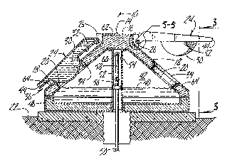
Figure 1 is a perspective view of the livestock waterer.
Figure 2 is a cross sectional view taken along line 2-2
l in Figure 1.
Figure 3 is an end elevational view taken along line 3-3
in Figure 2.
Figure 4 is a top plan view thereof.
Figure 5 is an enlarged fragmentary view of the lid
pivot connection to the top wall as seen in the designated
area labeled 5-5 in Flgure 2.
DETAILED DESCRIPTION OF THE PREFERRED EMBODIMENT
The animal waterer of this invention is referred to
generally ln Figure 1 by the reference numeral 10 and
includes an insulated tank 12. The tank 12 includes a top
¦ wall 14 having a center raised flat wall portion 16 and

1~91380
oppositely downwardly and outwardly sloping wall portions 18
which have circular access openings 20 close to the ground
surEace 22.
A lid 24 is pivotally connected to opposite sides of the
raised center wall portion 16 by a pin 26 which extends
through an opening 28 in the lid to provide a relatively
loose connection such that a downwardly extending semi-
spherical closure member 30 on the bottom face 32 of the lid
will be self-centering when it extends :lnto the access
openlng 20. Closure member 30 may be ~enerally downwardly
tapering and cylindrical in transverse cross section. The
closure member 34 engages the peripheral ed~e of the access
opening 20 such that ttlere is only line contact with the
closure member 30.
It is seen in Figure 2 that there is a substantial space
36 between the sloping wall 18 and the bottom ace of the .
lid 24 along its entire area which prevents any ice that
might build up on the sloping surface 18 interferring with
the sealing closure when the closure member 30 enters the
access opening 20. This is critically important to the
operation of this waterer since it depends on ground heat to
keep the water 40 in the tank chamber 42 from freezing. It
is also seen that the downward sloping surface 18 allows for
water dripping off animals' mouths to drain onto.the ground
rather than remain there to freeze and cause ice build up.
The sloping surface also causes the lid to fully close by
gravity. The lower edge 44 of the lid 24 extends sufficient-
ly beyond the vertical tank end wall 46 that an animal may
stick its nose under it to raise it up to gain access to the
opening 20.

~ 31380
¦ It is seen in Figure 2 that water 40 is supplied to the
¦ chamber 42 through a ground pipe 50 which extends upwardly
1 through a sleeve 52 which extends the entirs height of the
¦ chamber 42 and has a vent opening 54 to the interior of the
chamber 42 such that heat from the 0round 22 may rise and
1 enter the chamber 42~
¦ A float 56 ls connected through linkage 58 to a valve 60
in a conventional manner to maintain the water 40 at the
l level seen in Figure 2.
lO 1 The insulation 62 on the walls of the tank includes
three inches of urethane material. The tank will hold six
gallons of water sufficient to feed 80-100 animals such as
pigs or hogs. The insulation 62 includes a skin 64 on the
interior and exterior of high impact polyethylene.
Thus it is seen that in operatlon the animal waterer of
this invention will maintain the water in the tank in a
liquid state in the coldest of weather due to the fool-
proof construction which assures sealing of the access
l openin~ from above to keep the cold atmosphere air out of
¦ contact with the reservoir water. Ice cannot build up on
the sloping surface 18 since the water will run off before
it freezes and if it does freeze the lid 24 is spaced
sufficiently above the sloping surface to cause any inter-
ference with the closure sealing action between the closure
member 30 and the access opening peripheral edge 34.
Also, small animals such as pigs may easily ~ain access
to the water through the access opening 20 ~since it is close
to the ground and is partially vertically oriented and is
l small enough to prevent small pigs from entering and being
¦ drowned in the chamber 42.

~ 38~)
Cold air in the tank is displaced by entry of the
closure member 34 into the access opening 20 when the lid 24
is closed. The closure member includes a substantial amount
oE insulation material which by volume will displace a
corresponding amount of cold air froTn the tank thereby
raising the temperature in the tank.

Representative Drawing
A single figure which represents the drawing illustrating the invention.
Administrative Status

2024-08-01:As part of the Next Generation Patents (NGP) transition, the Canadian Patents Database (CPD) now contains a more detailed Event History, which replicates the Event Log of our new back-office solution.

Please note that "Inactive:" events refers to events no longer in use in our new back-office solution.

For a clearer understanding of the status of the application/patent presented on this page, the site Disclaimer , as well as the definitions for Patent , Event History , Maintenance Fee  and Payment History  should be consulted.

Event History

Description Date
Inactive: IPC from MCD 2006-03-11
Time Limit for Reversal Expired 2003-10-29
Letter Sent 2002-10-29
Grant by Issuance 1991-10-29

Abandonment History

There is no abandonment history.

Fee History

Fee Type Anniversary Year Due Date Paid Date
MF (category 1, 6th anniv.) - small 1997-10-29 1997-10-03
Reversal of deemed expiry 1998-10-29 1997-10-03
Reversal of deemed expiry 1998-10-29 1998-09-18
MF (category 1, 7th anniv.) - small 1998-10-29 1998-09-18
MF (category 1, 8th anniv.) - small 1999-10-29 1999-10-25
MF (category 1, 9th anniv.) - small 2000-10-30 2000-09-25
MF (category 1, 10th anniv.) - small 2001-10-29 2001-09-18
Owners on Record

Note: Records showing the ownership history in alphabetical order.

Current Owners on Record
AHRENS AGRICULTURAL INDUSTRIES CO.
Past Owners on Record
CLAUDE W. AHRENS
Past Owners that do not appear in the "Owners on Record" listing will appear in other documentation within the application.
Documents

To view selected files, please enter reCAPTCHA code :


To view images, click a link in the Document Description column. To download the documents, select one or more checkboxes in the first column and then click the "Download Selected in PDF format (Zip Archive)" or the "Download Selected as Single PDF" button.

List of published and non-published patent-specific documents on the CPD .

If you have any difficulty accessing content, you can call the Client Service Centre at 1-866-997-1936 or send them an e-mail at CIPO Client Service Centre.


Document
Description 
Date
(yyyy-mm-dd) 
Number of pages   Size of Image (KB) 
Cover Page 1993-10-23 1 11
Abstract 1993-10-23 1 22
Drawings 1993-10-23 1 48
Claims 1993-10-23 4 129
Descriptions 1993-10-23 5 171
Representative drawing 2000-07-28 1 25
Maintenance Fee Notice 2002-11-26 1 173
Fees 1994-10-20 1 76
Fees 1996-09-19 1 49
Fees 1995-09-18 1 41
Fees 1993-09-21 1 57