Note: Descriptions are shown in the official language in which they were submitted.
71697-13
ELECTROMAGNETIC ENERGY SEAL FOR A ~SICROWAVE OVEN
BACKGROU~D OF THE INVENTION
Field of the Invention
The present invention relates to an electromagnetic
energy seal for a microwave oven, and particularly to an
electromagnetic energy seal which can effectively prevent a
leakage of electromagnetic energy through a gap between the front
plate and the door of a microwave oven.
BRIEF DESCRIPTION OF THE DRAWINGS
The foregoing and further aspects of the present
invention will become more apparent from the following explanation
of the embodiments with reference to the accompanying drawings,
wherein:
Figure 1 is a perspective view showing a microwave oven to
which the pre~ent invention i8 applicable;
Figure 2 is a sectional view of a prior art electromagnetic
energy 8eal;
Figure 3 i8 a sectionalview of an electromagnetic energy seal
of the present invention;
Figures 4 and 5 are a perspective view and a plan view
respectively showing a folded outer wall with slits in accordance
with the present invention, respectively;
Figure 6 is a perspective view of a wave-guide, for
explaining the seal of the present invention;
Figure 7(A) is a schematic view showing a door frame used in
the test for the present invention;
Figure 7(B) is a schematic view showing a door frame
-- 1 --
i7
71697-13
utilizing an electromagnetic energy absorbing material; and
Figure 7(C) is a graph showing a comparison of the leakage of
electromagnetic energy with the door frames of Figures 7(A) and
7(B)-
Description of the Prior Art
Conventionally, a combination of a choke seal and a
capacitive seal has been used to prevent leakage of electro-
magnetic energy through the gap between the front plate and the
door of microwave ovens.
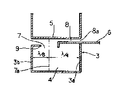
Referring to Figures 1 and 2, such conventional electro-
magnetic energy seal is shown, wherein a choke cannel 4 is defined
in the interior of a door frame 3 of a generally rectangular
channel ~haped cross section, which frame is disposed adjacent to
the outer peripheral edge of a door 2 of a microwave oven. On the
inner wall 3a of the door frame 3, a seal plate 6 i8 mounted par-
allel to a front plate 5 of the oven body 1, to form an opening 7
of a certain width between the door frame 3 and the seal plate 6.
The width, is determined such that the distance between the inner
wall 3a of door frame 3 and the center line 7a of the opening 7 is
~/4 (herein, ~is the wave length of the electromagnetic energy
adapted to heat a food). A gap 8 is formed between the front
plate 5 and the seal plate 6.
In the conventional electromagnetic energy seal of the
above-mentioned construction, the inner wall 3a of the choke
channel 4 functions as a short circuit plane to the electro-
magnetic energy leaked outwardly through the gap 8 out of the
heating area of the oven, so that the impedance of the inlet
~917~7
71697-13
8a of gap 8 is very low. This causes electromagnetic energy to be
reflected from said inlet 8a.
For example, in the case of a waveguide, the impedance
ZL at a distance d is represented by the equation:
L jZOtan 2 d
Wherein, j is ~--1 and ZO is the characteristic
impedance.
In the above equation, when the distance d is 4/~ , the
impedance ZL reaches an infinite value. On the other hand, when
the distance d is 2/~ , the impedance ZL becomes 0.
Accordingly, since the distance between the inner wall 3a of
the door frame 3 and the center line 7a of the opening 7 is about
~ /4 and the distance between the center line 7a and the inlet 8a
is about 4/~ in the above-mentioned construction, so that the
distance between the inner wall 3a and the inlet 8a is about
2/~ , the impedance at the inlet 8a becomes close to 0. As a
result, the electromagnetic energy i5 reflected from the inlet 8a,
so that the leakage of the electromagnetic energy through the gap
8 is avoided. Also, the gap 8 between the front plate 5 and the
seal plate 6 functions as a capacitive seal to present a low
impedance against electromagnetic energy, thereby preventing the
leakage of the electromagnetic energy.
In such conventional electromagnetic energy seal,
however, the following problems are involved.
(1) When the front plate 5 and the seal plate 6 contact with
each other at the point P to form a metal -to- metal contact
point, the metal -to- metal contact point P functions as a short
circuit. As a result, the impedance of the inlet 8a of the gap 8
~J~ 71697-13
cannot become low, and therefore, the choke seal is not formed.
As a result the leakage of the electromagnetic energy can not be
completely prevented.
(2) The above-mentioned effect of the choke seal is sharply
reduced, as the width of the gap 8 increases. This is apparent
from laboratory tests. Generally, the characteristic impedance of
the parallel transmission line formed by the front plate 5 and the
seal plate 6 is inversly proportional to the width of the gap 8.
For example, as the width of the gap 8 is increased from 50 ~m to
lmm (i.e. increased 20 times), the characteristic impedance is
reduced to about l/20th its value at 50 ~m.
On the other hand, in order to prevent the generation of
a spark between the seal plate 6 and the front plate 5, an instu-
lation film with a thickness of about 5~m is attached, or an
oxide film is formed on the seal plate 6 or the front plate 5.
Various dimension8 including the depth of the choke channel 4 are
determined by the parallel transmission line with a length of ~/4
formed by the door frame 3 and the seal plate 6, said seal plate
6, and said front plate 5. Generally, the density of the leaked
electromagnetic energy is formed to be minimum, when the width of
the gap 8 is about 50~m and the parallel transmission line having
a length of ~J4 is connected.
Therefore, even when these two ~/4 paths have different
characteristic impedances, dimensions of the choke system is
determined to exhibit a maximum effect under the above-mentioned
conditions. Thus, the change of the width of the gap 8 between
the front plate 5 and the seal plate 6 causes the characteristic
P~9~ 71697-13
impedance of the transmission line to be changed. In order to
prevent reduction of the choke seal effect, the width of the gap 8
should be accurately and firmly maintained, when the door is
mounted on the microwave oven. However, the width of the gap 8
gradually increases, due to the looseness of the door hinge caused
by the prolonged use thereof, so that the leakage of the electro-
magnetic energy is increased.
(3) The choke seal of the above-mentioned construction func-
tions effectively, when the electromagnetic energy enters at the
right angle with respect to the choke channel 4. On the other
hand, when the electromagnetic energy enters at an angle other
than the right angle, for example 45, with respect to the choke
channel 4, the width-wise wavelength of the choke channel 4
becomes ~ so that the effect of the choke seal iB greatly
reduced. The electromagnetic energy coming into the choke
channel 4 has a rectangular component and a parallel component
with respect to the longitudinal direction of the choke channel 4.
The choke seal is not effective against the parallel component of
the electromagnetic energy.
Consequently, the above-mentioned construction suffers
the disadvantage that it does not prevent leakage of the
electromagnetic energy entering the choke channel 4 at an angle
other than substantially a right angle.
SUMMARY OF THE INVENTION
It is an object of the present invention to provide an
electromagnetic energy seal for a microwave oven, wherein the
choke channel is provided with a tuning post adapted to generate a
~'7~
716~7-13
LC resonance located at the position in which the electric field
is strongest, so that the leakage of the electromagnetic energy is
effectively prevented.
In accordance with the present invention, this obJect can be
accomplished by folding the outer wall of the choke channel
inwardly to form a turning post forming member, determining the
interval in which the electric field is strongest as a function of
the frequency of the electromagnetic energy used in the microwave
oven, and cutting out slots in said tuning post forming member at
said intervals in which the electric field is strongest, thereby
forming a tuning post.
In accordance with the present invention there is provided an
electromagnetic energy seal for a microwave oven which comprises
an oven body, a door hinged on s~id oven body, and a door frame
having a generally rectangular channel shapéd cross-section
mounted at the outer peripheral edge of said door, a seal plate
fixed on the inner wall of said door frame and disposed parallel
to the front plate of said oven body to form an opening, the space
between the center line of said opening and said inner wall of
door frame being ~/4, characterized in that the ~pace between the
outer wall of said door frame and said center line of opening is
~ /8, and that said seal further includes a tuning post forming
member provided by an inwardly folded portion of the upper end of
said outer wall of door frame wlth slits therein of a uniform
width situated at intervals in which the electric fleld of the
electromagnetic energy is maximum.
~ ?,91 ~
71697-13
DETAILED DESCRIPTION OF THE_PREFERRED EMBODIMENT
Reference is made to Figures 3 to 5, which shows an
electromagnetic energy seal in accordance with the present
invention. As shown in the drawings, the door frame 3 having a
generally rectangular channel shaped cross-section includes a
tuning post forming member 9 which extends rectangularly from the
outer wall 3~ of said door frame 3, in accordance with the present
invention. The tuning post forming member 9 is formed by inwardly
folding a portion of the outer wall 3b of the doo~ frame 3, toward
the choke channel 4. The tuning post forming member 9 is provided
with spaces 10 which are formed by cutting sections of uniform
width from the tuning post forming member 9, at areas ln which the
field of electromagnetic energy i8 maximum. Preferably, the
interval T i~ less than or equal to ~/4 A~ clearly shown ln
Flgure 5, the wldth D of said hent member 1~ les~ than ~/4
(Dc ~ /4). The length L of the bent member ls no less than ~/32
and no more than ~/8 ~ ~/32 ~ L s ~/8.
The functlon and effect of the above-mentioned construction
according to the present invention will now be described in
detail.
Figure 6 shows a waveguide having the width m and the height
n, assuming m>~ and n~< ~. If the electromagnetic energy is
proceeding in the direction z, the distribution of the electric
field in the direction Y is uniform, because n<~ .
When it is desired to determine the TEmn mode in order to
determine the mode of the electrlc field dlstribution, if the
t~
1'79~
71697-13
electric field distribution is uniform in the direction Y, it i5
only needed to determine the TEmo mode, that is, the mode of the
electric field distribution in the direction X, because n is 0.
.. .
17~
71697-13
In the TEmo mode, the distance reaching the maximum
electric field point Xmax is represented as follows:
N.n
Xmax = 2
wherein, N is 1, 3, 5, ...., 2m-1.
And also, the condition under which a certain TEmo
mode presents is
~ c > 1
wherein, ~c is the cut-off wavelength of m , and
is a wavelength of the electromagnetic energy in a free space.
The gap 8 between the seal plate 6 and the front plate 5
in Figure 3 may be assumed to be the waveguide as shown in
Figure 6. When a tuning post is positioned within such waveguide
as shown in Figure 6, a LC resonance is generated between the
upper surface of the tuning po~t 11 and the facing wall surface of
the waveguide, thereby interrupting passage of the electromagnetic
energy in the direction Z. This effect will be maximum when the
tuning post 11 is po~itioned at the point of maximum electric
field.
In accordance with to this principal, the present
invention provides slits which function as a tuning post 11. The
interval of the slits 10 can be determined experimentally as
follows:
The microwave oven used in the test of the present
invention has the opening size of 299mm x 168.5mm. For this size,
the determined maximum electric field point XmaX is shown in
the following table.
71697-13
m (mm)Transmission C (mm) Xmax
Mode
TElo 598 149.5
299 TE20 299 74.75, 224.25
.
TE30 199.3 49.83, 149.5,
249.16
TE40 149.5 37.37, 112.12,
__ 186.87, 261.62
TE50 119.6 ~c < ~
wherein, the frequency of the electromagnetic energy is
2450 MHz, and the wavelength ~ i8 122.45mm.
After arranging all values for XmaX~ as determined
above, in order, the difference~ between respectivè adjacent
values are determined as follows:
261.62-249.16 = 12.46 ~ 12,5
249.16-224.25 = 24.91 . 25 = 2x12.5
224.25-186.87 = 37.35 ~. 37.5 = 3x12.5
186.87-149.5 = 37.37 ~ 37.5 = 3x12.5
149.5 - 112.12 = 37.38 - 37.5 = 3x12.5
112.12-74.75 = 37.37 '.37.5 = 3x12.5
74.75 - 49.83 = 24.92 ' 25 = 2x12.5
49.83 - 37.37 = 12.46 -, 12.5
37-37-0 = 37.37 ~ 37.5 = 3x12.5
299 - 261.62 = 37.38 -. 37.5 = 3x12.5
As apparent from the above, the maximum electric field
_ g _
~?~9~7~
71697-13
points XmaX are positioned at intervals of 12.5 K mm (herein,
K is a constant). Accordingly, when slits 10 are arranged at
intervals T of 12.5mm, they are disposed at the maximum electric
field points Xmax
For other opening sizes, the period interval T of slits
10 can be calculated in the same manner. For example, the
interval T of slits 10 is about 13mm, for the opening size of
168.5mm. The microwave oven, in which slits 10 were located at
intervals T as calculated above, leaked electromagnetic energy at
a greatly reduced rate as compared with a microwave oven in which
an electromagnetic energy absorbing member is provided.
Figure 7(A) shows detailed dimensions of the door in
accordance with the present invention which was tested for leak-
age. Figure 7(B) shows a door having the same dimensions as in
Figure 7(A), but using the electromagnetic energy absorbing member
12 made of a ferrite which was also tested for leakage. The
results of the tests for leakage of electromagnetic energy for the
two doors is shown in Figure 7(C).
When the size of the heating area of a microwave oven is
relatively large, the interval T of slits 10 is small. However,
when the interval T is very small, a difficulties in manufacture
occur. Therefore, slits 10 are alternatively arranged by prede-
termining at least two large period intervals. In this case,
slits 10 are non-periodically arranged, as a whole. When this
interval is very large, it is impossible to cut off leakage of the
electromagnetic energy moving in the direction parallel to the
choke channel 4. Therefore, the interval T of slits 10 should not
-- 10 --
71697-13
be more than ~/4.
As is apparent from the above description, the present
invention effectively prevents the leakage of the electro-magnetic
energy, by utilizing the principle that when a tuning post is
positioned in the location in which the electric field is
strongest, passage of the electromagnetic energy is effectively
interrupted. The present invention, eliminates the need to use a
separate electromagnetic energy absorbing member. Moreover, the
leakage of electromagnetic energy oriented rectangularly and
inclinedly can be effectively cut off. In addition, the
effectiveness of the electromagnetic energy seal is not reduced,
when the door hinge is loosened due to the prolong use thereof,
improving the reliability of the oven.