Note: Descriptions are shown in the official language in which they were submitted.
"IMPROVEMENTS IN APPARATUS FOR INJECTING SUBSTANC~S
INTO LIQUIDS"
The present invention concerns improvements
in apparatus for injecting substances into liquids.
5More particularly, the injection apparatus
is primarily meant f`or injecting gases, gases plus
powders, or solids - usually accompanied by gases,
into potentially dangerous liquids, e.g. molten
metals such as iron and steel. The purposes of in-
jecting such substances are numerous and diverse.
Our International Patent Application, Publication
No. W084~02147, outlines some of the reasons for
introducing substances into molten metals and in
this connection reference is directed to that pub-
lication f~or f`urther details.
Like W084/02147, the present invention pertains
to apparatus for injecting substances through a
wall of a melt containment vessel such as a ladle.
The wall could be the bottom or more usually the
side of the vessel. The apparatus is of the type
comprising a refractory block for installing in
the vessel wall, the block being pierced by an in-
jection passage in which a delivery pipe is movable
;forcibly towards a liquid-facing end thereof, to
3~
~ 2 --
permit injection to commence by breaking or dis-
lodging a passage bloc~ing element which is temp-
orarily located at or in this end to prevent melt
entering the passage before injection is commenced.
~y expelling, breaking or dislodging the blocking
element, the pipe opens the passage for admitting
into the melt a substance delivered via the delivery
pipe.
If the blocking element is prematurely or
accidentally unseated from the end of the passage,
melt could rapidly enter the passage due to the
static pressure of the melt. Under some circumst-
ances, the melt might leak from the vessel via the
passage, e.g. thrusting the delivery pipe from the
passage as it does so. This could obviously be danger-
ous. Alternatively, the melt might enter the passage
and freeze therein, effecti~ely sealing the passage
and preventing the subsequent injection of substances
into the melt. Unseating of the blocking element
due to careless installation and/or premature advance-
ment of the pipe is thus to be avoided and this
invention alms to prevent such inadvertent advance-
ment in a simple but effective manner.
Aocording to one aspeot of the present in-
vention, there is provided apparatus of the type
Z~
hereinbefore defined, for injecting substances intoa liquid through the wall of a liquid containment
vessel, wherein the delivery pipe is part of a lance
assembly and wherein positioning means including
a detent arrangement acting between said assembly
and a fixed part of the apparatus define a stop
for locating the lance assembly at a predetermined
ready position prior to injection.
In a preferred embodiment, the stop defined
by the detent arrangement locates a discharge end
of the delivery pipe spaced from the passage blocking
element a predetermined distance and prevents in-
advertent displacement of the pipe into contact
with the blocking element~ The detent arrangement
can be overcome when a predetermined advancing force
is dellberately exerted on the lance assembly, said
force belng made greater than any force that cou1d
: be applied manually.
: The~detent arrangement preferably also defines
a second stop preventing inadvertent withdrawal
or ejection of the lance assembly from an advanced,
injection position thereof~
The detent arrangement can comprise a spring
-loaded element on the one hand which coacts with
an abutment on the other hand; the former may be
~LZ~Z~
-- 4 --
housed in the fixed part of the apparatus when the
latter is mounted on the lance assembly, or vice
versa. Preferably two detents act on the lance ass-
embly.
According to another aspect of the present
invention, the stop enabling the lance assembly
to be held in a predetermined position prior to
injection comprises a shear pin and an abutment.
The abutment shears off the shear pin allowing the
lance assembly to be advanced to its injection pos-
ition when a predetermined advancing force is del-
iberately exerted on the assembly. The force nec-
essary to shear the pin is made greater than any
force that can be applied manually.
~ Convenlently, the~ shear pln is mounted on
the movable lance assembly and the abutment is on
an immobile part of the apparatus. The stop func-
tions, like the detent arrangement, to locate a
discharge end of the delivery pipe spaced away from
the blocking element until such time as the predet-
ermined advancing force is applied.
As disclosed above the detent arrangement
can also define a second stop preventing inadvertent
:
displacement of the lance assembly from the advanced,
; 25 injection position thereof. Accidental withdrawal
~:: :: : : ~ :
2.~
of the assembly after injection has commenced, or
its ejection due to the pressure of the liquid,
could be highly dangerous since the high temperature
liquid or melt could then escape from the vessel.
In the second embodiment of the present in-
vention, the shear pin and abutment cannot also
serve as a second stop for preventing withdrawal
or ejection after initiating injection, because
the shear pin is broken when the lance assembly
is first moved to its injection position. A second
stop can, desirably, be provided by another abutment
on an immobile part of the apparatus and a companion
abutment which is part of the lance assembly.
In one embodlment, the lance assembly can
have a lance head member comprising a pair of or-
ificed bodies, held together by a pivot bolt for
one body to be swung relative to the other. Before
and during injection, the bodies are so oriented
that their orifices register to permit passage of
an injectant. When an injection is adjudged com-
pleted, the said one body was swung, upon the pivot
bolt, relative to the other body causing its orifice
to move out of registry with the orifioe in the
other body. Injection was thereby quickly stopped.
The design of another embodiment involves
Z9~
-- 6 --
simplified machining operations and requires assemblyof fewer component parts.
In this other embodiment, the lance head comp-
rises but two parts, both orificed; one part is
slidable in the other to shift its orifice out of
conjunction with the orifice in the other part to
terminate injection. When the slidable part is so
shifted, the design is such that it projects from
the other part, then serving as an abutment which
coacts with an abutment on an immobile part of the
apparatus to prevent a potentially dangerous with-
drawal or ejection of the lance assembly. Such a
structure is particularly simple to put into practice
as will be appreciated from the following description.
In essence, a preferred lance head may comprise
a cylinder pierced axially by an injectant passage.
The cylinder acts as a union between the lance pipe
and an injectant supply conduit. It is pierced trans-
versely too, for closely accommodating an orificed
plug. The plug can be shifted to terminate lnjection
suddenly, and when shifted it coacts with the im-
mobile abutment to serve as a check against with-
drawal or eJection of the lance assembly.
A suitable ram is employed for displacing
the pivotable or shiftable part of the lance head.
19
6a 24101-240
Accordingly, the invention herein comprises apparatus
for installation in the wall of a llquid containment vessel for
injecting substances into a liquid therein, including a refractory
block which is pierced by an injection passage, has an injectant
delivery pipe -therein and has a passage blocking element
temporarily l.ocated at or in a delivery end of the passage to
prevent liquid entering the passage before :injection is commenced,
the pipe being movable forcibly in the passage at the said element
to break or dislodge said element to open the passage for
injection, wherein the delivery pipe is part of a lance assembly
and wherein positloning means acting between the said assembly and
a fixed part of the apparatus define a stop for locating the lance
assembly at a ready position prior to injection.
, ,i,
The invention comprehends methods of injecting
substances into molten metal, which entail use of
apparatus disclosed and claimed hereinaf`ter.
The invention will now be clescribed in more
detail by way of example only with reference to
the accompanying drawings of preferred embodiments
thereof. In the drawings:
Fig. 1 is a general, partial cross-sectional
view through the apparatus according to this in-
vention, taken on line I-I of Fig. 2;
Fi~. 2 is a partial end view of the apparatus
shown in Fig. 1;
Fig. 3 is a part-sectional view on line III-III
in Fig. 2;
Fig. 4 is an elevational view of part of the
apparatus as viewed in the direction of arrow IV
in Fig. 2;
Fig. 5 is a cross-sectional view of a lance
head attached to a dellvery pipe installed in the
apparatus of Fig. 1;
Fig. 6 is an elevational view of the lance
head shown in Fig. 5;
Fig. 7 is an end view of the lance head,
looking towards the right hand end of the head as
illustrated in Fig. 6;
~29;~
-- 8 --
Fig. 8 is a general, partia:L cross-sectional
view through another apparatus according to this
invention, and
Figs. 9 to 11 are cross-sectional views of
a lance head attached to a delivery pipe installed
in the apparatus of Fig. 8, showing also safety
stops and their function during operation.
In the several drawings, like parts have the
same reference numerals allocated thereto wherever
possible.
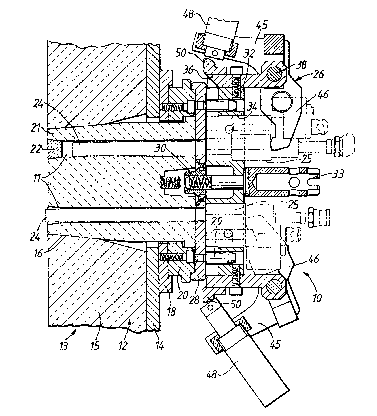
The apparatus 10 shown in Figs. 1 and 8 of
the accompanying drawings has a plurality of in-
jection passages 11 for flexibility in use. ~ith
this apparatus different substances, and substances
in different physical forms, can be injected sim-
ultaneously or in some chosen sequence into a high
temperature liquid such as a molten metal. The ill-
ustrated apparatus may, for instance, have four
passages 11. Apparatus according to the invention
could have more or less than four passages : we
have designed versions having eight and fifteen
passages. Injectlon apparatus having but one in-
jection passage is also within the scope of this
invention.
The apparatus 10 can be used safely to intro-
duce substances such as reagents into any liquid
92~
which is potentially dangerous, e.g. due to being
at elevated temperature. It has, however, been partic-
ularly developed for use in metallurgical processes,
more especially ferrous metallurgical processes,
where the liquid is a molten metal or alloy. The
melt temperature may be up to 1600C or higher,
depending on the metal. The following description
refers to melts for convenience, in view of the
principal use for which the apparatus was developed.
Apparatus 10 is installed in the bottom or,
more usually, the side wall 12 of a vessel 13 e.g.
a ladle. The wall 12 comprises a metal shell 14
and an insulating inner lining 15. The apparatus
is located so as to inject substances deep into
the melt contained in vessel 13, for instance at
a level of 1 metre or more below the melt surface.
The wall 12 is provided with a suitably-located
injection opening 16 with which the apparatus 10
is registered. Around the opening 16, to the shell
14 an annular adaptor plate 18 is welded; the app-
aratus 10 is fastened to the vessel by way of the
adaptor plate 18.
An annular location plate 20 is bolted to
the adaptor plate 18 for positioning a re~ractory
block 21 properly in the opening 16. Block 21 is
2~
-- 1 o --
normally cemented in said opening to the lining
15. The refractory block in this embodiment is
pierced by a plurality of injection passages 11
to form a plural-shot nozzle. There may, for in-
stance, be four passages. Before injection commences,the passages 11 are closed at their inner ? melt-
facing ends by blocking elements (not shown in Fig.
8). The passage blocking elements 22 in Fig. 1 are
shown located in the passages, but they could be
cemented, across their passages, to the end face
of the block 21. The blocking elements 22 are made
of a suitable refractory material, and are so fitted
to the block that they can be expelled or detached
from their passages 11 when injection is to commence.
If said elements are cemented across the discharge
ends of the passages, either the cement chosen is
one that provides a weak bond enabling the elements
to be dislodged, or the elements are made of a frang-
ible matériaI.
; Q lance assembly is associated with each pass-
age 11. The lance assemblies comprise delivery pipes
24 and inlet heads 25. The former are movable length-
wise in the passages 11 and the latter are disposed
outwardly of the block 21. Means 26 (not shown in
Fig. 8) are provided to advance the lance assemblies
:~Z~3~
forcibly in the direction of the vessel interior,
in order for the pipes 24 to dislodge or break the
passage blocking elements 22 for commenclng an in-
jection. The said means 26 can be activated e.g.
pneumatically or hydraulically. The pipes 24 are
made of metal e.g. stainless steel, calorized steel
or have a composite metal/refractory structure.
In Fig. 1, a circular cover plate 28 is de-
tachably fastened to the location plate 20 such
that openings in the cover plate register with ass-
ociated ones of the injection passages 11. Plate
28 clamps nozzle block 21 in place in the opening
16. Location pins 29 and a central nut 30 are mounted
on the cover plate 28. Said pins enter appropriately-
positioned receiving bores in a location block 32which is assembled to the cover plate by a bolt
33 engaged with the nut 30. For the four-passage
design shown in Fig. 1, the location block has a
four-lobed shape and four apertures 34 arranged
relative to the lobes as shown in Fig. 2. The ap-
ertures 34 of the mounted location block 32 suitably
register with the passages 11 and the associated
plate openings and are of larger diameter than the
latter. In combination with the cover plate, the
25 location block apertures 34 provide pockets into
-
- 12 -
which the inlet heads 25 fit slidingly.
An advantageous and convenient feature of
this invention resides in the design or construction
of the parts employed for exerting proper control
over the lance assemblies before, during injection
and upon stopping injection.
Secured to the location block 32, at the end
of each lobe, is a mounting member 36 which has
a bore for receiving a pivot pin 38. By means of
the pivot pin, lance advancing means 26 or lance
clamps 40 are interchangeably and pivotally fastened
to the location block 32. The lance clamps 40 are
shown in Fig. 4. They are a convenient but not ab-
solutely essential feature of the invention. Their
purpose is to clamp the lance assemblies for safety
in proper positions before and after injections.
When an injection run is to be carried out, the
clamps 40 are dismounted from the member 36 and
advancing means 26 are substituted for them. The
apparatus 10 can have two lance clamps 40 and two
advancing means 26, whereby the apparatus can be
ready to inject through two passages 11 simultan-
eously or in quick succession. If desired, there
could be three clamps 40 and one advancing means
26- As stated, however, the clamps 40 can be omitted.
19
Then, four advancing means 26, which incorporate
hydraulic rams, can be used in their stead to clamp
all the lance assemblies safely in their proper
pre- and post-injection positions.
As shown in Figs. 2 and 4, each clamp 40 com-
prises a rigid fabrication or clamp body 41 having
two arms 42 bearing against the lance inlet head
and holding the latter in position. A manually-
adjustable thrust screw 43 is threaded to the clamp
and thrusts against the mounting member 36.
Clearly, adjustments of the screw 43 effect pivoting
of the clamp body 41 on the pivot pin 38 and thereby
alter the position of the arms 42 bearing on the
inlet head 25, so the clamp 40 can be set to hold
the lance assem~ly in a chosen position. The chosen
position before injection is determined by a stop
to be described. Said stop is shown in Figs. 3,
6 and 7. After injection the position can correspond
to the lance locatlon when its inlet head is bottomed
in the pockets formed by apertures 34 in the location
block 32.
The advancing means 26 also comprises a rigid
fabrication or actuator body 45 having a pair of
: spaced arMs 46 extending therefrom for bearlng upon
a lance inlet head 25. The body of an hydraulic
1~9 ~ 1~9
- 14 -
actuator or ram 48 is fastened to the body 45 and
has a piston advanceable into contact with an abut-
ment 50 on the mounting member 36. When the ram
is energised, the piston pushes against the abutment
50, urging the ram body away therefrom. Accordingly,
the actuator body 45 is urged to pivot about the
pivot pin 38 thrusting the arms 46 in the direction
of the vessel wall. By suitably energising the ram
48, the arms 46 of the advancing means 26 can hold
the lance assembly at the pre-injection position,
can advance the assembLy for dislodging the passage
blocking means 22 to commence an injection, and
can hold the lance assembly in the post-injection
position.
The inlet heads 25 of Figs. 1j ~and 5 to 7
are eaoh constructed ln~two parts along the lines
dlsclosed in our GB-A-2,171,i86 and PCT/GB87/00l17
to which attention is hereby directed. The outer
one of the two parts is displaceable relative to
; 20 the other part for rapidly terminating an injection.
- To effect the displacement, the same actuator body
45 of advancing ~means 26 mounts a second hydraulic
ram 52 so that its piston can bear upon an abutment
; 53 fast with the outer part of the lance head.
Several benefits are obtained by forming a
`:
:
-` ~29~ 19
- 15 -
composite or unitary structure from the actuator
body 45 and the two rams 48, 52 and by providing
a single attachment (pivot 38) to the location block
32. After injection, the delivery pipes and the
nozzle block 21 will routinely need replacing. The
ready mounting and dismounting of the unitary struc-
ture eases such routlne servicing by minimising
disassembly. Moreover ? it is easy to remove the
unitary structure from one injection site of the
10 apparatus, to locate it quickly at another injection
site and to substitute a simple lance clamp for
said structure. By this means, the need for each
site to possess its own permanent actuation structure
is avoided, saving cost and simplifying the overall
15 installation.
The lance inlet head 25 is shown more partic-
ularly in~ Flg. S; its~inner and outer parts 54,
56 meet at a plane interface and are held securely
`
together by a combination of a draw bolt and a spring
20 58. Each part is plerced by a passage 54', 56' and
the two passages~ are aligned before and during in-
jeotion. The aligned passages convey injectlon ~sub-
~stances, i.e. gas, gas and powder~ or wire from asuppIy conduit 59~to the delivery pipe 24. The abut-
ment 53 secured to the outer part 56, detachably
:
-
~9~
for a purpose which need not be explained here,
is engaged by the piston of ram 52 when it is desired
to terminate injection. On activating ram 52, the
abutment 53 is displaced and with it outer head
part 56. The latter rotates relative to the head
part 54 on the draw bolt, which serves as a pivot.
Head part 54 cannot rotate in view of its seating
in the aforementioned pocket provided by the aperture
34 in the location block 32. The relative rotation
of part 56 moves passage 56' out of registry with
the companion passage 54' and hence closes the route
from the supply of the injection substance(s) to
the delivery pipe 24. Where the lance assembly is
used for conveying an injection substance in the
form of a wire strand, the parts 54, 56 will include
shear bushes operative at the plane interface to
sever the strand upon activation of ram 52.
A particular inventive feature of this develop-
ment is the stop mentioned hereinbefore. The stop
is shown in Figs. 3, 6 and 7 to which reference
is now made. In essence, the stop is a detent oper-
ative between the or each lance assembly and some
suitable fixed part of the apparatus 10. For each
lance assembly, the detent in its simplest form
comprises a spring-loaded plunger and an abutment,
~L2~Z119
one affixed to the lance and the other to the fixed
part of the apparatus. As shown, the spring-loaded
plunger 60 is located in a housing 61 formed jointly
by the location block 32 and thle mounting member
5 36 (the fixed part of the apparatus). The housing
61 is positioned adjacent a respective aperture
34 in the locating block 32 and a bore extends from
the housing to the aperture. A shank 62 of the
plunger 60 extends through the bore. A spring in
the housing 61 acts upon an enlarged head of the
plun8er 60 to urge the stem 62 into the aperture
34. The tip of stem 62 coacts with an abutment
affixed to the lance head 25, and more particularly
to the inner head part 54, when the lance head is
loeated in the aperture 34. The abutment 64 has
inclined front and rear faces or ramps 66, 65 engage-
able by the plunger 60. The plunger 60 and front
ramp 66 define a stop which determines the position
of the lance assembly before injection commences.
2Q In this posltion, the delivery pipe 24 is set back
from the passage blocking element 22. By correct
design and choice of spring, it is made impossible
for anyone manually to displace the lance assembly
forwardly past the stop. For example, a force of
some lJ2 ton (508 k6) may be needed to advance the
- 1;292~19
- 18 -
assembly past the stop, i.e. to cause ramp 66 past
the detent plunger. Thus, inadvertent dislodging
of the blocking element 22 through careless handling
or installation is prevented.
The advancing means 26 is, however, well
capable of developing the force needed to move the
lance assembly and overcome said stop. When so moved,
the rarnp 66 displaces the plunger 60 inwardly rela-
tive to the housing 61 against the spring bias,
10 and a point is reached where the tip of the plunger
is on a dwell face 68 of the abutment 64. During
continued movement of the lance assembly by advancing
means 26, the passage blocking element is dislodged
so injection can commence. Ultimately, the lance
~15 assembly reaches a fully advanced position when
the plunger 60 and rear face 65 of the abutment
coact to define ~a~second stop and prevent manual
retraction of~the lance assembly from its injection
position. The second stop also prevents rearward
20 ejec~ion of the lance assembly by the pressure of
the melt.
When all the injections ~have been carried
out~ the~ delivery plpes 24 are firmly welded in
their forward positions into their respective pass-
25 ages 11 by metal that ~has frozen in the spaces bet-
:: :
~.2~
- 19 --
ween the delivery pipes and the passages.
With the lance heads 25 in their forward pos-
itions, the rear ramp faces 65 have passed to the
front of plungers 60. It is then possible to remove
the location block 32 after unscrewing bolt 33 with-
out interference, and the lance heads 25 can be
unscrewed from the delivery pipes 24. By means of
appropriate tooling affixed to the delivery pipes
24, they and the refractory nozzle block 21 can
be extracted for replacement.
A particular advantage of the illustrated
detent is its ability to assist in cleanly dislodging
the blocking element 22 from the end of the injection
passage 11. When the lance assembly is moved forwards
to commence dislodging the blocking element 22,
a point is reached where the rear ramp 65 approaches
the plunger 60. When the latter contacts the rear
ramp 65, the spring biasing on the plunger 60 has
the effect of suddenly thrusting the abutment 64
forwards and with it the lance assembly; the sudden
forward~ movement caused by the camming effect of
the spring-loaded plunger on the rear ramp 65 results
in the delivery pipe suddenly ejecting the blocking
element 22.
25As described, there can be but one detent
acting between the or each lance assembly and the
fixed part of the apparatus. For preference, however
~there are two detents acting in concert. Thus, fitted
; on each lance assembly there are two diametrically-
opposed abutmentg 64 and two spring-loaded plungers
1 9
- 20 -
are therefore housed in the location block 32.
Conceivably, the abutment could be made part
of the fixed location block and the spring-loaded
plungers could be carried by or incorporated in
the lance assemblies, but for design purposes it
is preferred that they are arranged as described
and illustrated.
The apparatus 10 shown in Fig. 8 has been
described in part already, in conjunction with Fig.
1 above. The principal differences embodied in the
Fig. 8 arrangement will now be described, followed
by a description of the lance head arrangement des-
igned for use with this apparatus.
In the apparatus 10 of Fig. 8, a circular
mounting plate 2a is detachably fastened by means
not shown to the location plate 20, such that open-
ings in the mounting plate register with the in-
jection passages 11. Plate 28 again clamps the no~zle
block 21 in place in the opening 16. A central nut
or boss 130 which is internally screw threaded is
mounted on the plate 28, and location block 32 is
assembled to the mount~ing plate with a collar portion
133 of block 32 telescoped over the boss 130. The
location block has a plural lobed shape having
as many lobes as there are passages 11 and lance
~LZ92~19
assemblies, the lobes suitably registering with
the passages 11 and the openings in the mounting
plate 28. Recesses 134 in the periphery of the loc-
ation block 32 provide pockets in which the inlet
heads 25 fit and are capable of moving slidably.
A cover 135 consisting of a circular plate
136 and skirt 137 is fastened to the apparatus 10
by a nut 138 which engages a central screw threaded
spindle 140 which is screwed into the boss 130.
The spindle 140 has an enlarged portion to engage
the locating block 32 and clamp the latter to the
mounting plate when the spindle is screwed into
the boss 130.
An advantageous and convenient aspect of this
invention resides in the provision of and design
: or construction of the parts employed for exerting
proper control over the positioning of the lance
assembly before, during injection and upon stopping
injection.
: 20 As with the flrst described embodiment, means
is provi~ded to render the lance assemblies of the
: embodiment of Figs. 8: to :11 captive in the apparatus
before injec~ionj and means is provided to render
them captive after commencing an injection.
For rendering the lance assemblies captive
:
:: : :
~Z~12~
- 22 -
before injection, each is provided with an abutment
element that coacts with fixed abutments on immovable
parts of the apparatus lO. The lance abutment element
is a shear pin 142 fastened to and projecting from
a head member 25 of the lance. The shear pin is re-
ceived in a slot 143 in the location block 32. The
pin extends radially inwards, towards the central
fastening means 130, 138 and 140, and the slot 143
is radially outwardly open to accept the pin. The
s]ot 143 ends in an abutment face 144. The shear pin
142 and abutment face 144 on immovable location block
32 check premature movement of the lance assembly
towards the interior of the vessel 13 and the passage
blocking element, not shown. They locate a discharge
end of the lance delivery pipe set back a predetermined
~distance from the passage blocklng element. To advance
a lance assembly so as to break or dislodge the assoc-
iated passage blocking means, the assembly has to
be thrust forward with sufficient foree to snap the
shear pin 142. The force, which i5 substantial, is
greater than can practically be exerted manually on
the lance assembly. The force is exerted through a
pneumatic or hydraulic actuator, not shown, which
acts on a thrust/coupling member 145 connectsd be-
.
~2~
tween the lance head 25 and a conduit leading to
a supply of injectant. The actuator can be similar
or equivalent to advancing means 36, 48 of the first
described embodiment.
The shear pin 142 also coacts with an inner
face of the cover plate 136, preventing withdrawal
of the lance assembly after installing it in the
apparatus 10 and before an injection is commenced.
The lance assembly seen at the top of Fig.
8 is in the pre-injection position, the shear pin
142 being in the sl~t 143 in contact with the lance
locating abutment face 144.
The locating block 32 further defines a second
slot 146 located closer to the mounting plate 28
than slot 143. Slot 146 also opens radially out-
wardly, and at ltS end further from plate 28, the
slot terminates in a second abutment face 148. Abut-
ment face 148 coacts with an abutment of or on the
lance head 25 to prevent withdrawal or ejectlon
of the lance assembly after injectlon.
The lance~ head 25 is a particularly simple
fabrication. It is in two parts. The first part
150 comprises a cylindrical metal bar pierced axially
by a passage 151 for conveying injectant from a
supply condult to the delivery pipe 24. The passage
~Z9;2~L19i
- 24 -
is counterbored at opposite ends of head part 150,
and the counterbores 152, 153 are screw threaded
for attaching the supply conduit and delivery pipe
24 respectively to the head part 150. The shear
pin 142, which may be a small brass rod, is fastened
in a radial bore provided therefor in the head part
150.
The head part 150 is also pierced by a trans-
verse bore 154 that intersects passage 151. A second
cylindrical part 155 of the head 25 tightly but
movably fits in the transverse bore 154. The second
head part 155 is traversed by a passageway 156.
Before and during injection, the head parts 150,
155 are so disposed that passage 151 and passageway
156 are in registry for injectant to flow to the
delivery pipe. In thls position, one end 158 of
head part 155 projects radially from the head part
: 150; the opposite end 159 does not project, however.
Incidentally, after injection has commenced,
the projecting end 158 can coact with the cover
plate 136 to render the lance assembly captive to
the apparatus 10. In the unlikely event of failure
of a hydraulic or pneumatic actuator acting on thrust
member 145, the pressure of the melt can push the
lance assembly outwardly only a short distance,
gZ~19
- 25 -
until movement of the assembly is checked by the
head part 155 striking plate 136.
Injection is stopped by shifting the head
part 155 in bore 154 of the first head part 150,
moving passageway 156 wholly out of registry with
passage 151. To shift the head part 155, a hydraulic
or pneumatic ram 160 mounted on the cover 135 is
activated. Ram 160 has a push rod 161 positloned
generally in line with the end 158 of head part
155 when the lance assembly is in its forward, or
injection, position. The push rod 161 has access
to the end 158 through a slot 162 in the skirt 137
of the cover. The ram 160 displaces head part 155
causing end 159 thereof to project radially from
head part 150. This movement of head part 155 is
arrested by a ~stop surface 164 provided on the collar
133 of the locating block 32.
Upon closing off the flow of injectant by
ram 160, melt enters and freezes in the discharge
; 20 pipe 24, blocking it. The pressure of the melt may
: : urge the lance assembly outwards. Outward movement
is safely limited, however, by the projecting end
159 of head part 155 moving into abutment w~th abut-
ment face 148 on the immobile location block 32.
The lance aasembly shown above the centreline
2~1~
- 26 -
in Fig. l is in a pre-injection or ready position,
when the lance head is shown - enlarged - in Fig.
2. The effect of the shear pin 142 and abutment
face 144 in properly locating the lance head 25
and hence the lance assembly can be readily discerned
from Fig. 9.
For initiating injection, the lance assembly
is forcibly advanced leftwards, in the direction
of the vessel interior, snapping the shear pin 142
against abutment 144 and unblocking the passage
11. Fig. lO shows the lance head position relative
to the abutments 144, 148 after the lance assembly
has been advanced to the injection position.
Fig. 11 shows the lance head still in the ad-
vanced posltion, a~ter the head part 155 has beendisplaced to terminate inJection. Ejection or with-
drswal of the lance assembly in a rightward or out-
ward direction will now be prevented by the obstacle
presented by abutment 148 to the projecting end
159 of head part 155.
With a plural passage injection device acc-
ording to thls embodiment of the invention, the
several lance assemblies are installed in the lobed
location block 32 with the cover 135 dismounted
from the apparatus 10. The assemblies are restricted
~ 9
- 27 -
to the pre injection position by the stop means
142, 144. The cover 135 is then fitted.
The cover 135 may be arrangecl such that but
one lance assembly can be advanced and used at
a time for injection. To this end, the plate 136
has a single aperture 170 giving access to a selected
lance assembly. The thrust/coupling member 1~5
is passed through this aperture 170 and abuts lance
head 25, and an actuator is engaged with the member
145 for advancing the lance assembly when required.
The actuator 160 is secured at a fixed location
to the cover 135 corresponding to the selected
lance assembly. Af`ter injection via this assembly,
the member 145 is disconnected therefrom and the
nut 138 released sufficiently to enable the cover
135 to be rotated. The actuators may be disengaged
from the used assembly or removed, as necessary
to free the cover 135 for rotation. The cover 135
is then rotated until its aperture 170 is aligned
with another selected, unused lance assembly where-
upon the cover is locked in position by nut 138.
The member 145 is then fitted and the lance advanc-
ing actuator (not shown) is suitably engaged there-
with.
When all the lance assemblies have been used,
92~1~
- 28 -
the cover 135 is dismounted and the male threaded
spindle 140 is unscrewed from the female threaded
boss 130. The location block 32 can then be dis-
mounted and the heads of used lance assemblies
can be unscrewed for re-use.
The nozzle block 21 is removable from the
opening 16 9 for example for replacement after de-
taching the mounting plate 28. If, as often will
happen, the lance pipes become welded or frozen
into the block 21, the latter can be removed by
pulling on the lance assemblies. Should the lance
pipes pull from the block 21 leaving the latter
still in the opening 16, then the block can be
removed by a suitable puller which is attached
to a threaded anchor 72 cast or moulded into the
block.
As a practical matter and with the user's
convenience in mind, it is contemplated that in
most cases the nozzle block will be scrapped and
replaced by a new block every time all the lance
assemblies have been used, so that neither the
block nor the lance pipes will be reused.
It should be appreciated that the foregoing
~;~9
-- 29 --
description is illustrative only and that various
changes may be made within the scope of the appended
claims.
Industrial Applicabilit~
The invention is applicable for introducing
substances to aggressive liquids and melts which
are at high temperatures, such as molten metals.
Thus, the invention can, for instance, be used in
ferrous metallurgy for introducing gaseous, solid
or particulate materials into molten steel or iron,
for various purposes. Thus, using the invention
one can introduce alloying elements, especially
readily volatilizable elements such as aluminium
and potentially hazardous, volatilizable elements
such as lead. Substances used for grain refinement
or for controlling carbide formation can be intro-
duced similarly. Likewise, the invention can be
used to introduce substances used e.g. to desul-
phurise, de-lliconise or dephosphorise the melt.