Note: Descriptions are shown in the official language in which they were submitted.
Z39~
S-7085
SURGICAL DRAINAGE APPARATUS
This invention relates to surgical drainage
apparatus and, more particularly, to a drainage device
for collecting fluids from the thoracic cavi-ty.
Thorac;c drainage devices are normally used to
remove gases and air as well as blood or other liquids
from the pleural cavi-ty surrounding the lungs.
Typically, such drainage is needed after chest surgery,
after infliction of a chest wound or in some cases
simply to remove excessive amounts of fluid tha-t may
accumulate as a result of an illness, such as
pneumonia.
Thoracic drainage is carried out either under
gravity or by application of a slight suction. One
type of suct;on dra;nage system that has been long
employed is known as a three bottle sys-tem in which one
bottle is used to collec-t -the body fluids, a second
bottle provides a liquid seal to prevent backflow of
-the fluids to the patient, and a third bottle regula-tes
the level of suction. The bottles are often of glass.
Various devices have been developed to replace
the breakable glass bottles used in prior art systems
and to combine the functions of two or even three of
the bottles into a single unit. For example one such
device combines a collection conta;ner with a liquid
seal chamber. It is desirable that -the liquid seal be
maintained a-t all -times because if the seal is lost the
drainage unit may no-t function properly and the
patient s l;fe maybe placed in danger.
~2~3~
S-7085
--2--
Coughing or gasp;ng can deple-te the liquid seal and
all.ow backflow of fluids and solids -to the patient;th;s
may make patient breathing more difficult and may also
introduce infection.
It is highly desirable to mon;tor bubbling of gas
through the liquid seal since -this gives an indication
of the strength and condition of the patient's
respiratory sys-tem. Visibility of the lower part of
the liqu;d seal ;nlet tube ;s also very des;rable in
order to observe the rise and fall of liquids
(tidalling) in response to changes in pressure ;n the
pleural cavity. This is a useful indica-tion of the
strength & regular;-ty of pat;ent breath;ng. One
problem with pr;or art devices is that the liquid seal
chamber may fill w;th foam thus obscur;ng the ;nlet
tube and making i-t difficult for an observer to monitor
bubbl.;ng through the liquid in the chamber.
It ;s also essential -to preven-t blockage of
internal fluid passages by blood clots and the l;ke.
Any blockage which preven-ts free flow of a;r is likely
to rapidly render breathing very difficult and pu-ts the
patient at r;sk. Furthermore, blockage of the ;nlet
tube may result ;n fluids back;ng up to -the patient's
body cavity. Consequently, it is des;rable to avo;d
small openings & passages i.f the drainage unit is
intended for more than a few hours use.
One object of the present invention ;s -to provide
a thoracic drainage apparatus which has an easily
observed ;nlet tube and liquid seal chamber.
Another object of the invention is to provide a
liqu;d seal chamber which reta;ns liqu;d even if -the
apparatus is tipped over. The ;nvent;on also prov;des
a liquid seal chamber which is no-t suscept;ble to
blockage by blood clots and like mater;al.
~ 3~ S-70~5
The ;nvention is a substantial improvement over
known drainage devices, and overcomes many of the
disadvantages and shortcomings of devices used for the
same or similar purposes.
According to the ;nvention there is provided a
chest drainage device including a fluid collection
container and a closed transparent liquid seal chamber
having an inlet and an overflow ou-tlet, the seal
chamber being above the container charac-terised thereby
that the seal chamber includes a transparent inlet tube
spaced from the inner side oE the chamber wall and
terminatin~ below the level o~ said overflow tube, a
baffle wall extending from the inlet tube to said inner
side to provide an enclosed space through which, in
use, the flu;d in the inlet -tube may be viewed.
Such an arrangement ensures -that, even though the
seal chamber may fill with foam, the ;nlet tube remains
visible so that bubbling and tidalling can be observed.
Preferably the seal chamber includes a further
baffle wall extending from -the inlet tube to -the inner
side of the chamber to def;ne an inner chamber around
the overflow -tube, the further wall ex-tending below -the
level of the overflow tube and having one or more
apertures above that level.
This add;tional baffle wall ensures that the
inner chamber contains only liquid whereas foam is
d;rected by the additional wall to the space between
the inner chamber and the ;nner side of the liquid seal
chamber. As the foam breaks down liquid s;nks ;n-to -the
liquid seal and gas escapes through the apertures in
the add;tional wall in-to the inner chamber from where
it passes through the overflow tube to the collection
container.
~ 3~ S- 7085
The additional wall maybe cu-t away at the base -to ease
the passage of fluid to the ;nner chamber, -the cut away
portions are below the level of the overflow tube. The
additional wall is U shaped in plan, the inlet tube
being at the base of the U and the limbs being cut
away adjacent their ends.
The apertures in -the additional wall may be
shielded from rising foam by a further baffle extending
between the inner chamber and the inner side of -the
seal chamber and extending around one side and below
each respective aperture.
In the preferred embodiment the inlet tube and
baffle walls are moulded to a removeabale cap of the
liquid seal chamber. Th;s facili-tates assembly of the
unit and enables the seal chamber to be dismantled
should that prove necessary.
The baffle walls should fit sufficiently closely
to the inner side of the seal chamber wall to prevent
passage of foam. The removeable cap may be orientated
in the seal chamber by loca-tion means such as a lug and
notch.
The seal chamber may be inserted into an
upstanding tubular portion of -the collection con-tainer.
This again fac;litates assembly and the seal chamber
may be secured, for example by a threaded ring. In the
preferred embodiment the removeabale cap is retained in
the seal chamber by the same threaded ring. I-t is
;mportant that the seal chamber be reasonabaly air
tight to allow operation under vacuum and in the
preferred embod;ment an elastomeric ring ;s provided to
seal the seal chamber in the container.
The passages in the liquid seal chamber are
preferably larger than -the inlet tube diame-ter -to
preven-t blockage by blood clots and -the like. Any
matter which passes down the inlet tube from the
lZ~?23~
S-70~5
pa-t;ent will thus pass through the liquid seal chamber
in-to the collection container.
Other features of the invention will be apparent
from the following description of a preferred
embodiment shown by way of example only in the
accompanying drawings in which:-
Fig. 1 ;s a front elevation of thoracic drainage
unit according to the presen-t invention;
Fig. 2 is a front elevation of the liquid seal
chamber and associated baffle assembly of the drainage
unit shown in Fig. l;
Fig. 2A is a plan view of an elastomeric ring
seal for the liquid seal chamber;
Fig. 2B ;s an enlarged cross-section taken on
line B-B of Fig. 2A;
Fig. 3 is a front elevation of the inlet tube
and baffle assembly
Fig. 4 is a plan v;ew of the assembly of Fig. 3;
Fig. 5 is a side eleva-tion of -the inlet tube and
baffle assembly of Fig. 3 shown positioned in the
liquid seal chamber of Fig. 2 which is shown in
cross-sect;on; and
Fig. 6 is an exploded perspective view of the
liquid seal chamber.
/
/
_ _ _ _
z~
S-7085
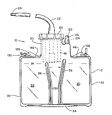
Referring to the drawings Fig. 1 shows a -thoracic
drainage unit 10 constructed of a relatively rigid
transparent plastic and including a container 12 having
a three compartment fluid collection chamber 14 and a
liquid seal chamber 16 located ;n an upper por-tion 50
of the container 12.
An inlet tube 22 opens into the liquid seal
chamber and is adapted for connection to a thoracic
drainage tube 24.
The collection chamber 14 is divided by partition walls
36,38 into compartments 26,28, and 30. Walls 36 and 38
are preferably formed by folds ;n the peripheral wall
32, as shown in Fig. 1. A septum connecting the
chambers may run down the lateral centreline oE the
container; this prevents undue flexing.
The partition 36 is somewhat shorter than the
partition 38 and both par-titions have V-shaped upper
edges. In use, body fluids firs-t accumulate in the
middle compartment 28; eventually the fluids overflow
into compartment 26 and finally -the fluid rises
sufficiently to overflow ;n-to compartment 30 -thereby
filling the entire con-tainer. The container 12 also
has upper walls 46 and 48 and an upwardly extending
tubular wall 50 with an opening 52 to receive the
liquid seal assembly 16. The opening 52 is round and
has external threads for cooperation with a closure
ring 53. The liquid seal assembl.y 16 and the baffle
assembly 54 positioned there;.n are assembled as
1~9;~3~
S-7085
--7--
a unit for insertion into the opening 52.
The details of l;quid seal chamber and -the
associated baffle assembly 54 are shown in Figs. 2-6.
The liquid seal assembly 16 ;ncludes circular wall 56
closed at the bottom by wall 58. The upper edge of the
wall 56 has an outwardly extending annular flange 60
which is embraced by a circular seal 62. The seal is
forrned by connected portions 64, 66 and 68 as shown in
figs 2A ~ 2B. The bottom wall 58 of -the assembly 16
has a central opening 70 in wh;ch an upstanding
overflow tube 72 is positioned; the tube protudes
slightly below the wall 58 as shown.
The baffle assembly 54 (fig 3) extends downwardly
into the chamber 16 and has an upper closure wall 20
which abuts the seal 62. The assembly 54 includes a
depending curved wall 82 comprising parallel wall
portions 84 and 86 and curved wall portions 88 and 90
(Fig 4) which extend from opposi-te s;des of a vertical
tube 92. The tube 92 extends downwardly from -the wall
20 and terminates between the bo-ttom wall 58, and the
upper open end of -tube 72 as shown.
An upright wall 96 is attached to the outer side
of tube 92; the side edges of wall 96 are beveled to
make surface contact with the inner face of the chamber
wall 56 when -the baffle assembly is inserted in -the
chamber. The lower end of the wall 96 is connec-ted to
an outwardLy and downwardly sloping wall 98 which also
has ;ts edges shaped to make contact with inner surface
of the wall 56. As will be described below the walls
96,98 establish a liquid Eree space so that the tube 92
can be seen through wall 56. The wall 98 ;s shown
braced to the tube 92 by another wall por-tion 100.
3~
S-7085
-8-
Referr;ng to Fig. 4, it can be seen that the
spaced wall portions 84 and 86 also extend to engage
the wall 56 so as to form a substantially enclosed
space -therewith;n. The wall portions 84 & 86 are cut
away at their lower edge as shown treference numeral
102). The cut away portions are below the upper open
end of tube 72.
Openings 106 are formed in walls 84 and 86 near
the upper ends thereof as shown in Fig. 5, and
depending V-shaped baffles 108 are mounted on either
side of the baffle assembly 54. The baffles 108 are
similar and ex-tend away from -the respec-tive openings
106 for contact with the wall 56.
The upper wall 20 of the baffle assembly 54 has a
locating lug 110 which cooperates with a notch 112 in
the wall of the seal chamber 16. In like manner, the
seal chamber 16 has a triangular lug 114 which
cooperates with a locating no-tch 116 (Fig. 6) in the
neck portion of -the main container 12. The locating
lugs and assoc;ated notches ensure that the main
containiner 12, seal chamber 16 and baffle assembly 54
can be quickly assembled in -the correct orientation.
The upper wall 20 of the baEfle assembly 54 has a
tubular inlet fitting 18 which is shaped -to receive one
end of an inlet hose 22, the opposite end of which is
connected to a thoracic drainage catheter.
In use, the seal chamber l6 and baffle assembly
54 are inserted into the container neck 50 and re-tained
by the closure ring 53; the seal 62 ensures a good
air-tight closure for operation under suction.
S-7085
_ g_
The container 12 has a tubular outlet fitting 124
extending upwardly therefrom and which can be closed by
a cap 126. A vacuum l;ne (not shown) can be attached
to the fitting 124 to ass;st ;n drawing fluids from the
body cavity. The fitt;ng 124 provides a vent when
drainage is under gravity.
The con-tainer 12 also has hooks 128 and/or a
strap 130 for hanging the device in a convienent
location. Alterna-t;vely the container 12 can s-tand on
a flat surface below the level of the patient.
Stability of a free standing container can be improved
by using transverse bracing members which fit into the
slo-ts formed by par-tition walls 36, 38. Such members
may be wire or flat plastic supports which extend
outwardly from the container.
On the front portion of the liquid seal chamber
16 are a plurality of spaced lines 132 which provide a
visual indication of the level of liquid ;n the seal
chamber 16. The level should be maintained high enough
to establish -the necessary liquid seal taking into
account the conditions of use. Liqu;d from the pat;ent
can accumulate in -the chamber 16 until the liquid level
exceeds the height of tube 72 whereupon it overflows
into the central chamber portion 28 of the ma;n
conta;ner 12.
The lower end of the inle-t tube 92 is cut away on
the outer side so that a space is formed between the
lower front edge 13~ and bottom wall 58 of the chamber
16. This facilitates drainage of incoming fluids and
permits the inner s;de of the tube 92 to complete the
baffle wall 82.
~ Z3~ S 7085
-1 O-
In a preferred embodiment the outer por-tion oE the tube
92 is cut away by about 9-13mm (,3 to 2 inch) as
measured from the bottom wall 58, a distance that is at
least as large as the inside diameter oE -the inlet tube
92. The sloping wall 98 is located somewhat above the
open lower tube end 134 -to prevent incoming fluids from
splashing and making it difficult to observe the
operation of the device.
When assembled into the liquid seal chamber 16,
the curved wall portions 88 and 90 of the baffle extend
all the way to the bottom wall 58 of the chamber 16
while the parallel baffle walls 84 and 86 are cut away
to prov;de fluid communication on opposite sides
thereof. The openings 106 communica-te with the
interior of the baffle and serve mainly as outle-ts for
the gases that may be present. This provides expansion
space for the gases which space also communicates
through the baffle assembly 54 and through -the ou-tlet
tube 72 to collection chamber 14.
The baffles 108 are intended to deflec-t rising
substances which may block the openings 106. The outer
edges of the baffle assembly 54 are bevelled to make
contact with -the inner surface of the chamber 16.
Generally the outer surfaces of the baffle assembly fit
closely with the inner surface of the chamber 16 but do
not necessarily provide a fluid -tight seal
therebetween; seals are not required between all of the
adjacent surfaces for the device to operate but it is
desirable to substantially reduce or to prevent the
passage of foam between the various baffle chambers and
-to d;rect liquid -to the open;ngs prov;ded in the lower
portions of -the chamber 16 and gases to -the upper
openings 106.
` ~Z9~3~
S-7085
The relatively close fit of adjacent walls is
sufficien-t -to prevent solid and semi-solid substances
or foams moving therebetween.
In use, it has been found desirable to coat the
baffle assembly 54 w;th a medical antifoam solution
which prevents undue buildup of foamed liquid at, for
example, the gas openings 106. The coa-ting also
prevents foam buildup which might deple-te the liquid
seal. A suitable antifoam solution comprises Dow
Corning Medical Grade Antifoam A dispersed in a
volatile solvent such as a Freon or me-thylene chloride,
a preferred volatile solvent being Freon TF of E.I.
Dupont de Nemours and Company. A suitable solution
concentration ranges from about 4% to about 10% of the
Antifoam A dissolved in from about 90 to about 96% by
weight of solvent. The baffle assembly 54 is dipped in
this solution un-til coated up -to the lower surface of
-the cover 20 and the solvent is allowed to flash off,
either at ambient conditions or in a low temperature
air recirculat;ng oven. The coating of the an-tifoam
agent remaining on the baffle assembly 54 is very
effective in preventing the bu;ldup oE pers;stent foam
in the liquid seal chamber 16 and this is true even
under continuous bubbling of the gases -through the
liquid seal. As noted above the s;ze and ex-tent of
such air bubbles which can be viewed ;n the sub~ect
device affords an easily monitored indication of the
patient's respiration conditions. The ant;foam agent
also acts to preven-t prema-ture depletion of the l;qu;d
seal due to bubbles generated by drainage of a patient
pneumothorax or bloody haemorrhage which can cause
ex-tensive bubbling and persistent foaming in the liquid
seal chamber 16.
Fig. 6 shows the manner of assembling the
separate portions of the present drainage device.
3~3
S-7085
-12-
Firstly the liquid seal chamber 16 ;s seated in the
neck portion 50 of the container 12, with elastomeric
sealing ring 62 in place about its upper edge. Correct
orienta-tion is ensured by the lug 114 and -the notch
5 116. Secondly, the baffle assembly 5~ is positioned ;n
the l;quid seal chamber 16, correct orientation being
ensured by lug 110 and notch 112. Finally, the cap 53
;s screwed onto neck 52 to seal the periphery of lid 20
tightly against the ring 62. The cap 53 also bears on
the upper edge of the neck 52 and if desired another
sealing ring 120 can be provided in the cap. The inlet
hose 22 ;s attached to the inlet fitting 18 and to a
drainage tube from the patien-t.
All parts of the present device are preferably
constructed of a transparent and relatively rigid
plastic material such as transparen-t butadiene styrene
copolymer, acetate butyrate styrene copolymer or a like
substance. When constructed of a relatively rigid
plastic material the volumes of the various chambers do
not vary substantially even though the pressure inside
may vary somewhat due to the patient s respiration or
the effect of the suction source. If all the various
walls are made of a transparent ma-terial it ;s possible
for an attendant to see into tube 92 and inspect the
body fluids and gases being drained from the body
cavity.
Before use, the user will precharge sterile water
or a saline solution into the liquid seal chamber 16
sufficien-t to cover the open lower end of inlet -tube
92. The chamber may be charged through -the inlet
fit-ting 18 or, if desired, through a separa-te orifice
which can be closed by an elastomeric plug. In the
preferred embodimen-t 60 to 85 ml of liquid is required.
~ 3~ S-7085
In use fluids pass from the pa-tient through the
inlet tube 92 ;nto the liquid seal chamber 16. L;quids
overflow through t.ube 72 into -the main collect;on
chamber 14. Gases also pass through tube 72 and thence
through outlet 124 to atmosphere or to -the suction
source.
Foam is generally confined to the space between
the outer wall of the baffle and the inner wall of the
seal chamber. The walls 96 & 98 ensure that the view
of inlet tube 92 ;s undes-truc-ted by foam; the rise &
fall of liquid can thus be observed. Bubbling of gas
through the liquid seal can be observed directly
through the wall 56.
If the unit is knocked over or even upended,
liquid in the water seal chamber cannot be lost since
the only exit is through outlet tube 72 which will
inevitably lie above the free surface of the liquid.
Results of tests are given below.
It has been found that this -thoracic drainage
unit provides effective and rela-tively long term
collection and measuremen-t of fluid drained from a
patient's pleural cavity and it does so with minimal
r;sk to the patient; -the fluid passages remain
relatively free from blockage. The free flow of fluid
and the liquid seal maintained thereby is fur-ther
assured by the size and nature of the various passages
and parts provided therefor. It can be seen Erom the
drawings that the cut away at the lower end of inlet
tube 92 is at least as large as ;ts diameter and that
the cut outs 102 in the baffle walls 84 and 86 as well
as opening 94 at the top of the overflow tube 72 are
all larger in size -then the diameter of -tube 92. This
means that anything that can enter from the pa-tient
shoul.d encounter easier passage at it moves through -the
liquid seal chamber.
S-7085
-14-
Furthermore, no tortuous or convoluted passages
are present which migh-t become blocked by such
substances.
In tests conducted with the thoracic drainage
unit described a positive liquid seal of at leas-t
12.5mm depth was maintained when the unit was tipped
forward whilst essentially no loss at all of the liquid
seal occured when the uni-t was tipped to either side or
backwards. In the drainage unit a liquid seal 12.5mm
deep was maintained even under tidaling of as much as
600 mm in the inlel tube 92 and connecting tube 22. In
extended tests the liquid seal retained its integri-ty
in all practical tests.
Under tests of simulated multi-hour dra;nage and
s;mulated pneumothorax the present thoracic drainage
unit performed in a fully satisfactory manner. Gravi-ty
drainage was maintained throughout a 72 hour test
employing a total of 2500 ml. of sanguinous fluids
starting with 500 ml of whole blood followed
successively by 500 ml of 75% whole blood and 25%
plasma, 500 ml of 50% whole blood and 50% plasma and
1000 ml of 25% whole blood and 75% plasma with a flow
rate diminishing exponentially from 200 ml/hour to 2
m]./hour at 72 hours. Blood clots of up to 10mm by 20
- mm in area and 3 mm thick were added a-t intervals
during the tes-t. The simmulated respira-tion volume of
6000ml/ minute for half of each 6 second cycle was
maintained freely throughout the test. The liquid seal
was continously maintained for the entire period. The
addit;on of blood clots had no apparent effect since no
blockage occurred.
S-7085
Similar excellen-t results were ob-tained in a
simulated ~8 hour medias-t;nal drainage test under -20
cm water vacuum and no air flow, wherein 2500 ml of
whole blood was employed at an initial flow rate oE 400
ml/hour diminishing exponentially to 0.9 ml/hour.
Blood clots of similar size as above described were
added at intervals throughout the test with no apparent
effect on fluid or air flow rates. The liquid seal was
maintained throughout the test at the full 24 mm depth.
At -the end of the test a sudden pneumothorax was
simulated by applying vacuum of from 0 to -10 cm water.
Patient breathing simulated by a pos;tive 5 cm water of
pressure showed no deterioration in the full 6000 ml
/minute of air flow obtained in the initial grav;ty
drainage tests. No blockage or increased resis-tance to
fluid flow occurred as a result of the addition of
blood clots.
Thus, there has been shown and described a novel
thoracic drainage device which demonstrates all the
features and advantages sought therefor. It will be
apparent to those skilled in the art after reviewing
this description, however, that many changes,
mod;fications, variations and o-ther uses in
applications for the subject thoracic drainage device
in addition to those which have been disclosed, are
poss;ble and contemplated, and all such changes,
modifications, var;ations and other uses and
applications which do no-t depart from the spiri-t and
scope of the invention are deemed to be covered by the
invention which is lirnited only by the claims which
follow.