Note: Descriptions are shown in the official language in which they were submitted.
~.z~
TRAY CARTON END FLAP AUXILIARY SEALER
Field of the Invention
This invention relates generally to the closing and sealing
of the end panels of tray cartons. ~ore particularly, it relates to
the closing and sealing of the end panels of a tray carton which is
at the panel closing station at the time the packaging machine stops.
~ack~round of the Invention
Bottles, cans and carriers containing bottles or cans are
commonly packa~ed for shipment in tray cartons, which comprise a
bottom panel foldably connected to relatively short side and end
panels. In the packaging operation tray carton blanks are fed -to a
continuously operating packaging machine which moves the blanks at
high speed and at the same time introduces the articles to be
packaged and forms the cartons from the blanXs.
Part of the carton forming opera-tion consists of folding
the end panels of the blanks up against end panel flaps and gluing
the end panels to the flaps. This is conventionally done by
employing static foldin~ rails to gradually fold the end panels up
into proper posi-tion as the filled carton blanks move by. Glue is
applied just prior to the folding operation so tha-t the end panels
can be brought into contact with the end flaps before the glue
dries. When the machine stops ru-nning, however, the car-ton in the
closing and sealing station at the time is not fully sealed because
the carton will not yet have reached the station where the end
panels are brought into contact with the end flaps. By the -time the
machine starts up again the glue will have dried and the carton will
not hold together.
This problem has been recognized in the past and attempts
17
--2--
have been made to solve it. For examplel U.S. Patent No. 3,504,478~
issued April 7, 1970 to Dieter, discloses separate ¢losers or plates
for pushing the end panels up against the end flaps w~en the
pnuematic circuit involved is actuated. A-t the same time the frame
that holds the end flaps in their folded position must be moved away
in order to make room for the closer plates to operate. These
actions take place before the end panels have be~un to be folded up
toward the end flaps. This arrangement requires extra equipment
which is relatively bulky and which tends to require maintenance
itself. Further, it ta~es up space on the machine which otherwise
could be used Eor the basic tasks of feeding and fabricating the
tray cartons.
Another approach to the problem is disclosed in U.S. Patent
~o. 4,562,687, issued January 7, 1986 to Grsen, Jr., which discloses
the use of folding plates havin~ a component of movement in the
direction of travel of the tray cartons. The positive folding action
employed adheres the end panels of each tray carton to the end
flaps, includin~ the carton at the sealing station at the time of a
machine shutdown. While this approach eliminates the problem
discussed above, it requires moving parts to carry out the normal
folding and seaLing process and as such is subject to more equipment
maintenance and equipment failure. Further, ~reater machine speeds
are possible with stationary rail folders.
It would be desirahle to provide means for sealin~ the end
panels to the end flaps in a simple yet efficient manner which can
readily be incorporated in a conventiotlal tray carton packaging
machine .
~rief Summary of the Invention
This invention provides end panel folding means which can
be actuated for movement toward the end flaps of a tray carton when
the packaging machine stops running. The end panel folding means
comprises a stationary first means for folding the moving end panels
up from a flat unfolded position to an intermediate fol(Jed position,
normally stationary second means for maintaining the moving end
panels in their inteLmediate folded position, and stationary third
means for foldin~ the moving end panels up from their intermediate
folded position to their final folded position against the end
flaps. The normally stationary second means comprises guide plates
mounted for pivotal movement about horizontal axes toward and away
from the end flaps.
The normally stationary guide plates are part of the normal
folding operation of the end panels and are actuated to move the end
panels with which they are in contact up against the end flaps only
when the machine stops. Thus they occupy little extra space and do
not interfere with the ability of the packaging machine to operate
at high speeds.
Other features and aspects of the invention, as well as its
various benefits, will be made more clear in the detailed
description of the invention which follows.
Brief Description of the Drawin~s
E'IG. 1 is a plan view of a blank used in the fab~ication of
a conventional tray carton of the type to which this invention
relates;
FIGS. 2A-2E are sequential pictorial views of the folding
of the blank of FIG. 1 to form a tray carton;
E'IG. 3 is a schematic plan view of a portion of a packaging
machine for fabricating and filling tray cartons of the type shown
in FIGS. 1 and 2;
E'IG. 4 is an enlarged view of the folding and sealing
station shown in FIG. 3;
FIG. 5A is a sectional view taken on line 5~5 of FIG. 4
showing the normal stationary position of the plates which hold the
rnd panels in their intermediate folded pOSitiOtl;
PIG. 5s is a sectional view similar to that of FIG. 5A, but
showing the plates in their actuated position which holds the end
panels in contact with the end flaps of the tray carton;
IF:LG. 6 is a plan view, with some intervening structure
omitted for purpose of clarity, of the mechanism for actuating
movement of the plates of FIGS. 5A and 5B; and
FIGS. 7A-7C are pictorial views showing in sequence the
various sta~es of folding the end panels of the tray carton blank to
form a tray carton.
Description of the Invention
Referring to E'IG. 1, a typical blank 10 used -to form a tray
2~
--4--
carton i5 comprised of a bottom panel l2, side panels 14 connectefJ
to the bottom panel by fold lines 16 and end panels 18 comlec-ted to
the bottom panel by fold lines 20. Connected to the end portions of
the side panels 14 by fold lines 22 are end flaps 24.
A5 shown in E'IG. 2A, the side panels of the 'blank 10 are
first folded up along fold lines 16. The raised side panels form the
leading and trailing panels of the blank as it travels through the
packaging machine. Typically, the end flaps 24 at the entry end of
the carton, that is, the end through which the articles to be
packaged enter the tray, are then folded out as illustrated in FIG.
2B so as not to interfere wit'h the movement of the articles into the
tray. The other end flaps 24 are folded in as shown in FIG. 2B.
As shown in FIG. 2C the articles A are then introduced into
the tray and subsequently the end flaps 24 at the entry end of the
tray are folded in toward each other as shown in FIG. 2D. The end
panels 18 are then folded up against the end flaps, as shown in FIG.
2E, and adhered to them by glue. The filled tray carton is then
discharged from the packaging machine for fur-ther handling and
shipping.
Referring to FIG. 3, the packaging machine to which t'his
invention relates is indicated generally at 26 and comprises a
carton blank hopper and feed station 28, a carton conveyor 30, an
article infeed conveyor 32, and a basket c'hain conveyor 34.
Overlying a portion of the basket chain conveyor 34 is a pusher
plate conveyor 36. The operation of the machine to this point is
convelltional. Articles are delivered to the infeed conveyor 32 and
are deposited by the infeed conveyor onto the basXe-t chain conveyor
34. The articles may be single articles such as individual beverage
bo-ttles or cans or they may be larger units of such ite.ms, such as
carriers holding six or twelve bottles or cans. In either case the
speed of the article infeed conveyor is related to the speed of the
basket chain conveyor 34 so that the desired number of articles to
be packaged in a tray carton are loaded into each section 38 of the
basket chain conveyor. Each section of the basket chain conveyor is
separated from adjacent sections by bars 40 which are raised above
the slatted surface of the basket chain conveyor. The pusher plates
42 are mounted on a continuous chain ~l4 of the pusher pla-te conveyor
- ;~2~ 17
36 which is angled with respect to the direction of movement of the
infeed conveyor 32 and the carton conveyor 30. The faces of the
pusher plates which contact the articles are parallel to the
direction of movement of the infeed conveyor and the car-ton conveyor
so that continued movement of the pusher plates 92 eventually pushes
the articles off the basket chain conveyor 34 and onto the carton
conveyor 30.
The carton conveyor 30 includes spaced support surfaces
31 located between endless chains 46 which carry lugs 48 at spaced
intervals corresponding to the width of a tray car-ton. The lugs 48
not only push the cartons downstream, but also serve to fold up the
side panels of the tray carton blank to the position shown in FIG.
2A. In addition, the lugs 48 and the separator bars 40 on the
basket chain conveyor 34 cooperate to hold the end flaps 24 located
at the article entry end of the carton conveyor 30 in the folded-
back condition shown in FIGS. 2B and 2C. The end panels 18 ride
beneath hold-down bars 50 which maintain -the end panels in the flat
unfolded position shown in FIGS. 2A-2D, and -the flaps 24 on the side
of the carton opposite the entry end are maintained in their closed
folded-in position shown in FIG. 2B by flap retaining rod 52.
The tray blank hopper and feed section 28 can be of any
specific design desired. For example, it can function in the manner
of the system disclosed in U.S. Paten-t No. 4,034,658, issued July
12, 1977, to Sherman. The other features oE the packaging machine
described -thus far are explained in more de-tail in the
aforementioned U.S. Patent No. 4,562,687.
The machine of FIG. 3 also consists of a gluing and
sealing station 59. The end panels 18 of the carton are folded up
to an intermediate point just pri.or to reach:i.ng the gluing station,
then after leaving the station they are folded up against the end
flaps and held in place by compression bars 56. The compression
bars 56, which may comprise any acceptable design of the prior art,
are set so as to exert pressure on the ends of the carton for a
predetermined distance as the cartons are moved by the carton
conveyor 30 downstream from -the gluing and sealing station 54. By
the time the tray cartons exit from the compression bars the glue
~. '
Z~17
--6--
will have been dried and set and the carkons wilL be structurally
sound. The cartons then continue downst,ream on the conveyor 30 to a
pOillt, not shown, where they are discharged for further handling.
Referring now to FIG. 4, as the filled part:ially erected
cartons of FIG. 2C move downstream on the conveyor 30, the leading
end flap 24 on the entry side of the carton will contact stationary
flap folding rod 57 and be folded thereby bac'k toward the traili.ng
side panel 14. A finger 58, connected to rotating shaft 60, is
adapted to rotate in a counterclockwise direction so as to strike
the trailing end flap on the entry side of the carton and fold it
forward toward the leading side panel. The trailing end flap will ~e
exposed to the finger 58 at this point because it will have passed
downstream from the basket conveyor 34 and will therefore no longer
be held by the lugs 48 and the separator bars ~l0 in its folded-back
position. The trailing end flap will be retained in its new
folded-in position by the flap folding bar 57, and the filled carton
at this point will correspond to the carton of E'IG. 2~. The shaft 60
may be mounted for rotation in suitable journals 62 and may be
powered through any convenient power train, such as by a drive shaft
64 connected by a sprocket 65 and chain 66 to a sprocket 68 attached
to the shaft 60.
Situated slightly down~tream from the end of the flap
folding rod 57 on both sides of the conveyor 30 are static end panel
folding bars 70 of conventional shape well known in the art. The
function of the folding bars 70 is to initiate the upward folding of
the end panels 'l8 so that the end panels are in an intermediate
folded condition as the carton enters the gluing station 54. The
action of the foldlng bars 70 is illustrated in FIG. 7A, wherein the
downstream portions of the end panels are shown in their
intetmediate position while the upstream portions of the end panels
are shown in t'he initial stage of being folded upwardl,y by the bars
70.
Still referring to FIG. 4, continued movemenk of the
conveyor carries the carton into the gluing station 5~l where plates
72 support and guicle the end panels 18 to maintain them in the
intermel~iate folded position established at the downstream end of
the folding bars 70. The end panels receive adhesive while in the
~2~
--7--
gluing station 54 from glue heads 7~l located above the plates. The
adhesive, which may be of any type suited ~or such an operation and
is preferably of the hot melt type, is sprayed on the leading and
trailing portions of the moving end panels so that it is located
opposite -the folded end flaps. The carton is shown while supported
by the plates 72 during the not~lal continuous operation of the
packa~ing machine in FIG. 7B.
As the carton leaves the gluing station 54 the end panels
18 come into contact with static folding bars 76, which are designed
to continue and complete the folding of the end panels up agains-t
the end flaps 24. The carton at this stage is illustrated in FIG.
7C, wherein the downst~eam end of the end panels has been folded
into contact with the end flaps but the upstream end is just in the
process of being engaged by the upstream end of the folding bars 76.
1S The adhesive on the end panels contacts the end flaps and the
compression bars 56, as mentioned above, hold the end panels against
the end flaps a sufficiently long time to allow the glue to set to
permanently adhere the end panels to the end flaps.
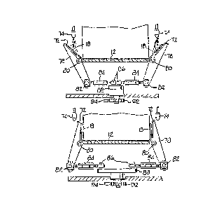
Referring to FIG. 5A, the plates 72 are shown supporting
the end panels 18 in the intermediate position illustrated in FIG.
7B, which is the normal operating position of the plates. As shown
in both FIGS. SA and 6, each plate 72 is supported at each end by a
pair of spaced arms 78. The arms 78 are pivotally mounted in their
central portions about horizontal axes 80 and are pivotally attached
at their lower ends at 82 to links 84. The central portions of the
links 84 are illustrated as comprising turnbuckles for purpose of
adjustment. The opposite or inner ends of the links 84 are pivotally
connected at 86 to the opposite ends of a plate 88 which is mounted
on vertical shaft 90. Connected to the 1m-3erside of the plate 88 is
a pinion gear 92 also mounted on the shaft 90. The pinion gear 92 is
operatively cotmected to a rack 94 which may be actuated for
reciprocal movement by any desired means but preferably is powered
by any o~ the well known types of pneumatic rotary actuators. The
rotary actuator will cause movement of the rack 94 which will cause
the pinion gear to rotate, in turn causing the plate 88 -to ro-tate.
The links 84 are thus caused to move the bottom ends of the arms 78
inwardly or outwardly, depending on the direction of rotation of the
1~9~'~17
--8--
plate 8~. When the plate 88 i5 rotated from the normal operating
position shown itl E'I~. 6, t'he lower ends of the arms 7~ are moved
outwardly, causing the upper portions of t.he arms to move the plates
72 into the vertical position shown in FIG. 5B.
S In operation, when the machine is shut down the rotary
actuator or other rack drive means is actuated through suitable
circuitry, not shown but well known in the art, causing movement of
the rack ~4 and the pivoting or rotation of the plate 88. This
results in the upward pivoting of the guide plates 72. Note that as
the plate 88 moves from the F'IG. 5A position to the FIG. 5B
position, the outer ends of the links 84 move very lit-tle in an
outward transverse direction compared to the movement of the plate,
producing a slow final closing movement of the plates 72 of great
mechanical advantage. This gives sufficient time for the carton in
lS the gluing station to settle to its final resting position after its
downstream movement stops before the pla-tes 72 contact it to press
the end panels up against the end flaps. Because the end panels will
have been coated with adhesive the forceful and sustained contact
between the end panels and the end flaps will result in the bonding
together of the end panels to the end flaps. The carton in the
sealing station at the time of shutdown will therefore not escape
the gluing operation but will eventually emerge f~om the machine as
a structurally intact carton.
The problem of carton failure due to the inability to seal
the last carton to be glued prior to a machine shutdown has thus
been overcome by the present invention. ~y making use of normally
static guide plates to move the end panels into contact with the end
flaps upon a machine shutdown, -the mac'hine length has been kept to a
minimum and the distance the guide plates have to move has been
minimized. With ~uch short listances to move and with the simple
actuatillg mechanism employed, the guide plates move immediately and
very powerfully upon machine s'hutdown, resulting in a highly
efficient, low maintenance arrangement.
It should be obvious that although a preferred embodiment
of the invention has been disclosed, changes to certain of the
details of the embodiment can be made without departing from the
spirit and scope of the invention as defined in the claims.