Note: Descriptions are shown in the official language in which they were submitted.
TR~Y FOR T~NSPORTING ~NT~RN~L COMBUSTJON ENGIN~ PISTONS
BACKGROUND OF THE INVENTION
ll
1. Field of the Invention:
This invention relates to a tray for transporting
internal combustion engine pistons. The tray is reusable.
The tray includes first and second concentric pockets for
receiving pistons having different diameters.
2. Prior Art:
In modern manufacturing, it is common practice to
assemble completed units at a single location from various
parts and components which are shipped to the assembly
location from other locations. The parts and components are
normally fabricated in facilities remote from the assembly
location and shipped to the assembly locations in containers.
Internal combustion engine pistons have commonly been
transported in relatively large containers wherein the
pistons are stacked in layers and separated by means of
corrugated cardboard dividers, commonly with the further use
of corrugated sheets between the layers. The use of
corrugated cardboard has provided protection against damage
to the pistons, portions of which are highly finished.
However, this practice has not resulted in efficient space
utilization and has resulted in a disposal problem, it being
necessary to dispose of the corrugated cardboard material as
the containers have been emptied of pistons.
In accordance with the present invention a reusable
tray for transporting internal combustion engine pistons is
.~ 7~
provided. The tray 18 fabrlcated of a plastic materlal which
is of relatlvely high strength but has a relatively soft and
s~ooth surface and is flexible. Suitable plastic ls, for
example, a high impact styrene. The construction of the tray
is adapted to prevent scratching, gouging or like damage to
pistons during storage and transport. Pistons are fabricated
as machined items and it is desired not to damage the
machined surfaces. In particular, it is highly desirable not
to damage the highly finished surfaces of the piston which
are the bearing surfaces for mounting the connecting rod
wrist pin. The tray of the present invention provides
separation of the pistons and also provides a smooth surface
for contact with the pistons which will not abrade or
otherwise damage the piston surfaces. The tray is reusable
and thus does not involve a disposal problem at assembly
points. The reusable nature of the trays results in ultimate
lower costs. The construction of the trays makes maximum
utilization of space.
SUMMARY OF THE INVENTION
A tray for transporting internal combustion engine
pistons is provided. The tray comprises a generally
rectangular tray body having a bottom wall. A plurality of
spaced apart generally cylindrical first pockets extend
downwardly from the bottom wall. Second pocket sidewall
structure extends upwardly from the bottom wall
concentrically around each of the first pockets to define a
plurality of spaced apart generally cylindrical second
pockets extending upwardly from the bottom wall.
~ t7~
~ he juncture of the sidewall structure with the
bottom wall i8 spaced a short distance from each of the first
pockets to define a first generally cylindrical shelf adapted
to support a piston. The first pockets include a sidewall
structure and a bottom wall. A second generally cylindrical
relatively narrow shelf is provided at the juncture of the
first pocket sidewall structure and bottom wall. The second
shelf is spaced from the first pocket bottom wall and adapted
to support a piston.
The diameter of the first pockets is less than the
diameter of the second pockets whereby pistons having one
diameter are receivable in the first pockets and pistons
having a second larger diameter are receivable in the second
pocketsO Both the second pocket sidewall structure and the
first pocket sidewall structure are angled inwardly of the
pockets from the upper to the lower portions thereof to
facilitate easy insertion and extraction of pistons.
The second pocket sidewall structures between sets
of four second pockets in the central portion of the tray and
the second pocket sidewall structures between sets of two
adjacent pockets positioned at the tray outer edges are
joined together by a top wall. Each second section pocket
side~all structure has gaps therein spaced about ninety
degrees apart and in diametric alignment with a gap of an
adjacent second pocket sidewall structure.
An upstanding tray sidewall structure extends
around the outer periphery of the tray. The tray sidewall
structure is indented at one point along each edge of the
tray to provide hand holds. The tray sidewall indentations
l'~S~7~'~
are positioned between pair6 of pockets. Each indentation is
sym~etrically offset with respect to the indentation on the
opposed tray sidewall to balance a tray load when lifted with
two hands.
BRIEF DESCRIPTION OF THE DRAWINGS
Figure 1 is a view in perspective of one preferred
embo~iment of the present invention;
Figure 2 is a top plan view of the tray of Figure
l;
Figure 3 is a side elevational view of the tray of
Figure l;
Figure 4 is a sectional view taken substantially
along the line 4-4 of Figure 2 looking in the direction of
the arrows;
Figure 5 is a sectional portion of the tray as in
Figure 4 illustrating loading of the trays with pistons and
stacking loaded trays upon each other;
Figure 6 is a view similar to Figure 5 illustrating
loading of the tray with pistons of smaller diameter than
those illustrated in Figure 5; and
Figure 7 illustrates the stacking of loaded trays
in a larger container for transportation and storage
pl~rposes .
- 4 -
'7~
DETAILED DESCRIPTION OF THE PREFERRED EMBODIMENT
Referring to the drawings, it will be noted that
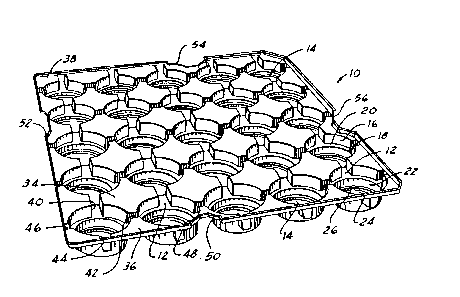
the tray 10 comprises a generally rectangular tray body
having a bottom wall 12. A plurality of spaced apart
generally cylindrical first pockets 14 extend downwardly
from the bottom wall 12. Illustratively, the pockets 14
are twenty-five in number. Second pocket sidewall
structure 16 extends upwardly from the bottom wall 12
concentrically around each of the first pockets 14 to
define a plurality of spaced apart generally cylindrical
second pockets 18 extending upwardly from the bottom wall
12.
The juncture of the sidewall structures 16 with
the bottom wall 12 is spaced a short distance from each of
the first pocket 14 to define a generally cylindrical
horizontally extending shelf 20 adapted to support a
piston. The first pockets 14 include a sidewall structure
22 and a bottom wall 24. A second generally cylindrically
horizontally extending narrow shelf 26 is provided at the
juncture of the first pocket sidewall structure 22 and
bottom wall 24. The second shelf 26 is spaced from the
first pocket bottom wall 24 by means of wall section 28.
The second shelf 26 is also adapted to support a piston.
As will be noted, the diameter of the first
pockets 14 is less than the diameter of the second pockets
18 whereby pistons 30 having one diameter as will be noted
in Figure 6 are receivable in the first pockets 14 and
pistons 32 having a second larger diameter are receivable
in the second pockets 18 as will be noted in Figure 5.
Both the second pocket sidewall structures 16 and the
first poGket sidewall structures 22 are angled inwardly of
the pockets from the
LCM:~ _ 5 _
., ,~
7~J,~
u?per port1ons to the lower portions thereof to facllitate
easy insertion and extraction of pistonq. This draft may be
noted in Figures 5 and 6 with reference to the piston
diameters.
As will be noted in Figures 1 and 2, the second
pocket sidewall structures 16 between sets of four pockets in
the central portion of the tray 10 and between sets of two
adjacent pockets positioned at the tray outer edges are
joined together by top walls 34 and 36 respectively. Corner
top ~all structures 38 are also provided. The provision of
the top wall structures functions to structurally reinforce
the tray 10.
Each second pocket sidewall structure 16 has four
gaps 40, 42, 44, 46 therein spaced about ninety degrees apart
and in diametric alignment with a gap of an adjacent second
pocket ~idewall structure (referencing the diameter of the
pocket). This results in a plurality of generally star
shaped structures having four points in the central portion
of the tray and half stars along the tray edges when the tray
is viewed from above. The provision of the gaps permits the
tray 10 to flex somewhat when it is lifted after being loaded
with ~istons while at the same time tray integrity is
maintained by the structure of the star shaped upper
structures and the cylindrically shaped lower first pocket
structures.
An upstanding tray sidewall structure 48 extends
around the outer periphery of the tray 10. The tray sidewall
structure 48 is indented at one point 50, 52, 54, 56 along
each edge of the tray to provide hand holds. The tray
1.'~(!'~'7~
sidewall lndentat~ons 50, 52, 54, 56 are pos1t~oned between
pairs of pockets. Each indentat~on6 is symmetrically offset
with respect to the indentation on the opposed tray sidewall
structure to balance a tray load when lifted with two hands.
For example, indentation 50 is offset symmetrically with
respect to indentation 54 while indentation 52 is offset
symmetrically with respect to indentation 56.
As previously mentioned, loaded trays may be
stacked one upon the other as shown in Figures 5, 6 and 7.
Figure 5 illustrates loading of a tray with larger diameter
pistons 32. As will be noted, the larger diameter pistons
are received on the first cylindrical shelf 20 and do not
extend into the first pockets 14. On the other hand, the
smaller diameter pistons 30 indicated in Figure 6 do extend
into the first pockets 14 and are received on the second
shel~es 26. The tray 10 may, in addition to the two
different diameter sizes shown, accept pistons which vary in
height. As shown in both Figures 5 and 6, one tray 10 loaded
with pistons may be stacked upon a lower or subjacent tray
also loaded with pistons. In stacking of loaded trays, the
bottom of the first pockets 14 rests upon bosses 58 of larger
pistons 32 shown in Figure 5 which are provided interiorly of
the piston with center bores 60 to receive wrist pins to
retain piston connecting rods. The pistons are provided with
upwar~ly extending skirt portions which define ears 62, 64.
The ears 62, 64 extend around the first pockets 14 and
stabilize stacks of loaded trays. In the case of small
diameter pistons 30 as shown in Figure 6, the lower surfaces
of the shelves 26 rest on the piston ears. As shown in
Figure 7, loaded trays are conveniently stacked within a
larger container 66 for shipment and storage purposes.
~ t~
Representatlvely, four 6tacks of loaded tray~ are recelved ln
the container 66 and are stacked eight hlgh.
As previously mentioned, the tray 10 is fabricated
of a plastic material, as for example, high impact styrene.
This material results in adequate strength for loaded trays
while at the same time being relative flexible to permit some
flexing of a loaded tray when it is lifted to thus prevent
cracking. The outer surfaces of the pistons are not damaged
by t~e smooth surface of the plastic material.
I Claim: