Note: Descriptions are shown in the official language in which they were submitted.
~Z9ZE~50
TITLE
SEAMLESS LAMINAR ARTICLE
~ACKGR~UND OF THE INVEN'lIO~
Field of the Invention
This inventior relates to thermoplastic
articles malded from a heterogeneous blenu of
incompatible polvmers. Especially preferrea poiymers
are a polyolefin first polymer anù a secona ~olymer,
incompati~le with the polyolefin. Tne invention,
additionally, relates to processes for making such
articles. The invention specifically relates to suc~
articles having substantially uniform wall
thicknesses around the circumference of a g~nerally
cylindrical shape with resulting improvea barrieL
properties and strength.
Description of Prior Art
U.S. Patent No. 4,410,482 discloses
manufacture of thermoplastic articles from a
heterogeneous blend of a polyolefin first polymer anù
an incompatible second polymer. The articles o~ that
patent have the polymer components present as a
multitude of thin, substantially two-dimensional,
parallel and overlapping layers and such art~cles in
the form of containers are aisclosea to exhibit
permeation barrier characteristlcs greatiy increase~
in comparison with containers made fron, pol~olefin,
alone. Other patents which aisclose articles havlng
a similar construction incluae U.~. Patents No.
4,444,817 and 4,416,94~.
U.S. Patent No. 3,~99,8~ aiscloses an
extrusion device for making tubing of homogeneous
wall construction whereoy molten moldiny material is
conducted through the device by streamlining su~port
fins to reduce the existence of flow lines causea by
9D-5441 35 separation of the material in the so-called nozzle
~Z92850
head. This patent also discloses a steplike offset
of the support to assure effective mixing of the
molten material.
U.S. Patents No. 3,~79,501 and 3,404,~03
disclose manufacture of tubing with orientea internal
and external surfaces wherein the mold surfaces are
counter-rotated during extrusion of the molten
material.
U.S. Patent ~o. 3,~56,560 discloses a di~
for orienting the internal anc external surfaces of
an extrudate by means of grooves cut in the
respective surfaces of the die to direct the flow of
molten material in opposite directlons.
SUMMARY OF THE INVENTIG~
According to this invention there is
provided a process for manufacturing a lan,inar,
molded, hollow, article of polymeric materla
comprising the steps of establishing a molten,
heterogeneous, blend of incompatible polymers by
heating the blend above the melting point of the
highest melting polymer component and, then, molaing
the melted blend by extruding a body of the blend
through a die wherein internal surfaces of the die
have streamlined irregularities positioned to
~isplace surface material of the blend relative to
core material of the blend and cooling the extruaed
body to below the melting point of the lowest meltins
polymer component. In a preferre~, continuous, blow
molding process of this invention, the extruaea boay
is blown before cooling. The blend o~ incompati~le
polymers preferred and most often usea incluaes a
polyolefin as a continuous or matrix phase ana a
second polymer incompatible with the polyolefln as a
discontinuous or distributed phase.
~z9~
A laminar, moldea, hollow artlcle is also
- provided which comprises a combination of
incompatible polymers wherein the polymers are
present as thin, substantially two-dimensional,
parallel ana overlapping layers of material and
wherein melt seams or knit lines in the artlcle are
c~rved to provide such overlapping layers in any
radial section through a wall of the hollow article.
Such laminar hollow article, when blow molded, has
overlapping layers in any radial section and has
walls of substantially uniform thickness around the
perimeter or circumference of the article.
An important and critical aspect of the
present invention resides in the aisplacement of
surface material during manufacture of articles
molded using the heterogeneous blend such that, when
the blend is stretchea, all components of the blen~
remain relatively uniformly distribute~ throughout
the article and the thickness of the article does not
undergo thinning at one area out of proportlon with
other areas of the article.
BRIEE DESCRIPTON OF T~ DRA~lNGS
Fig. 1 is a cross-sectional representatlon
of an extrusion device with a grooved spiral head
useul for practicing the present invention.
Fig. 2 is a cross-sectional representation
of an extrusion device with a rotating extrusion heao
useful for practicing the present invention.
Fig. 3 is a cross-sectional representation
of a ribbed spiral head to be used in an extrusion
~evice for practice of the present invention.
Fig. 4 is a cross-sectional representation
of a blow mol~ed lamellar container wall of the prior
art displaying a greatly magnifiea melt seam volume.
129Z850
Fig. 5 is a cross-sectional representation
of a blow molded lamellar container wall of the
present invention having one wall surface displacea
and displaying a greatly magnified melt seam volu~,e.
Fig. 6 is a cross-sectional repr-esentation
of a blow molded lamellar container wall of the
present invention having two wall surfaces aisplacea
and displaying a greatly magnified melt seam voiume.
DESCRIPTION O~ E I~iVENl IOI~I
Laminar, shaped, articles are well known
which are maae from a n,ixture of incompatible
polymers wherein one polyn,er is in the form of a
continuous matrix phase and another polymer is in the
form of a discontinuous distributea phase. The
laminar articles are made by mixing together
particles of the polymers, heating the mixture to
yield a heterogeneous melt of material, an~ forming
the melt in a way which results in stretching the
melt to yielà an elongated discontinuous polymer
phase.
In one embodiment, the polymer partlcles, in
unmelted form, are mixed thoroughly so as to proviae
a statistically homogeneous distribution ana care is
exercised to avoid substantiai aaditlonal n,lxing
after the polymers have been heatea to a melt. lr,
another embodiment, the ~olymer particles can be
combined in softened or molten form so lons as the
combination of polymers maintains a heterogeneous
character. The blend can, also, be establishea by
combining the polymers such that the highest melting
of the polymers is not softened or molten and then
heating the combination. The success of the
invention depends on establishing a melted
heterogeneous blend of incompatible polymers so that,
when the melt is stretched, such as b~ blow molding
`` 12928S~)
forces, one polymer is in the form of a continuous
~atrix phase and another polymer is in the for~l ol a
discontinuous distributed phase. The polymer
comprising the discontinuous phase is present as a
multitude of thin, substantially two-dimensional,
parallel and overlapping layers embedded in the
continuous phase.
The thin, substantially two-dimensional,
parallel and overlapping layers operate, in concert,
to provide strength and permeation barrier qualitles
to the article so-formea. To the extent that the
layers overlap, the strength and the barrier
qualities are enhanced by providing a briage of
discontinuous material across the matrix phase.
The strengthening èffect o~ overlappeo
layers is especially pronounced in the manufacture of
laminar articles by blow molding means although the
effect is, also, exhibited when the laminar articles
are made by other means, such as by the stretching
forces which are associated with simple extrusion.
In blow molding manufacture of laminar
articlec, such as in blow molding bottles, a parison
is generally made and then the parison is ~lown to a
final bottle shape. Parisons are manufactured by
extrusion from dies which form tubing an~ sucr, oles
must be constructed with support elements or materiaï
flow components which divide the molten material as
it flows to the die lip opening. In the laminar,
heterogeneous, article of the present inventlon, an~
division of the molten material prevents overlap of
layers in the distributed phase at the points of
division and causes weakening of the article unless
the overlap can somehow be reinstitute~.
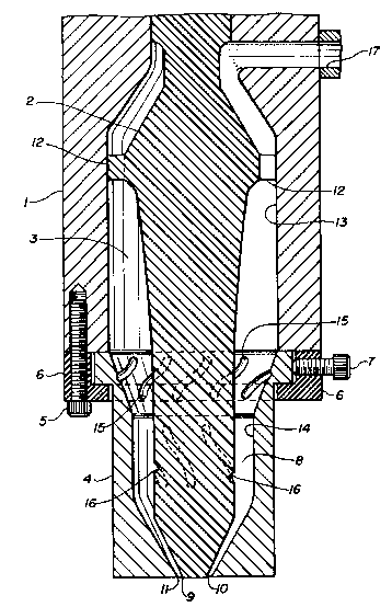
Fig. 1 depicts an extrusion device with a
body 1 and a mandrel 2 centrally positioned within a
--` 129Z850
cavity 3 in body 1. Outer die lip element 4 is
affixed to body 1 by means of bolts 5 and ring 6 and
its position is adjusted by means of bolts 7. Outer
die lip element 4 includes a cavity 8 in which
mandrel 2 is also centrally positioned. Mandrel ~
ends in an inner die lip surface 9 at the point where
mandrel 2 is in closest proximity with exit 10 from
outer die lip element 4 to form outer die lip surface
11. Mandrel 2, centrally located in cavities ~ ana
8, are supported by spiders 12 which are rigid struts
from about two to twelve in number arrangea
equidistant from each other fixea between manarel
and the inner wall 13 of boay 1. In Fig. 1, two of
the spiders 12 are shown. One spiàer 12 is shown in
cross section as a part ol mandrel 2 ana another
spider 12 is shown as it radiates from manarel 2 into
the plane of the figure to boay 1. ~xtrusion aevices
5uch as are depicted in Fig. 1 and in Fig. ~ are
often used without spiders but are shown here to
afford the aaded stability provided thereby.
The inner wall 14 of outer die li~ element 4
has grooves 15 which serve as streamlined
irregularities for spirally displacing molten
material passing through the device. l~he manarel 2
may have grooves 16 which, also, serve as streamlinea
irreaularities for spirally displacing molten
material. Grooves 15 and 16 are, generally, locatea
with opposite spirals.
In operation, a molten, heterogeneous, blend
of incompatible polymers is intro~uced into the
extrusion device through iniet port 17 ana arouna
mandrel 2. The molten material passes arouna both
sides of mandrel 2 and where the material meets
itself on the side opposite the inlet port 17, a knit
line is formed. The knit line is so-callea because
lZ928~0
the molten material must knit together an~ forn, a
weld or joint in the final moldea artlcle. ~ithout
the benefit of the present invention, the continuous
or matrix phase of the heterogeneous blena of
polymers can be successfully knit together; but the
discontinuous or distributed phase cannot ~orm an
adequate joint because the parallel layers of
distributed material cannot overlap across the knit
line.
The molten blend, complete with knit line,
continues into cavity 3 ana passes spiders 12
whereupon the blend is cut by each of the spiders
12. At each cut, the molten material is separated;
an~, after each spider, the molten material is
rejoined with itself and results in a melt seam
wherein the continuous or matrix phase is
successf~lly joined but the distributed phase is not
overlapped across the seam.
The molten blend, with knit line ana melt
seams, advances through cavlty 3 and into cavity 8.
For purposes of describing this lnvention, knit llnes
and melt seams are equivalent ana either designation
can be taken to mean both. At cavity ~, the molten
blend encounters streamlined irregularities in the
form of grooves 15 in outer die lip element 4 an~
orooves 16 in mandrel 2. ~he grooves 15 and 16 are
spirally placed in opposing directions on outer ~le
lip element 4 and mandrel 2, res~ectively, and the
grooves cause gentle displacement of surface layer~
of the molten material such that the melt seams are
curved and particles of the distributed phase are
overlapped in the sense that such particles are
present in any radial section through the molten
material.
1292BSO
The molten blend, with displaced surface
layers, is extruded ~etween inner die lip surface 9
and outer die lip surface 11 to yield a shaped
article having curved knit lines ana overlapping
particles of the distributed phase. It shoui~ be
noted that the benefits of this inventlon can be
realizea even if the streamlined irregularities are
present on only one surface of the extrusion devlce,
for example, on only the outer die lip element 4 o~
on only the mandrel 2. Moreover, the streamllnea
irregularities can be locatea, generally, on any
surface of cavity 3 or cavity b so long as they are
aownstream from the spiders 12 and they can take the
form of either grooves or ridges.
Thè grooves or ridges -- the streamlined
irregularities -- should be shapea such that the
irregularities cause displacement of less than about
one-third of the thickness of the molten material on
the affected side and the displacement should be
géntle in that the displaced material is maintainea
in its heterogeneous condition and is not mixea
exce~sively, causing homogenization of the displace~
blend.
Fig. 2 depicts an alternative embo~iment of
an extru~ion devlce useful in practice of this
invention. l'he device comprises boay lb ana manarel
19 with c~vity ~O in boày 1~. In thls aevice, outer
die lip element 21 is rotatably mounted agalnst booy
18 such that cavity 20 matches with cavity ~2 in
outer die lip element 21. Outer die lip element 21
is held against body 18 by means of bolts 23 ana ring
24 and rotatability is maintained by bearings 2~.
Seal 26 is providea to prevent leakage of molten
molding material. Outer die lip element 21 has rlng
gear 27 mounted thereon and it is rotated by drivlng
12928SO
gear 28. A molten, heterogeneous, blend of
incompatible polymers is introduced at inlet port ~,
forms a knit line at mandrel 19, and traverses the
cavities 20 and 22 being separated during its travels
b~ spiders 30 and then rejoined. In Fig. 2, two of
the spiders 30 are shown. One spiaer 30 is shown in
cross section as a part of mandrel 19 ana another
spider 30 is shown as it radiates from manarel 19
into the plane of the figure to body 18. Outer aie
lip element 21 is rotated and the rotation causes
shear forces between the inner surface 31 of outer
die lip element 21 ana tne molten blend. In tt,is
case, the streamlinea irregularities can be as small
as the slight irregularities usually foun~ on
machined surfaces or they can be more pronouncea
grooves or ridges placea on the inner surface 31.
Rotation of the outer die lip element ~1 intensifles
the effect of the irregularities. The rotation of
the outer die lip element 21 causes displacement of a
2~ surface layer of the molten material resulting in
curved knit lines and melt seams and in overlappiny
of particles of the dispersèd phase in the shapea
article which is extruded between inner die lip
surface 32 and outer die lip surface 33.
@ig. 3 depicts an outer die lip element 40
which can be usea in the extrusion devices of Fig. 1
and, if fitted with a ring gear, Fig. ~. Ihe element
4~ of Fig. 3 is fitted with ridges 41 as streamlinea
irregularities.
Fig. 4 àepicts a cross section of laminar,
molded, hollow article 4~ of a molten, hetero~eneous,
blend of incompatible polymers after the article has
undergone stretching. The Fig. 4 àepicts a stretchea
laminar, molded, article made without the beneflt of
the present invention. An inset is drawn to show an
~Z~;~850
exaggerated representation of a knit line or melt
seam 43 in the hollow article 42. Particles of
polymeric material 44, shown as thin, substantially
two-dimensional, parallel and overlapping layers are
5 distributed in continuous, matrix, material 45.
Before stretching, article 42 has a substantially
constant thickness all around its circumference. At
knit line 43, matrix material 45 is thoroughly fusea
to yield a successful melt seam of the matrix
10 material; but there is no overlap of particles of
polymeric material 44 across knit line or melt seam
43.
Particles of polymeric material 44 leno
strength and reinforcement to the blend; ana, when
15 the article (or tube or bottle) is stretchea there
will be less stretching in a section or volume which
contains the particles 44 than there will be in a
section or volume which has none of the particles
44. The portion of the article directly surroun~ing
20 knit line 43 has no overlapping particles of
polymeric material 44 and, therefore, is subjectea to
more stretching than the portion of the article
farther away from the knit line. By being stretched
more, the resulting article wall is thinner and the
25 product âevelops a thin, weak, area which follows the
knit line and the seams all along the wall of the
article.
The distributed particle 44, in ~ig. 4, ana
49 and 54 in Figs. 5 and 6, respectively, are
30 depicted as having a length on the order of the
thickness of the article itself. While determination
of the length of the particles 44 is very difflcult
and while the lengths are expected to vary
considerably from one particle to another, it is
35 believed that the particles actually have a lerlgth of
~z928~;~
about 5 to 50 and most usually 10 to 30 times the
thickness of an article such as is presentea in Figs.
4, 5, and 6. The particles 44 are shown out of scale
for the purpose of providing an accurate impression
of the large number of two-dimension31, parallel and
overlapping, layers present in the article of this
invention.
Fig. 5 depicts â cross section of a laminar,
moldea, hollow article 47 of a molten, heterogeneous,
blend of incompatible polymers after the article has
undergone stretching. The article of Fig. 5 lS an
article of the present invention. An inset is ~rawn
to show an exaggeratea representation of a knit l~rle
or melt seam 48 in the article 47. As in Fig. 4,
particles of polymeric material 49 are shown
distributed in continuous, matrix, material ~0. As
stated, the article 47 was made by the present
invention wherein the inner surface of the extrusion
device was fitted with streamlined irregularities to
cause displacement of an inner surface layer of the
extruded blend of materials. Before stretching,
matrix material 50 is thoroughly fused at knit line
48 to yield â seam of the matrix material. T~e knit
line 48 is, however, curveâ at one end resulting in
overlap of particles of incompatible polymeric
material 49. By overlap, is meant that overlapping
layers of the distributea material 49 will be
included in any radial section through the wall of
the article.
When the article 47 is stretche~, tr~e curvea
portion of the knit line 48 wlll stretch. Because,
as noted above, particles of incompati~le polymeric
material 49 lend strength to the blend, t~le portion
of the article 47 which is directly surrounding the
curved end of knit line 48 will stretch at about the
lZ9~8~0
same rate and to about the same degree as ~ortions of
the article 47 located some distance from the knit
line 48. On the other hana, the portion of the
article 47 which is directly surrounding the
undisturbed end of knit line 48 will stretch more and
at a greater rate than other portions of article 47.
Such greater degree of stretching causes some
thinning and weakening of the wall of article 47 but
the wall is not thinned or weakened in the areas
wherein the knit line 48 has been curved and the
particles of incompatible polymeric material 49 have
been caused to overlap by the practice of the present
invention.
Fig. 6 depicts a cross section of a laminar,
molded, hollow article 52, of this invention, after
the article has undergone stretching. An inset is
drawn to show an exaggerated representatiGn of a knit
line or seam 53 in the article 52. Particles of
incompa~ible polymeric material 54 are distributea in
continuous matrix material 55 ana the knit line 53
has been curved at both ends as a result of using an
extrusion device having streamlined irregularities on
both the inner and the outer surfaces to cause
displacement o both surface layers of the extruded
blend of materials. Because the knit line 53 is
curved at both ends, particles of incompatible
polymeric material S4 form overlapping layers and the
overlapping layers increase the strength of the
article and prevent thinning at the seam.
Overlapping layers of particles of incompatible
polymeric material 54 are included in any radial
section through the wall of article 52. As a result
of the practice of this invention, a molded article
has a substantially uniform thickness from the knit
line area to areas adjacent the knit line area.
lZ~28~0
13
The article of this invention includes a
first polymer present as a continuous or matrix phase
and a second polymer, incompa~ible with the first,
present as a discontinuous phase. Also useful in the
practice of this invention, is a polymer which is
believe~ to adhere together adjacent layers or
domains of the incompatible polymers. In view of its
believed purpose, that polymer can be termeu a
compatibilizer; but the actual mechanism of its
operation is not completely unaerstood. It is
believed that at least some of the compatibilizer is
concentrated, in the laminar shaped article of this
invention, between the adjacent layers of
incompatible polymer joined partially with one layer
and partially with an adjacent layer, thus adhering
the layers together. Without the compatibilizer,
shaped articles formed from heterogeneous melts of
incompatible polymer sometimes have poor mechanlcal
properties and, sometimes, cannot even be extruded or
molded to yield unitary articles. For the purposes
of this invention, "incompatible polymers" mean
polymeric materials which have substantially no
mutual miscibility in the melt form.
Although it is not required, it is preferrea
that the second polymer used in practice of this
invention is, as stated, in particulate form; anu it
is desired that both, the first polymer and the
second polymer should be mixed as particles. I~he
particles should, as a general rule, be of a size,
such that, the molten blend of incompatible polymers,
when introduced to some melt stretching means, such
as extrusion die lips, exhibits the heterogeneity
necessary for practice of the invention. When the
particles, especially particles of the second
polymer, are of too small a size, the melted blend,
lZ9Z~3SO
14
even though not excessively mixed, tends to function
as a homogeneous composition because the individual
domains of material making up the discontinuous
polymer phase are so small. When the particles,
especially particles of the second polymer, are of
too large a size, the melted blend tends to form into
shaped a~ticles having a marbleized structure rather
than a laminar structure. The particles are
preferably generally regular in shape, such as
cubical or spherical or the like. The particles may,
however, be irregular; and they may have one
dimension substantially greater than another
dimension such as would be the case, for example,
when flakes of material are used.
When each of the incompatible polymers lS
present as individual particles, the particles are
generally of approximately the same size although
such is not required. The compatibilizer can be
provided by itself as individual particles or it can
be mixed into, coated onto, or otherwise combined
with one or both of the incompatible polymers.
The thickness of the layers of material in
the discontinuous phase is a function of the particle
size combined with the degree of stretching in the
forming step. The particle size of the polymer which
will constitute the discontinuous phase is generally
selected with a view toward resulting, after
stretching, in overlapping layers which can be from
about 0.5 to 50 micrometers thick and perhaps,
sometimes slightly thicker.
Mixing particles of polymers can be
accomplished by any well-known means such as by means
of a vee-blender or a tun,ble mixer or, on a larger
scale, by means of a double-cone blender. Continuous
mixing of the particles can be accomplished by any of
lZ9Z8SO
several well-known methods. ~f course, the partic~es
can also be mixed by hand; -- the only requirement o~
the mixing being that any two statistical samplings
of the mixture in a given mass of material shoula
yield substantially the same composition. The mixing
of the incompatible polymers can be accomplished by
adding particles of the higher melting polymer to a
melt of the lower melting polymer maintained at a
temperature below the higher melting point. In that
case, the melt is agitated to obtain an adequate
mixture; and the mixture is, thus, ready for the
heatina step.
Once mixed, the incompatible polymers are
heated to a temperature greater than the melting
point of the highest melting polymer component. It
is noted that the heating is conducted for the
purpose of stretching the softenea or meltea blena.
In the case of an incompatible polymer which exhibits
no well-defined melting temperature, "melting
temperature", as used here, refers to a temperature
at least high enough that the polymers have been
softened to the degree re~uired to stretch each of
thè polymers in the blend. That heating results in a
softened or melted, heterogeneous blend of materials
and the heating must be conducted in a manner which
avoids substantial additional mixing of the
incompatible polymers because such mixing could cause
a homogenization and combination of the melted
particles and could result in a melt and a shaped
article of homogeneous, unlayered, composition. 1`he
heating can be conducted by any of several well-known
means and is usually conducted in an extruaer. It
has been learned that a single-screw extruder of the
type which is designed for material transport and not
material mixing can be used between the heating and
~92850
forming steps of this invention without causing
homogenization of the two phase incompatible polymer
composition. To the extent that the composition
retains an aspect of heterogeneity, to that extent
the process ana the product of this invention can be
realized.
The forming step requires stretching of the
melted blend followed by cooling. Stretching is an
elongation of the two phase melt to cause a
substantial change in the dimensions of the particles
in the discontinuous phase. Stretching can be
accomplished by any of several means, or by a
combination of more than one such means. For
example, the melt can be stretched by being squeezed
between rollers or pressed between platens or
extruded between die lips. Molding processes such as
blow molding also cause stretching in accordance with
this process. In the manufacture of containers as
shapefl articles, the stretching can be accomplished
~0 by a combination of extruding a blend of the
heterogeneous melt to yield a container pre~orm or
parison followed by blow molding the parison into a
finished container.
The stretching can be in one airection or in
two, preferably perpen~icular, directions. Whether
the stretching is conducted in one direction or two,
there should be an elongation of from lO0 to 2000
percent in at least one direction; and an elongation
of from lO0 to 1500 percent is preferred. While the
upper limit set out herein is not critical, the lower
limit is critical insofar as inadequate stretching
does not yield the improved barriers to fluid
permeation which characterize this invention.
Avoidance of excessive stretching is important only
insofar as excessive elongation of the melt may lead
to weakening or rupture of the article.
129~50
17
Stretchlng is followed by cooling to below
the temperature of the melting point of the lowest
melting component to solidify the shaped article.
The cooling can be conducte~ by any desired means and
S at any convenient rate. In the case of stretching by
blow molding, the mold is often chilled to cool tne
article; and, in the case of extruding a film,
cooling can be accomplished by exposure to cool air
or by contact with a quenchiny roll.
As to the proportions of the components for
practicing the invention, the incompatible, second,
polymer which is to be a discontinuous phase in the
shaped articles should be present in generally less
than about 40 weight percent of the mixture. It has
been found that the incompatible, second, polymer
should be present in more than about ~.5 weight
percent and less than about 4~ weight percent of the
mixture and about 2 to 20 weight percent is
preferrea. The continuous, first, polymer shoula be
present in more than about ~0 weight percent an~ less
than about 99.5 weight percent of tne mixture an~ 7
to 98 weight percent is preferred. The
compatibilizer should be present in about 5 to :~5
weight percent of the discontinuous phase and about
10 to 2S weight percent is preferred. Any of the
components can be used to introduce inert fillers
into the composition provided only that the fillers
are not of a kind or in an amount which would
interfere with formation of the layered construction
or with the desired or required properties of the
composition. Amounts of apacifiers, colorants,
lubricants, stabilizers and the like which are
ordinarily used in structural polymeric materials can
be used herein. The amount of such filler is not
included in the calculation of amounts of
incompatible polymers and compatibilizers.
lZ9Z850
18
The first polymer, forming a continuous or
matrix phase in the composition of this invention,
can be any thermoplastic material having a melt
viscosity, at forming and stretching temperatures,
lower than the melt viscosity of the secon~ polymer,
described below. Polyolefins are preferred as the
first polymers and preferred polyoleflns are
polyethylene, polypropylene, polybutylene, copolymers
of those n,aterials, and the like. Polyethylene is
preferred and may be high, medium, or low density.
The second polymer, forming a aiscontinuous
phase in the composition of this invention, can be
any thermoplastic material having a melt viscosity at
forming and stretching temperatures, higher than the
melt viscosity of the first polymer, descri~ed
above. Examples of second polymers which can be usea
in this invention are polyamides, polyvinyl alcohols,
and olefin copolymers such as ethylene/vinyl alcohol,
nitrile copolymers such as
acrylonitrile/methylacrylate and
styrene/acrylonitrile, polyvinylidene chloride,
polycarbonates and other polyesters such as
polyethylene terephthalate and polybutylene
terephthalate, and the like. Polycondensation
polymers such as polyamides an~ polyesters are
preferred as second polymers.
The compatibilizer lS a polyolef1n which has
carboxylic moieties attached thereto, either on the
polyolefin backbone itself or on side chains. By
"carboxylic moiety" is meant carboxylic ~roups from
the group consisting of acids, esters, anhydrides,
and salts. Carboxylic salts are neutralized
carboxylic acids and a compatibilizer which includes
carboxylic salts as a carboxylic moiety also inclu~es
the carboxylic acid of that salt. Such
18
lZ~8~0
19
compatibilizers are termed ionomeric polymers.
Additional description of compatibilizers is foun~ in
U.S. 4,410,482.
DESCXI PTION OF TH~ PREFERRED EMBODIME;NTS
Polyolefin, polyamide, and a compatibilizer
were mixed to make a blend, parisons were extruoed
from the blend, and bottles were blow molded from the
parisons. The parisons were extruded through heaas
with no streamlined irregularities, as a control, and
through heads with streamlined irregularities such as
are indicated in Fig. 3, as an example of this
invention.
The polyolefin was a linear polyethylene
having a density of 0.955 gram per cubic centimeter,
a melt index of 0.35 as determined according to ASTM
D-1238, and is commercially available from Phillips
Petroleum Company under the trademark designation
"Marlex" 5502. Particles of the polyamide and the
polyethylene were generally aisk-shaped and were
20 about 3-4 millimeters in diameter.
The polyamide was prepared by condensing
hexamethylene diamine, adipic acid, and caprolactam
to obtain a composition of 80 weight parts of
polyhexamethylene adipamide and 20 weight parts o~
25 polycaproamide. That polyamide exhibited a melting
point of about 220C.
The alkylcarboxyl-substituted polyolefin
compatibili~er was obtained by melt grafting fumaric
acid onto polyethylene having a density of 0.958 gram
per cubic centimeter and a melt index of about 10, as
determined according to ASTI~] D-1238. The fumaric
acid was grafted onto the polyethylene in an amount
of about 0.9 weight percent based on the total weight
of the polymer in accordance with the teaching of
35 U.S. Patent No. 4,026,967. Particles of the
1~
129;~850
.
compati~ilizer ~ere generally cubical and were about
2-3 millimeters on a side. The material exhibitea a
melting point of about 135C.
The mixture was tumbled in a drum to achieve
complete, even, particle distribution and was then
fed directly into an extrusion blow molding macnine
such as that soid by Rocheleau Tool & Die Co., Inc.,
of Fitchburg, MA, ~.S.A., identified âS Model R7A anc
equipped with a low mixing screw and toollng. In
initial operations, the mandrel and extrusion heac of
the extrusion aevice were smooth, ano bottles made
using those elements were tested as comparative
examples. To make the articles of this inventlon,
the smooth-walled extrusion head was exchanged for a
head having 8 ridges, 1/8 inches high and ~`ixed at a
spiral angle of about 45 degrees from the vertical
equally spaced around the upper, cone-convergent,
area as shown in Fig. 3. The converged throat of the
extrusion was about 1.5 centimeters in diameter.
Bottles with a capacity of about 900
milliliters (quart) were blow molded at an extrusion
temperature of about 230C.
As controls, bottles of pure poiyethylene
~H~PE in Table, below) were, also, blow mol~ed in
sizes and using equipment as will be described
below. ~he mixture of polymers used in these
examples was a~out 85 weight percent polyethylene,
12.5 weight percent polyamide, and 2.5 weight percent
compatibilizer (INV in Table, below).
Bottles were tested for permeatlon and arop
height.
The permeation test provides inalcation of
the containing quality of bottle walls. The
permeability test is conducted in accordance with
35 ASTM D-2684-73R79 wherein bottles are filled to 20
percent of their volume with xylene and are stored in
129Z850
21
circulating-air ovens at 60C and weighed
periodically to determine xylene loss from the
bottles. The weight loss is plotted against time
and, from that plot, the rate of loss (R) is
determined. The permeability factor (P) is
determined from the following equation:
P = RT/A wherein
R is the rate of loss as above-noted;
T is the average bottle wall thickness; and A is the
bottle s~rface area.
The drop height test provides indication of
wall strength in blow molded containers. The drop
height test is conducted in accordance with ASTM
D-2463-74R83 wherein bottles filled with water are
dropped to a solid flat floor surface in an order
which involves decreasing the drop height by 0.3
meters after èach fall which results in failure and
increasing the drop height by 0.3 meters after each
fall where the dropped bottle does not fail. The
first drop is made from about the expected height of
failure and the mean failure drop height is
calculated from a total testing of twenty dropped
bottles.
The mean failure drop height can be5 calculated as follows:
h - h + dt(A/N)I 1/2] wherein
o
h - mean failure drop height
d = increment in height of drop
N - number of failures or nonfailures, whichever is
lesser.
ho = lowest height at which any of N occurs.
( hl) (nl)+(dh2) (n2)~- - (dhi) (ni)
dhi is the number of increments apart from the
height of ho and nl is the number of failures or
nonfailures occurring at dhi.
129.'Z85(~
22
When failures are countea, the negative 1/~
is used. For counting nonfailures, the positive 1/2
is used.
Results are shown in the Table, below.
5 Example I II
Head Smooth Spiral Spiral
Material INV HDPE INV
Bottle wt. (gm) 63.3 61.8 60.7
Permeation 4.11 176 1.2
Drop Height (m) 1.58 5.49 3.20
*Units for permeation are gram-mils per
day-100 square inches.
It should be notea that Example I is useful
as a comparison between bottles maae using a smoGtn
extrusion head and bottles made using a spiral hea~
in accordance with this invention. Example II is
useful as a comparison between bottles made using
high density polyethylene (HDPE) and bottles made
using the combination of component materials in
accordance with this invention. Example 1 is data
from testing bottles made in accordance with this
invention.
22