Language selection

Search

Patent 1292885 Summary

Third-party information liability

Some of the information on this Web page has been provided by external sources. The Government of Canada is not responsible for the accuracy, reliability or currency of the information supplied by external sources. Users wishing to rely upon this information should consult directly with the source of the information. Content provided by external sources is not subject to official languages, privacy and accessibility requirements.

Claims and Abstract availability

Any discrepancies in the text and image of the Claims and Abstract are due to differing posting times. Text of the Claims and Abstract are posted:

  • At the time the application is open to public inspection;
  • At the time of issue of the patent (grant).
(12) Patent: (11) CA 1292885
(21) Application Number: 1292885
(54) English Title: PORTABLE LIQUID LEVEL GAUGE
(54) French Title: INDICATEUR DE NIVEAU PORTABLE
Status: Term Expired - Post Grant
Bibliographic Data
Abstracts

English Abstract


ABSTRACT OF THE DISCLOSURE
A portable liquid level device is provided for measuring the
depth of liquid in a storage tank. The device has a portability
similar to that of a regular dip stick, but provides more accurate
measurement of liquid level especially with liquids which do not
show up clearly on a dip stick. The device has a tube which is
open at its lower end and a guideway within the tube along which
a float can move. Rollers are mounted near the upper and lower
ends of the tube and carry a loop of flexible tape connected to
the float. The tape has indicia on its external surface which
can be read on a sight glass mounted at the upper end of the
tube. All of the moving parts are protected within the tube.


Claims

Note: Claims are shown in the official language in which they were submitted.

The embodiments of the invention in which an exclusive
property or privilege is claimed are defined as follows: -
1. A readily portable liquid level gauge for
measuring liquid levels in tanks, comprising a tube having an
upper and a lower end and having an opening for liquid at the
lower end, a guideway totally within said tube and having a float
guided for longitudinal rectilinear movement in said guideway, a
roller rotatably supported adjacent each of the upper and lower
ends of the tube, and a loop of flexible tape held taut by said
rollers and having indicia on its outer surface, said tape
having a connection to said float which is eccentric of the float
and such that liquid in the tube can lift the float and cause
corresponding movement of the tape, the guideway maintaining
alignment of the float such as to prevent jamming in spite of
said eccentric connection; and viewing means allowing observation
of the indicia on the tape to indicate the level of liquid in the
tube.
2. The liquid level gauge of claim 1 wherein said
guideway is constituted by an extrudable member within said tube
which member largely surrounds the float, the tape lying outside
the guideway and being connected to the float by connection means
movable within a slot in said guideway.
3. The liquid level gauge of claim 1 wherein said
viewing means is a sight glass at the top end of the tube.
4. The liquid level gauge of claim 1 or claim 2
wherein said guideway, float, rollers and tape are entirely enclosed
within said tube.
- 4 -

Description

Note: Descriptions are shown in the official language in which they were submitted.


12~32~85
DISCLOSURE
The present invention provides a portable liquid level
gauge especially useful for measuring the level of gasoline in
an underground storage tank.
Typically, service stations have three to six underground
storage tanks for gasoline. Presently, measurement of the depth
of gas in the tanks is done with a wooden dip stick which is up
to 14 feet in length and which is painted and graduated with
markings along its length. Various problems arise however with
the use of such a tool. For example, gasoline is very volatile
and evaporates quickly, so that the high liquid mark is not
readily observable especially in poor light. On the other hand,
diesel fuel is stable but is not easily cleaned from the tool.
Liquid level gauges are known which are permanently
installed in such storage tanks. A design for one such gauge is
shown in U.S. Patent No. 3,555,905, which issued January 19, 1971
to George. I-t is however relatively expensive to have a gauge of
this kind in each tank. Furthermore, the gauge shown in the
George patent is not suitable for use as a portable device since
it has a float which slides externally of a tube so that if the
device were to be moved from one tank to another damage to the
float or to the sliding surface oE the tube would be likely.
The present invention provides a liquid level gauge which
is readily portable, so that lt can be moved from one tank to
another like a dip stick. As in the George design, it uses a
tape which is movable by a float so that the liquid level can
be read off directly at the top of the gauge when -the gauge is
in place in the tank. Unlike with the George device, the float
and in fact all of the moving parts are enclosed inside a tube
and are therefore not subject to damage.
More specifically, the present invention provides a readily
portable liquid level gauge comprising a tube having an upper
and a lower end and an opening for liquid at the lower end. A
guideway within the tube guides a float for longitudinal
movement. At each of the upper and lower ends of the tube a
roller is provided, and a loop of fle~ible tape is held taut
-- 1 --

129Z885
between the rollers and has indicia on its outer surface which
can be viewed through viewing means adjacent the upper end of
the tube. The tape has a connection to the float such that
liquid in the tube can lift the float and cause corresponding
movement of the tape, this connection being eccentric of the
float, and the guideway being such as to maintain alignment of
the float such as to prevent its jamming.
The guideway may be constituted by an extrudable member
which largely surrounds the float, with the tape lying outside
the guideway and being connected to the float by connection
means movable within a slot in the guideway.
The invention will be more particularly described by way of
example with reference to the embodiment shown in the accompany-
ing drawings, in which: -
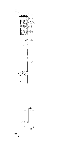
Figure 1 shows a partly sectioned side elevation
of a gauge,
Figure 2 shows a further largely broken away
elevation of the gauge taken on the lines II-II of Figure l;
Figure 3 shows a top view of the gauge;
Figure 4 shows a cross-sectional view of the gauge
on lines IV-IV of Figure 2; and
Figure 5 shows a partial sectional elevation view
of the bottom end of the gauge, on lines V-V of Figure 1.
Ferring to the drawings, the gauge device comprises a square
tube 10 having an open lower end and having a square cap 12
closing the top end; this cap holds a convex sight glass 14. The
length of the tube may be 14 feet. A vent hole (not shown) is
provided near the upper end oE the tube.
Fixed within tube 12 is a yuideway .Eormed by an extruded
aluminum member 16 having opposed sides fixed, as by rivets 17,
to -the inner surfaces of the sides of the tube 10, such that its
front and rear faces 16a are spaced from the front and rear inner
surfaces of the tube. These front and rear faces 16a terminate
short of the top and bottom of the tube 12 and extensions 18 of
the sides of member 16 carry shafts with freely rotatable
rollers 20. Rollers 20 are of suitable diameter for supporting
a readily flexible tape 22 such that the tape is held as a taut
loop between the rollers and is free to move around the rollers

92885
between the front and rear faces 16a of the guide member and
adjacent inner surfaces of the tube 10. The tape 22 has indicia
shown at 22a on i-ts external surface, as with a measuring tape.
Within the member 16 is mounted a longitudinally slidable
float 24, this being hollow and formed of plastics such as
polyvinyl chloride, and being such as to have good buoyancy in
gasoline and also being resistant to attack by gasoline or diesel
fuels. The floa-t 24 is attached to tape 22 by screw means
indicated at 26 in Fig. 4 which pass through a slot in the front
face of the guideway member 16.
The device can be moved from one tank to another, like with
a dip stick, to measure the level of liquid such as gasoline or
diesel oil. When inserted into a tank, the float 24 rests at
the top surface of the liquid so that the indicia 22a on the
tape which is viewed through the sight glass 14 indicates the
level of liquid in the tank. The fact that all moving parts are
surrounded by the tube 10 means that the device can be moved
around from one tank to another with little prospect of any
serious damage occurring. The guideway 16 is a close sliding
fit and maintains proper alignment of the float so that even with
the connection between the float and the tape being eccentic
relative to the float, the float is maintained in alignment and
does not jam in the guideway.

Representative Drawing
A single figure which represents the drawing illustrating the invention.
Administrative Status

2024-08-01:As part of the Next Generation Patents (NGP) transition, the Canadian Patents Database (CPD) now contains a more detailed Event History, which replicates the Event Log of our new back-office solution.

Please note that "Inactive:" events refers to events no longer in use in our new back-office solution.

For a clearer understanding of the status of the application/patent presented on this page, the site Disclaimer , as well as the definitions for Patent , Event History , Maintenance Fee  and Payment History  should be consulted.

Event History

Description Date
Inactive: Expired (old Act Patent) latest possible expiry date 2008-12-10
Inactive: IPC from MCD 2006-03-11
Inactive: Office letter 2001-11-26
Change of Address Requirements Determined Compliant 2001-11-19
Inactive: Adhoc Request Documented 2001-09-28
Inactive: Office letter 1998-04-23
Inactive: Late MF processed 1998-04-06
Letter Sent 1997-12-10
Grant by Issuance 1991-12-10
Small Entity Declaration Determined Compliant 1987-07-29

Abandonment History

There is no abandonment history.

Fee History

Fee Type Anniversary Year Due Date Paid Date
MF (category 1, 6th anniv.) - small 1997-12-10 1998-04-06
Reversal of deemed expiry 1997-12-10 1998-04-06
MF (category 1, 7th anniv.) - small 1998-12-10 1998-12-01
MF (category 1, 8th anniv.) - small 1999-12-10 1999-11-15
MF (category 1, 9th anniv.) - small 2000-12-11 2000-10-30
MF (category 1, 10th anniv.) - small 2001-12-10 2001-11-05
MF (category 1, 11th anniv.) - small 2002-12-10 2002-10-18
MF (category 1, 12th anniv.) - small 2003-12-10 2003-10-27
MF (category 1, 13th anniv.) - small 2004-12-10 2004-11-23
MF (category 1, 14th anniv.) - small 2005-12-12 2005-10-11
MF (category 1, 15th anniv.) - small 2006-12-11 2006-11-29
MF (category 1, 16th anniv.) - small 2007-12-10 2007-10-01
Owners on Record

Note: Records showing the ownership history in alphabetical order.

Current Owners on Record
MICHAEL GORDON WHITE
Past Owners on Record
None
Past Owners that do not appear in the "Owners on Record" listing will appear in other documentation within the application.
Documents

To view selected files, please enter reCAPTCHA code :


To view images, click a link in the Document Description column. To download the documents, select one or more checkboxes in the first column and then click the "Download Selected in PDF format (Zip Archive)" or the "Download Selected as Single PDF" button.

List of published and non-published patent-specific documents on the CPD .

If you have any difficulty accessing content, you can call the Client Service Centre at 1-866-997-1936 or send them an e-mail at CIPO Client Service Centre.


Document
Description 
Date
(yyyy-mm-dd) 
Number of pages   Size of Image (KB) 
Drawings 1993-10-22 1 19
Abstract 1993-10-22 1 32
Claims 1993-10-22 1 32
Descriptions 1993-10-22 3 117
Representative drawing 2002-04-07 1 4
Maintenance Fee Notice 1998-01-06 1 178
Late Payment Acknowledgement 1998-04-14 1 170
Notice: Maintenance Fee Reminder 1998-09-13 1 131
Notice: Maintenance Fee Reminder 1999-09-12 1 129
Notice: Maintenance Fee Reminder 2000-09-11 1 118
Notice: Maintenance Fee Reminder 2001-09-10 1 131
Notice: Maintenance Fee Reminder 2002-09-10 1 117
Notice: Maintenance Fee Reminder 2003-09-10 1 114
Notice: Maintenance Fee Reminder 2004-09-12 1 123
Notice: Maintenance Fee Reminder 2005-09-12 1 118
Notice: Maintenance Fee Reminder 2006-09-11 1 118
Notice: Maintenance Fee Reminder 2007-09-10 1 129
Fees 2003-10-26 1 16
Fees 1998-04-05 1 162
Fees 1998-11-30 1 22
Fees 2001-12-02 1 20
Fees 2002-10-17 2 118
Correspondence 2001-10-24 3 268
Fees 2001-11-04 2 47
Correspondence 1998-04-22 1 7
Correspondence 1998-04-22 1 5
Fees 1999-11-14 1 34
Fees 2000-10-29 1 23
Fees 2004-11-22 1 15
Fees 2005-10-10 3 177
Fees 2006-11-28 2 115
Fees 2007-09-30 3 108
Fees 1994-10-24 1 33
Fees 1996-11-24 1 30
Fees 1995-12-07 1 26
Fees 1993-10-19 1 28