Language selection

Search

Patent 1293014 Summary

Third-party information liability

Some of the information on this Web page has been provided by external sources. The Government of Canada is not responsible for the accuracy, reliability or currency of the information supplied by external sources. Users wishing to rely upon this information should consult directly with the source of the information. Content provided by external sources is not subject to official languages, privacy and accessibility requirements.

Claims and Abstract availability

Any discrepancies in the text and image of the Claims and Abstract are due to differing posting times. Text of the Claims and Abstract are posted:

  • At the time the application is open to public inspection;
  • At the time of issue of the patent (grant).
(12) Patent: (11) CA 1293014
(21) Application Number: 1293014
(54) English Title: FITTING FOR FASTENING THE RAIL MEMBER OF A DRAWER
(54) French Title: FERRURE DE FIXATION D'UN RAIL-GUIDE DE TIROIR
Status: Expired and beyond the Period of Reversal
Bibliographic Data
(51) International Patent Classification (IPC):
  • A47B 88/00 (2017.01)
  • F16B 12/42 (2006.01)
(72) Inventors :
  • ROCK, ERICH (Austria)
  • HOLLENSTEIN, HELMUT (Austria)
(73) Owners :
  • JULIUS BLUM GESELLSCHAFT M.B.H.
(71) Applicants :
(74) Agent: MARKS & CLERK
(74) Associate agent:
(45) Issued: 1991-12-10
(22) Filed Date: 1988-01-07
Availability of licence: N/A
Dedicated to the Public: N/A
(25) Language of filing: English

Patent Cooperation Treaty (PCT): No

(30) Application Priority Data: None

Abstracts

English Abstract


ABSTRACT
Fittings are provided to connect the front plate of
a drawer with a rail member . Each fitting comprises
a dowel casing which can be fitted into the front
plate . Each rail member is at its front end
connected with a hook member which can be engaged
in a dowel casing . A metallic disk is provided
to obtain a more rigid dowel casing. The hook member
comprises a flange which abuts flush with the front
face of the dowel casing and is provided with a
bevelled portion .


Claims

Note: Claims are shown in the official language in which they were submitted.

THE EMBODIMENTS OF THE INVENTION IN WHICH AN EXCLUSIVE PROPERTY
OR PRIVILEGE IS CLAIMED ARE DEFINED AS FOLLOWS:
1. A fitting for fastening an end of a rail member of
a drawer to a front plate or to a rear wall of the drawer, said
fitting comprising: a circumferentially closed dowel casing to be
fitted into the front plate or rear wall of the drawer, said
dowel casing having a hollow interior and a circumferentially
closed circular opening extending through said dowel casing
axially centrally thereof into said interior; a hook member to be
at a respective end of the rail member of the drawer, said hook
member including a head having a hook extending through said
circular opening in said dowel casing to a fastened position to
fasten said hook member to said dowel casing, said hook having a
circumferential dimension extending along a portion only of the
circumference of said hook member, said hook member extending in
the axial direction of said dowel casing and having a cylindrical
shoulder snugly received in said opening when said hook member is
in said fastened position, and said head having a beveled portion
at a position radially opposite said hook to permit insertion of
said hook through said circular opening, said beveled portion
extending from a free end of said hook member to a position
axially beyond said hook; and an abutment surface within said
interior to be abutted by said hook, said abutment surface
extending entirely around the circumference of said circular
opening.
2. A fitting as claimed in claim 1, wherein said
dowel casing is formed of a plastic material, and further
comprising a metal disk positioned within said interior of said
dowel casing and having an opening corresponding to said opening
in said dowel casing.
3. A fitting as claimed in claim 1, wherein said hook
member has a flange abutting flush with said dowel casing, said
flange having a beveled portion opposite said hook.
-6-

4. A fitting as claimed in claim 1, 2 or 3 wherein
said hook member has a threaded portion to be threaded onto the
rail member.
5. A fitting as claimed in claim 1, 2 or 3 wherein
said dowel casing has a cylindrical exterior, and said circular
opening is positioned coaxially of said exterior.
6. A fitting as claimed in claim 2, wherein said
abutment surface comprises a surface of said metal disk.

Description

Note: Descriptions are shown in the official language in which they were submitted.


12~3~
FIEED AND 8ACKGROUND OF THE INVENTION
The invention relates to a fitting for fastening the rail
member of a drawer to a front plate or rear wall of a
drawer, said rail member being provided with a hook member.
In modern furniture construction, drawers are widely known
in which the front plate is adjustably fastened to the
drawer side walls, i.e. to the side walls of the piece
of furniture, by means of clip-in fittings. In some
cases, a rail member is provided at the drawer above each
drawer side wall and extends from the front plate to the
rear wall of the piece of furniture or to a support member
at the rear wall of the piece of furniture.
The same Applicant suggests in a prior application to use
said ra;l member for the adjustment of the front plates.
In this arrangement, the rail member is provided with
a threaded pin which is screwable into a holding member
which is fittable into the front plate.
Furthermore, furniture connectors with dowel-like casings
are generally known which allow a clamping connection
between parts of pieces of furniture~
SUMMARY OF THE INVENTION
It is the object of the invention to provide a connecting
fitting which allows quick engagement of a rail member in
3~

3~14
the front plate or rear wall of a drawer.
According to the invention this is achieved by a dowel
casing which is fittable into the front plate or the like
and into which a hook member is engageable by means of the
hook, said hook member being connected with the rail
member or moulded thereto and projecting through an
opening into the dowel casing.
The dowel casing according to the invention can be
mounted in an easy and quick manner without the necessity
of screws. A particular alignment need not be taken into
consideration. Moreover, the complete fitting is received
in the front plate.
It is advantageously provided that a metallic disk is
inserted into the dowel casing which is made of plastics
material, said disk having an opening through which the
hook member extends with its head.
~y means of the metallic disk, the forces exerted by the
hook can be taken up by a larger area of the dowel casing.
An embodiment of the invention provides that the hook
member is provided with a flange which abuts flush with
the dowel casing in the mounted position and is bevelled
at the side opposite the hook.
Due to this arrangement, the rail member and the hook
member are snuggly held at the dowel casing in the engaged

3C~4
position, the hook member having cylindrical shoulder which is
snuggly received in the opening of the dowel casing, with
engagement and disengagement of the hook member being easy
nevertheless.
In the following an embodiment of the invention will be
described in more detail with reference to the figures of the
drawing in which
Figure 1 shows a diagrammatic view of a drawer
according to the invention,
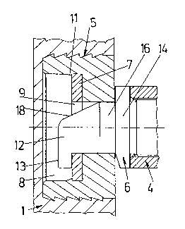
lo Figure 2 shows a vertical sectional view of a fitting
according to the invention, with the rail member being engaged,
Figure 3 shows a vertical sectional view of a fitting
according to the invention, the hook member being shown in an
intermediate position when being engaged and disengaged,
respectively,
Figure 4 shows a side view of a dowel casing according
to the invention, parts thereof in section,
Figure ~ shows a top view of a dowel casing according
to the invention,
Figure 6 shows a side view of the rail member, parts
thereof in section,
Figure 7 shows a side view of the hook member, and
-- 3 --

3~14
Figure 8 shows a front view of the hook member.
In the figures of the drawing, reference numer 1
designates the front plate, reference number 3 the rear
wa(l of the drawer and reference number 2 the side walls
of the drawer.
DESCRIPTION OF THE PREFERRED EMBODIMENT
The fitting according to the invention comprises a dowel
casing 5 which is fittable into the front plate 1 and
a hook member 6 which screwed into the rail member 4.
The hook member 6 is advantageously made of diecasting,
but it can equally be of plastics material.
The dowel casing 5 is ;njection moulded plastics material.
The dowel casing 5 has a hollow space 8 and a central
opening 9. A metallic disk 7 is fitted into the hollow
space 8. The metallic disk 7 is held in an undercut 10
by means of a projection or projections 11.
The hook member 6 has a head 12 with a hook 13.
To permit insertion of the head 12 into the opening 9, the
head 12 has a bevelled portion 18. The rail member 4 is
fastened by pushing the dowel casing 5 into the front
plate 1 in a manner known per se and by then scrr-wing or
inserting the hook member 6 into the rail member 4. Then
the rail member 4 is by means of the hook member 6

3~i~
engageable in the dowel casing 5 through the opening 9
in the manner shown in Fig. 3, so that the hook 13
comes to lie behind the metallic disk 7, as shown in
Fig. 2.
The hook member 6 has a flange 14 which abuts flush with
the dowel casing 5, i.e. at the front side thereof. The
flange 14 is provided with a bevelled portion 15 opposite
the hook 13 to avoid that the flange impedes engaging
and disengaging of the hook member 6.
The avoid wobbling of the rail member 4, the hook member
is provided with a cylindrical shoulder 16 which is
snuggly received in the opening 9 of the dowel casing 5.
The dowel casing 5 has in a manner known per se
circumferential r;bs 17 wh;ch ensure ;mproved anchoring
of the dowel casing 5 in the front plate 1.

Representative Drawing
A single figure which represents the drawing illustrating the invention.
Administrative Status

2024-08-01:As part of the Next Generation Patents (NGP) transition, the Canadian Patents Database (CPD) now contains a more detailed Event History, which replicates the Event Log of our new back-office solution.

Please note that "Inactive:" events refers to events no longer in use in our new back-office solution.

For a clearer understanding of the status of the application/patent presented on this page, the site Disclaimer , as well as the definitions for Patent , Event History , Maintenance Fee  and Payment History  should be consulted.

Event History

Description Date
Inactive: IPC deactivated 2017-09-16
Inactive: IPC expired 2017-01-01
Inactive: IPC assigned 2017-01-01
Inactive: First IPC assigned 2017-01-01
Time Limit for Reversal Expired 2003-12-10
Letter Sent 2002-12-10
Grant by Issuance 1991-12-10

Abandonment History

There is no abandonment history.

Fee History

Fee Type Anniversary Year Due Date Paid Date
MF (category 1, 6th anniv.) - standard 1997-12-10 1997-12-01
MF (category 1, 7th anniv.) - standard 1998-12-10 1998-12-01
MF (category 1, 8th anniv.) - standard 1999-12-10 1999-11-24
MF (category 1, 9th anniv.) - standard 2000-12-11 2000-11-29
MF (category 1, 10th anniv.) - standard 2001-12-10 2001-11-30
Owners on Record

Note: Records showing the ownership history in alphabetical order.

Current Owners on Record
JULIUS BLUM GESELLSCHAFT M.B.H.
Past Owners on Record
ERICH ROCK
HELMUT HOLLENSTEIN
Past Owners that do not appear in the "Owners on Record" listing will appear in other documentation within the application.
Documents

To view selected files, please enter reCAPTCHA code :


To view images, click a link in the Document Description column. To download the documents, select one or more checkboxes in the first column and then click the "Download Selected in PDF format (Zip Archive)" or the "Download Selected as Single PDF" button.

List of published and non-published patent-specific documents on the CPD .

If you have any difficulty accessing content, you can call the Client Service Centre at 1-866-997-1936 or send them an e-mail at CIPO Client Service Centre.


Document
Description 
Date
(yyyy-mm-dd) 
Number of pages   Size of Image (KB) 
Cover Page 1993-11-03 1 11
Claims 1993-11-03 2 54
Abstract 1993-11-03 1 10
Drawings 1993-11-03 2 43
Descriptions 1993-11-03 5 98
Representative drawing 2000-08-01 1 10
Maintenance Fee Notice 2003-01-07 1 173
Fees 1995-11-29 1 62
Fees 1996-11-20 1 66
Fees 1994-11-24 1 55
Fees 1993-11-26 1 50