Note: Descriptions are shown in the official language in which they were submitted.
3~
-- 1 --
TITLE OF THE INVENTION
SUSPENSION PEG
5 BACKGROUND OF THE INVENTION
1. Field of the Invention
The present invention relates to a suspension
peg comprising a wire bent on i~self and forming a
securing eye, one of the ends of the wire, intended to be
introduced into an anchorage hole being adapted so as to
cooperate, under the action of an outward tractive force
exerted on the eye, with anchorage means and anchoring
the peg in the wall of the hole.
Suspension pegs are used mainly for securing
false ceilings, their securing eye providing the
connection with a bar, a wire, a rail or any other
similar suspension means.
Most of the suspension pegs normally used are
expensive to manufacture, because of the pressing,
boring, turning or heat treatment operations which they
must undergo depending on the case.
2. Description of the prior art
From the American patent 2 878 668* a peg is
known of the above mentioned type in which the anchorage
end of the wire, the other not playing any role, is
curved in the form of a hook so as to drive a key against
an ~anchorage wedge, so as thus to be able to exert a
wedge effect and provide anchorage of the key and of the
;~ wedge and so of the peg in the hole.
However, and because one of the ends o the
wire plays no rolè in the anchorage, the resistant
section of this prior art peg is too weak.
The invention of the present application aims
at overcoming this drawback.
: : :
I * More particularly U.S. 2,878,668 March 1959, Starling et al
33''36
SUMMARY OF THE INVENTION
For this, the present invention relates to a
peg of the above defined type, characteri~ed by the fact
that both ends of the wire are intended to be introduced
into the anchorage hole and they are adapted so as to
cooperate with each other and with the anchorage means,
under the action of said tractive force, for anchoring
the peg.
With the invention, the resistant section of
the peg is good since both ends of the wire participate
therein.
The invention in one aspect provides a
suspension peg to be anchored within a hole defined
within a support and from which objects may be
suspended, comprising a wire bent upon itself so as to
form at one end of the peg a substantially annular
securing eye portion, mating wire ends at the other end
thereof. An intermediate portion of the suspension peg
is defined between the annular securing eye portion and
the mating wire ends. Expansible collar means has a
predetermined inner diametrical extent and is disposed
about the intermediate portion for engagement with
interior wall portions of a support hole when the
expansible collar means is radially expanded so as to
anchor the suspension peg within the hole. The mating
wire ends including the expansion means has an outer
diametrical extent which is greater than the inner
diametrical extent of the expansible collar means for
operatively engaging the expansible collar means under
the influence of a tractive force exerted upon the
sécuring eye portion in a direction extending outwardly
from the hole and for radially expanding the collar
means into anchoring engagement with interior wall
portions of the hole.
,.,i.~ ~,
- 2a -
Another aspect of the invention provides a
suspension peg to be anchored within a hole defined
within a support and from which objects may be
suspendingly supported, comrpising a wire bent upon
itself so as to form at one end of the peg a
substantially annular securing eye portion mating wire
ends at the other end thereof. Wedge-shaped recess
means is defined within the mating wire ends and has a
~ertex portion disposed toward the other end of the
suspension peg and a base portion disposed toward the
one end of the suspension peg. Wedge-shaped expansion
means is correspondingly disposed within the wedge-
shaped recess means for causing radial expansion of the
mating wire ends into anchorage engagement with interior
wall portions of a hole defined within the support as
the mating wire ends and the wedge-shaped recess means
thereof are moved relative to the wedge-shaped expansion
means under the influence of a tractive force exerted
upon the securing eye portion in a direction extending
outwardly from the hole.
In a preferred embodiment the mating ends of
the bent wire form a truncated expansion cone adapted
for cooperating with an expandable anchorage socket.
In another embodiment the mating ends of the
wire each has an expansion ramp within a recess
containing an expansion wedge so that, during tractive
force exerted on the eye, the mating ends are anchored
in the wall of the hole.
The peg of the invention may include a
semicylindrical wire with a flat face, bent on itself,
along its flat face.
" The peg of the invention may also include a
wire obtained by die stamping a metal strip, this being
very economical on a manufacture standpoint.
In this case, the ends of the wire bent on
itself may form a body with two cylindrical
,~ shells including a closure disk formed by a
,~:
t~ ' ? `~
bent extension of one of the shells and bearing on the other
one, for making the body relatively indeformable.
BRIEF DESCRIPTION OF THE DRAWINGS
The invention will be better understood frGm the follo-
wing description of several embodiments of the peg of the
invention with reference to the accompanying drawings in
which :
Figure 1 is a perspective view of the first embodiment
of the peg of the invention ;
Figure 2 is a front view of the end portion of the
second embodiment of the peg of the invention ,
Figure 3 is a side view of the peg portion of Figure 2 ,
Figure 4 is a cross sectional view of the peg portion
ZQ of Figure 3 through line IV-IV ;
Figure 5 is a perspective view of the end portion of
the third embodiment of the peg of the invention ;
Figure 6 is a perspective view of one of the ends of
the starting metal strip in a fourth embodiment of the peg
of the invention, after cutting out ;
Figure 7 is a perspective view of the end of the metal
strip of Figure 6, after bending ;
. ~ ~
Figure 8 is a perspective view of the end of the metal
st`rip of Figure 7, after die stamping ;
Figure 9 is a side view of the peg of Figures 6 to 8
: Figure 10 is a perspective view of one of the ends of
the starting metal strip in a variant o~ the peg of Figures 6
., ~ jr ~ to 9 ;
,
396
Figure 11 is a sectional view of the variant of the
peg formed from the metal strip of Figure 10 ; and
Figure 12 is an end view of the peg of Figure 11.
DESCRIPTION OF THE PREFERRED EMBODIMENTS
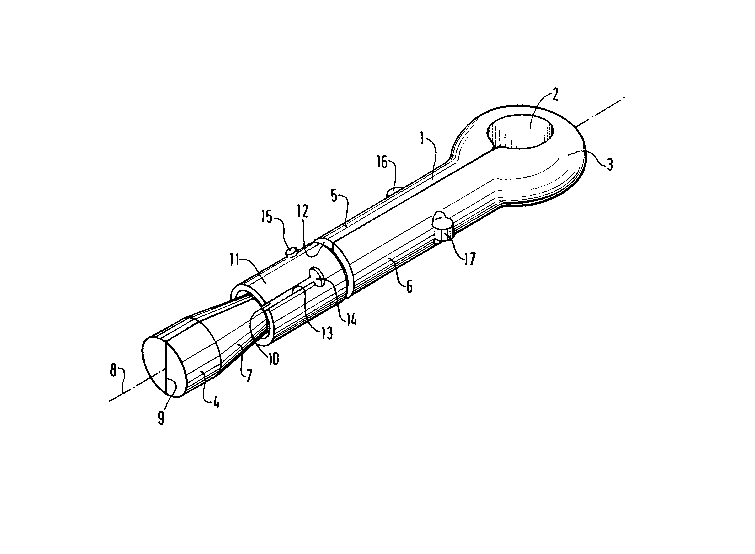
The peg shown in Figure 1, which is a suspension peg
for false ceilings, has been formed from a semicylindrical
solid wire 1 with a flat face 2, that is to say having a
semicircular cross section. It should however be stated
; that the wire of the peg of the invention could have a
semi-elliptic or rectangular section.
Wire 1 has been bent on itself, along its flat face 2
so as to form a securing eye 3 at one end of the two legs 5,
6 thus formed as well and, at the other end, a cylinder
portion 4 of circular section formed by the juxtaposition,
through their diameters, of two semicylindrical sections of
the starting wire, and with an axis X extending in the
plane of the joint 9 of the two legs 5, 6, these two sec-
tions acting one on the other so as to form a relatively
indeformable body during tensioning of the peg, which will be
described further on. To accentuate this effect, scores may
be formed on the faces which cooperate together.
The two side by side legs 5, 6 have been shaped,
before or after bending, over a portion adjacent the
cylindrical end portion 4 so as to form a truncated cone
;30 shaped portion 7 with axis 8. Beyond this truncated cone
portion 7, on the other side with respect to the cylin-
drical end portion 4, the two legs 5, 6 have been shaped
s`o as to form another cylindrical portion 10 of reduced
diameter and a annular shoulder 12.
:~ :
:
~3~3~3~i
On the reduced cylindrical portion 10 is
mounted a cylindrical expandable anchorage socket 11,
with axis 8, having an internal diameter slightly greater
than the diameter of the reduced portion 10 and having an
external diameter substantially equal to the diameter of
the circular section of the two side by side legs 5, 6.
At rest, socket 11 extends substantially between the
truncated cone portion 7 and the annular shoulder 12. It
participates in holding the legs in their side by side
position. Socket 11 has been obtained from a rectangular
plate, rolled on itself, with its two opposite edges
joined side by side, not visible in -the Figure. An
-- additional expansion slit 13 has been formed therein,
parallel to axis 8, with an end opening 14 for
facilitating the expansion. Socket 11 comprises
immobilization studs 15.
Legs 5, 6 have positioning studs 16, 17, here
diametrically opposite in the same plane perpendicular to
axis 8.
A peg has been described formed from a wire
with a flat face. This is not a limitative characteristic
of the invention, although it is advantageous. In fact,
instead of bending back two flat faces one on the other,
two complementary faces, for example one convex and the
other concave, could be bent back, but at the price of a
pointless complication in shaping.
The peg could also be formed of a so called
half elliptic wire which, by bending back, leads to an
elliptic section and not a circular one, or else from a
wire with square or rectangular section, giving a
rectangular section.
,~
?33~
-- 6
The operation for anchoring the peg of Figure l
will now be described.
Having previously bored a hole in ~he receiving
material, of a diameter slightly greater than the
exter~al diameter of the socket 11 but slightly less than
the overall distance between the two positioning studs
16, 17, the peg is fitted into the hole by its
cylindrical end portion 4, using a tool such as a hammer
for example, until the positioning studs abut against the
edge of the hole. The positioning studs define then the
penetration depth of socket 11. Then, using the same tool
but this time as a lever, a tractive force is exerted
externally of the hole on the peg by means of its eye 3.
With the soc~et immobilized in- translation at the
beginning of the tractive force by its studs 15, the
expansion cone 7 penetrates into the socket which will
open until it is anchored in the wall of the receiving
hole. The peg is then itself anchored in the hole.
A single tool is sufficient for fitting the peg
and anchoring it.
Figure 5 shows a variant of the peg of Figure
1, in which the circular 10 and truncated cone 7 surfaces
of Figure 1 are replaced respectively by flat surfaces
1~, l9, 20 and 21, 22, 23 so as to give the peg square
25 sections, surfaces 21, 22, 23, the closest to the ends,
forming a frustum of a pyramid. The side of the square
18, l9 and 20 is such that it forms shoulder 12 and
allows the assembly of socket 11, as in the embodiment
shown in Fiugre 1.
It will be noted that, instead of an expandable
socket, it is possible in one embodiment of the peg of
the invention, closely related to those which have just
been described, to use two lateral wedges shaped so as to
cooperate with two opposite expansion ramps formed on the
two ends of the bent wire, respecti~ely.
The embodiment of the peg shown in Figures 2 to
4 is identical with that shown in Fi~ure l, except or
396
its end and its anchorage means.
The two ends of the starting wire, before
bending the legs 25, 2~ one on the other, are shaped so
as to provide respectively, from the two flat end
starting surfaces 29, 30, two ramps 27, 28 slanted in
opposite directions and two adjacent lands 31, 32 forming
two shoulders 33, 34 with the flat starting surfaces 29,
30. After bending, the end portions of the legs 25, 26 of
the peg are bent back on a wedge 35. Having a general
rectangular shape on one side, wedge 35 has on the other
side, perpendicular to the first side, a section
corresponding to the recess of the legs, with a
rectangular portion at the rear, against the shoulder 33,
34, of a width equal to the distance separating the two
lands 31, 32 and a triangular portion at the front,
between ramps 27, 28 with, as plane of symmetry, the
joint plane 39 of the legs 25, 26 of the peg. Wedge 35
has two immobilizing studs 36, 37 which project from the
legs of the peg throu~h openings formed by the ramps and
the adjacent lands.
It will be noted that in an embodiment very
similar to that which has just been described the wedge
could be of a general conical shape and the ramps and
lands of the legs replaced ~y corresponding conical
surfaces.
For anchoring the peg shown in Figures 2-4, the
procedure is the same as for that of Figure 1, but in
~his case, it is the ends of legs 25, 26 which, in their
translational movement and by engagement with wedge 35
secured against translation by studs 36, 37, move away
from each other so as to anchor themselves in the wall of
the anchorage hole.
.
3 2'~ 3~ki
-- 8 --
The peg shown in Figs. 6 to 9 has been formed from a
metal strip 41, that is to say a long and thin strip of
metal sheeting with two axes of symmetry, one 42
longitudinal and the other perpendicular to the ~irst
one.
Starting then with the metal strip considered,
each of its longitudinal end portions is shaped by
cutting out, laterally on both sides of axis 42, a small
trapezoidal portion so as to form, from the end towards
the middle portion of the strip, a rectangular portion 43
o the same width as the initial metal strip, a
trapezoidal portion 44, adjacent the portion 43 by its
large base of the same width, a rectangular portion 45,
narrower and longer than portion 43, adjacent the
trapezoidal portion 44 by its small base and, connected
to the middle portion by two shoulders 46, slanted ~ith
respect to axis 42 (Fig. 6). About the connection zone
connecting shoulders 46 to portion 45 on one side of the
metal strip, and the connection zone connecting shoulder
~20 46 to the middle~portion, on the other side of the metal;;
strip, each end portion 43, 44, 45 is bent bacX~througn
; 90 in one direction and the adjacent middle portion 41
of the metal strip through 9O in the other direct~ion, ~;
; ~ and the end portion is bent about the two bases of
t-aoezoidal portion 44 respectlvelv in two opposite~
directionc for bringing the rec~angular end por~ion 43
substant~ally into;the same plane as the m~`ddle portion
~l of the metal s~rip thus cut out and shaped (Flg. 7 ).
: ~
; ~ ; ` ,
: ~
: ~ .
33~
g
In a die o~ approDriate shape, the metal strip
is deformed, the rectangular end portions 43 and the
middle portion 41 according to a first radius of
curvature and the narrowed rectangular portions 45 in
accordance with a second radius of curvature smaller than
the first one, the trapezoidal portions 44 being deformed
so as to join up with the cylindrical adjacent portions
(Fig. 8).
The me~al strip thus cut out, bent and
deformed, in the shape of a wire, is bent back on itself
along axis 42 and substan~ially about the transverse axis
so as to form a securing eye 53, at one end of two legs
55, 56 and, at the other end, a cylinder portion 54
formed by the two portions 43 then in the form of shells,
a first truncated cone shaped expansion portion 57,
adjacent portion 54 and formed by the two portions 44
and, beyond, on the other side with respect to ~he
cylindrical end portion 54, another cylindrical portion
60 formed by the two portions 45, of restricted diameter,
and an annular shoulder 62, thP portions 43, 44, 45 and
41, these latter between eye 53 and shoulder 62, being
joined together in pairs by their two respective edges
along the same joint plane (Fig.9 ).
In another embodiment of the peg of the
invention (Figs. lO, 11,12) and the same reference figures
being used for designating the same means, starting with
a me2al strip substantiall~ longer than the preceding
one, beyond one of the t~o rectangular end portions 43
a projecting tongue 47 is formed, still bv cutting out,
.~hich extends the rectangular end portion along the ax s
42 and having a~ the end a closure dis~ 48 intended to be
bent back substantially through 90 so as to be engaged,
after bending of the metal st-ip (of the wi~e), between
the t~o shells 43', 43" substan~iallv in their end plane,
35 bur in abutment a~ains2 sAell 43" opposite that 43'
~33~6
-- 10 --
carrying this closure disk 48, and so thus to oppose
closure or flattening o~ ~he two shells. For this, two
slits 49 are formed in the rectangular portion 43'
concerned, p~rallel to axis 42 and in the extension of
the side walls of tongue 47, so that disk 48, after
bending back of the metal strip, comes into abutment on
the inside against the other shell 43" (Fig.ll~.
On the narrowed cylindrical portion 60 is
mounted a cylindrical expandable anchorage soc~et 61,
with axis 42, of an internal diameter slightly greater
than the diameter of the narrowed portion 60 and with an
external diameter substantially equal to the diameter of
the circular section of the two legs 55, 56 applied side
by side. At rest, socket 61 extends substantially between
the truncated cone shaped portion 57 and the annular
shoulder 62. It participates in holding the legs in their
side by side position. Socket 61 was obtained from a
rectangular plate, rolled on itself, with its two
opposite edges applied together. Socket 61 includes
immobilizing spurs (not shown).
Legs S5, 56 include a positioniny colIar 66, in
; the same plane perpendicular to axis 42, formed during
shaping of the metal strip.
Still during shaping of the metal strip, in the
central part 41, intended to become the eye 53, a rib 50
is formed, here by displacement of material, which, as
internal projection, plays a stiffenin~ role after
bending of the metal strip (Figs.9, ll and 12).
The procedure for anchorin~ this last peg, simi-
~30 ~ lar to the previous one, will now be ~escribed.
Having beforehand bored a hole in the receivingmaterial, of a diameter slightly greater than the
external diameter of socket 61 but slightly less than the
diameter of the positioning collar 66, the peg is fitted
i~nto the hole by its cylindrical end portion 54, using
the same tool, until the positioning
collar abuts against the edge of the hole. The
~,
33''3;
-- 11 --
positioning collar then determines the depth of penetra-
tion of the socket 61. Then, using the tool, thus serving
this time as lever, a tractive force is exerted on the peg,
through its eye 53, directed outwardly of the hole. With
the socket immobilized in translation from the beginning
of the tractative force by its immobilization spurs, the
expansion cone 57, the end of the peg forming a relatively
indeformable body because of the closure disk, penetrates
into the socket which will open until it is anchored in
the wall of the receiving hole. The peg is then itself
anchored in the hole.
It will be noted that, in the absence of the closure
disk, the cooperation of the edges of the end shells would
prevent these shells from being crushed too readily.
It will also be noted that, for forming the peg, the
step illustrated in Figure 7 could be avoided by passing
directly from the step shown in Figure 6 to that shown in
Figure 3.