Note: Descriptions are shown in the official language in which they were submitted.
MI-3555.cl
MOUNTI~G FOR 8IG~ RESOLUTION
FI~LD OF INVBNTION
T~e pre~ent invention relates to aparati and methods
for mounting high resolution pro~ection len~e3 and, ~ore
parti~ularly, to ~uch aparati and methods wherein the len~ i
mounted to the lens cell following the machini~g of ~he cell.
~' .
BACRGROUND O~ TID~ N~ION
In order to get optimum performance from high
re~olution lithographi~ len~ assemble~ ~t i~ imperative that
; all len~e~ ln a given as~embly be centered, within a few
micron~, to a common optlcal axis. Further, the~e len~
: mounts are expected to maintain an extremely high level of
performance under a multitude of environmental condition~
during use, storage and shippingO
. ~
S33~
Lenses are commonly affixed within lens cells with
mechanical devices. Differences in the coefficient of
thermal expansion between the lens and the lens cell can lead
to decentration and intolerable stresses in the lens during
ambient temperature changes.
~ ,.
~ ~ One approach to the solution of the foregoing
;~ problems is given by Canadian Patent Application Serial
No. 527,707, filed January 20, 1987 which is assigned to the same
assignee as the present invention. This approach calls for
the lens to be mounted to a lens cell through flexure means.
These flexure means return the lens to a predetermined
spatial relation to the lens cell following temperature
excursions away from, then back to, the datum temperature.
Following the lens being mounted to the lens cell the outer
diameter and upper and lower surfaces of the lens cells are
precision machined with respect to the optical axis oE the
lens.
While this approach offered significant advantages
over the prior art in does have several drawbacks. There is
a chance of damaging the lens mounted in the lens cell during
.
the machining of the lens cell. Also, if an error were made
in machining the lens cell it is relatively difficult to
remove the lens for installation in another lens cell. This
last feature is desirable in that the lenses are quite
expensive.
The present invention eliminates or ameliorates the
foregoing disadvantages of the prior art by providing a lens
mount unaffected by large temperature excursions, which can
be easily and safely machined without endangering the lens
and which can be easily disassembled. In addition, the lens
mount provided is very stable and has a high resonant
` frequency.
. :
~`:
.:`
~r
' ~ :
3~
- 3 - MI-3555.Cl
8RI13F D~5SCRIPT:CON_OF T~IB INVI~NTIOY
In order to achieve the de~ired result~ he pre~ent
invention provides an apparatus and method for the mounting
of lense~ to lens cells.
Briefly, the lens cell i~ machined with a ~pherical
seat for a lens concentric ~ith the axi~ of rotation. The
outer diameter of the lens cell i~ concentric with the axi~
of rotation and the top and bottom surfaces of the len~ cell
are machined perpendicular to the axis of rotation. Three
~, 10 flexure a~sembles are then affixed to the inner diameter of
~ the leos calls.
: ,
The lens cell i~ then placed on an air-bearing table
and centered on it~ axis of rotation by indicating the
reference outer surace ~y using an electronic/air gageO The
len~ i~ then placed on its seat in the cell. An
electronic/air gage i8 used to indicate the top surface of
~he lens and the air-bearing table i~ rotated. ~he len~ ~
then moved on its seat, relative to the len~ cell, ~o as to
minimize the wobble of the top surface of the len~. At thi~
~tage, the axi~ of the len~ i~ concentric with the sxis of
the air-bearing table and the axis of the outer diameter of
the len~ cell. ~he lens i then bonded to the three
:~ flexure~.
.
"
~!
-
3~
- 4 - ~I-3555.Cl
A len~ a~embly can be made by ~tac~ing tvgether a
plurality of lens cell~ fabricated in the manner ~u~t
described. The~e cells are stacked and centered on the axi~
of an air-bearing tabls by bringing all of their out~ide
diameter~ into concentricity. The pluriality of len~ cell~,
80 alignedJ are then bonded together to obtain the final len~
a~sembly.
There has thus been outlined rather broadly the more
important features of the invention in order that the
detailed description thereof that follow~ may be better
under~tood, and in order that the present contribution to the
art may be better appreciated. There are, of cour~e,
addit$onal features of the invention that will be described
hereinafter and which will for~ the subject of the claims
appended hereto. Tho~e skilled in the art ~ill appreciate
that the conception on which the disclosure is ba~ed may
readily be utilized as a ba~is for de~igning other structure~
for carrying out the ~everal purpo~es of the inveniton. It
Ls important, therefore, that the claim3 be regarded as
in~luding ~uch equivalent struotures a~ do not depart ro~
: the ~pirit and scope of the lnvention.
Specific embodiments of the invention have been
cho~en for purpo~es of illustration and description, and are
~hown in the accompanying drawings, forming a part of the
specification.
3~
5 _ MI-3555 Cl
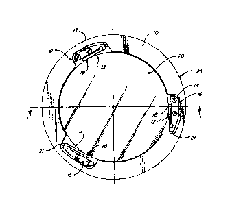
BRI~ D13SCRIPTION OF TH~ DRA~INGS
Fig. 1 is a ~ide ~ectional vie~ of a len~ cell in
accordance with the prese~t invention showing the lens
attached;
Fig. 2 is a plan view of the :Lens cell of Fig. l;
and
Fig. 3 show~ a variation of the flexure~ of Fig. 2.
D~TA~D D~SCRIPTION OF A PREF~RRED EMBODIMENT
Fig. 1 ~how3 a ~ide ~ectional view of a lens cell 10
having a lens 20 conatrained therein.
The lens cell 10, has a top face 28, a botto~ face
24, an out~ide diameter 26 and a ~pherical ~urface 22. The
len~ 20 has an upper surface 23 and a bottom surface ~1.
When the lens 20 and lens cell 10 are properly
as~embled toqether, in a manner described hereinbelow, their
con~titue~t element~ have the following interrelat$on~hips:
the outside diameter 26 of the len~ cell i8 concentric about
an a~i~ of rota'cion 19; top face 28 and bottom face 24 are
: perpendicular to the ax~s of ro'cation 19~ axis of rotation 19
i~ the ~y~metric axl~ of rotation of ~pherical ~eat 225 the
~pherical surface 21 of len~ 23 matches the ~pherical ~eat 22
of the lens cell 10 ~Thi~ rel~tion~hip en~ures tha~ the
optic~l a~i~ of ~pherical sur~ace 22 Ls the axi~ o~ rotation
l9o ) ~ and the optical ~xls of the upper ~urface 23 o~ len3 20
; 25 1~ coincident with a~is of ro~tion 19.
.
.
3~2a ~
- 6 - MI-3555.Cl
The a~ove d~scribed interrelationships can be
: e~tabli3hed in the manner described hereinbelow.
The lens cell i~ mounted on a l~the, preferably
supported by air bearings, and machined, preferably u~ing
diamond point tooling. The machining apparatus does not
constitute a part of the preseng invention and i~,
con~equently~ not shown. ~he out~ide diameter 26 of the len~
cell 10 i~ machined to be concentric with the axis of
rotation of the lathe, thus establishing the axis of rotation
19~ Top face 28 and the bottom f~ce 24 of the 1ens cell 10
are machined to be perpendicular to the axis. The ~pherical
seat 22 i8 machined to match the curvature of the bottom
surface 21 of lens 20. In addition, the spherical seat 22 i8
machined to have a symmetrical axi~ of rotation coincident
~ 15 ~ith the axis of rotation 19.
: Following its machining the lens cell i8 placed on a
precisioD rotating ~urface~ for example, an air~-bearing
table. It is then centered on lt~ ~Xi8 of rotation 19 by
indicating the outer diameter 26 u4ing, for example~ an
electronic/air gage. ~he len~ 20 i~ ~hen placet on the
spherical seat 22 in the l~ns cell 10.
By preci~ely machining spherical ~eat 22 and
ma~ching spherical 3eat 22 to 3pherical ~urface 21 of len~ 20
: the optical axis o~ spherical surface 21 i~ on the axi3 o
rotation l9. The optical axls of surface 23 o~ lens 2Q,
; however, may not be on the axi~ of rotatlon 19 where, for
example, ~urface 23 l~ aspherlc.
3~
- 7 - ~I-3555
Accordingly, a gage, for example, an electronic/air
gage, ~ placed on surface 23 and th~ lens cell 10 i~ cau~ed
to rotate, ~hich cau~e3 the lens 20 to likewi~e rotate. The
lens 20 is then rotated relative to the len~ cell 10 ~o as to
minimize the run out detected by the gage, not ~hown~ A
lubricant, such a~ Teflon or ~oly, can be provided on
~pherical seat 22 to facilitate this movement process.
At thi~ point the axis of rotation 19 i~ shared by
the optical axes of ~urfaces 21 and 23 of the lens, the
rotational axi~ of ~ymmetry of spherical ~eat 22 and the axi~
of rotatlon of ou~er diameter 26 of the lens cell 10. In
addition, the top ~ace 28 and bottom face 24 of l~ns cell 10
are perpendicular to the axis of rotation 19.
Fig. 2 i~ a plan view of the len~ cell 10 and lens
10 of Fig. 2. In addition, Fig. 2 ~hows the three flexure
as~emblie~ 15-17 used to bond the lens 20 to the cell lOo
The flexure assemblie~ 15-17 are attached to the len~ ~ell
~ through the use of, for example, screws 1~. After their
: attachment by ~crew~ 14 the flexure a~emblie~ 15-17 c~n be
rigidly fixed to the lens cell 10 by dabs of epoxy 21. The
ac~ual bonding for the len~ 20 to the flexure as~emblie~ 15-
17 i8 accompli~hed by bonding the ou~er diameter of the len3
20 to the flexure arms 11-13 through an epoxy bondl~ne 18.
The epoxy bondline 18 is, for ex~mple, an ultra violet curing
: 25 epoxy and ~ appllea in any convenient ~anner.
Flg. 3 show~ a variation of the three flexure
assemblies 15-17. In this varia~ion bo~h ends of each
~ flexure arm, ~.g. 9 flexure arm 11 of flexure as~embly 15 are; connected to the main body of the flexure a~semblies. In
this case, the len~ 13 bonded to the flexure arm~ at the
center protru~ion~ lla, flhown ln Fig, 3.
3~
- 8 ~ 3555.C1
~ The purpo~e and function of t:he fle~ure a~emblie~
: 15-17 i~ similar to that of the flexure~ described in ~S.
; Patent Application No. 5Attorney Docket ~o. ~I-3360).
Briefly, the flexure arm3 11-13 ~ttach the lens 20 to the
len3 cell 10 through tbe flexure asse~blies 15-17,
re~pectively. As the am~ient temperature cycles up or down
from a datum temperature the relative diameter~ of the lens
20 and lens cell change due to diff~ring thermal coefficients
of expan~ion. The flexure assemblie~ 15-17, through flexure~
arms 11-13, re~pectively, and bondline~ 18 hold the lens 20.
~9 the relative diameters of the len~ 20 and lens cell 10
change the flexure arms 11-13 flex or move rel~tive to the
bodies of the flexure a~emblies 15-17, hence relative to the
: lens cell 10. At no time do ~he flexure arm~ 13,-lens 20
or bondline 8 reach ~he allowable stre~ limit~ of the
respective material~.
.~
When the a~bient temperature return~ to the datum
temperature the len~ ~0 and lens cell 10 return to their
original, as assembled, relationship.
The flexure a3se~ble~ 15-17 thus allow compensation
for ambien~ temperature changes an~ serve to con train the
len3 20 ~lthin the len~ cell 10 wlth high stabillty and high
re~onance. That i8, at the datum temperature the lens 20 i~
`~ held ln a subYtantially fixed spati~l relation~hip to the
lens cell 10.
Since th~ flexure a~emble~ 15-17 are attached to
the le~s cell 10 through ~cew~ 14 and dabs of epoxy 21, th~y
can be easlly removed at ~ny time. Such r~oval may be
'~
necessary if the lens cell 10 were improperly machined and it
is desired to salvage the lens 20. In this case the lens 20,
with attached flexure assembles 15-17, would be removed from
the lens cell 10. A suitable solvent would be used to
dissolve the bondline 18 between each of the flexure arms 11-
13 and the lens 20. The lens 20, undamaged, is now ready for
assembly in another lens cell in the manner hereinabove
described.
A plurality of lens cells 10 machined in the manner
described hereinabove, having substantially equal outside
diameters 26 can be assembled in a co-axial assembly. This
is done by stac]cing such a plurality of lens cells 10 in such
; a way that their outside diameters 26 share a common,
imaginary, cylindrical surface. In this way t.he opti.cal axes
of all lenses within such a stack of l.ens cells are co-axial.
By ensuring that the top face 28 and the bottom face 24 of
~ the lens cell 10 are perpendicular to the axis of rotation 19
: wedge conditions between lenses 20 in adjacent lens cells 10
can be eliminated or ameliorated. Following stacking and
aligning the plurality of lens cells are epoxied together to
form a unitary assembly, not shown. The stacking, aligning
and epoxying of the plurality of lens cells can be
accomplished in a manner similar to that described in
aforesaid Canadian Patent Application No. 527,707.
There has thus been described a lens mount which is
unaffected by large temperature excursions, which can be
easily machined without endangering its corresponding optical
element or lens and which can be easily disassembled.
Further, this lens mount is very stable and has a high
resonance frequency and is stiff in the axial direction.
,