Note: Descriptions are shown in the official language in which they were submitted.
~939~1~
METE~OD ~ND APP~RATUS FOR SPRAY COATI~G OF REF~ACTORY
MATERIAL ~O REFRACTORY CONSTRIJCTION
BAcKGRou~) OF T~lE I~VENTION
Field of the Invention
The present invention relates generally to a
method and apparatus for safely performing spray coating
of a refractory material onto a re:Eractory construction.
More specifically, the invention relates to a safely and
10` effectively repairing refractory constructions, such as
coke ovensi kilns, furnaces and so forth. Further
particularly, the invention relates to a spray coating
technic avoiding danger in spray coating of the
refractory material containing fine particles of powder
state combusible metal.
Description of the Background Art
Coke ovens, kilns, furnaces employ refractory
linings for constituting refractory constructions so as
to allow substantially high temperature operations.
Such refractory linings thus subject substantially high
temperature for a long period of time to cause hot tear,
spalling, formation of defect, crack and so forth. As
is well known, the coke oven and some kind of furnaces,
such as brust furnace, have to be in operation
continuously throughout their lives. Accordingly,
repair of such hot tears, spalling, defects, cracks and
so forth is to be preformed without stopping the
operation.
Conventionally, repairing operations for the
refractory linings have been taken place by way of spray
coating. Such spray coating process has been disclosed
in the Japanese Patent Second (examined) Publication
(Tokko) Showa 49-46364. In the disclosed process, a
refractory material is selected to have same composition
to that of the refractory lining to be repaired. The
refractory material is mixed with a certain amount of
fine particle of powder state combusible metal. In the
spray coating operation, heat generated by combustion of
the metal powder utilized for melting or half~melting
the refractory material and for adhering the refractory
material onto the refractory lining. At the same time,
the metal oxide formed as a resultant of combustion also
serves as refractory material.
In such a conventional spray coating process,
it is considered that a caloric value required for
o performing spray coating of refractory material for
repairing refractory linings is in a range of 5000
kcal/kg to 8000 kcal/kg, as recited in '~Spray Coating
Repair of Coke Oven'' (Seitetsu Kenkyu Vol. No. 305),
published on 1981, and ''Development pf Spray Coating
~pparatus and Study of Spray Coating Condition'' ~''Iron
and Steel'' No. ~, Vol. No. 169), 1983. Whereas the
caloric value may be generated according to the process
recited in the afore-mentioned publications is in a
range of 2000 kcal/kg to 3000 kcal/kg. Though the
proposed process includes inclusion of 20 Wt% to 30 Wt%
of metal particle in the refractory material in a form a
mixture, which metal particle will serves as
combustioning medium. However, the caloric value to be
generated by the proposed process is too small to melt
or half-melt the refractory materals to be injected onto
the surface of the refractory lining. This degrades
adherence ability of the refractory material onto the
reflactory lining. Furthermore, due to lack of caloric
value, formation of satisfactorily high density
refractory layer and firm adherence of the formed
refractory layer on the reflactory lining have been
diffiCult. It would be possible to increase caloric
value of the heat to be generated during combu~tion by
increasing the concentration of the metal powder.
However, increasing of the amount of the metal powder
concentration apparently cause increasing of the cost
lZ9341~
required for repairing.
In addition, in the prior proposed process,
the metal powder is limited the particle size in
diameter to be smaller than 50 ~m. The metal powder of
the aforementioned limited particle size is carried by
oxygen flow. This makes it difficult to practical
process due to high combusibility of such fine particle
of metal, which causes danger in carrying and back-fire
in spray coating process.
Furthermore, since the calory for spray
coating is generated only by combustion of the metal
particle in the aforementioned prior art, the refractory
lining to be repaired cannot be heated in advance of
starting spray coating. As a result. the refractory
lining to be treated is rapidly heated at a spot. The
heating spot of the refractory lining is rapidly cooled
when the spray coating operation is terminated. This
tends to cause spalling in the refractory construction
to be repaired.
SUMMARY OF TEIE INVENTION
Therefore, it is an object of the present
invention to provide a method and an apparatus for spray
coating of refractory material, which can perform
operation safery and effectively.
Abother object of the invention is to provide
a method and an appratus for spray coating of refractory
material onto a surface of a refractory construction.
which allows relatively great particle size metal to be
used.
A further object o the invention is to provide
;~ a method and an appratus for spray coating, which can
form a frame directed toward the surface to be treated,
independently of the spray coating operation for
allowing moderate warming-up and cooling-off of the
surface of the refractory construction in order to
prevent the portion to be treated from causing spalling.
341~
In order to accomplish the aforementioned and
other objects, spray coating, according to the present
invention, is performed utilizing a mixture of
refractory material and a relatively large average
particle size of powder state combusible metal. The
size of the particle of the metal in the mixture is
selected so that the particle size is large enough to be
treated saely and is small enough to be transported by
means of a gas flow and to be effectively combustioned
without requiring substantial increase of the cost. As
a carrier gas for carrying the mixture, a non-combusible
gas or Euel gas and other non-oxidation gas can be used.
A fuel gas and an oxygen containing combustion-assisting
gas, such as oxygen gas, air and so forth, are
discharged toward the section to be treated on the
surface for directing a combustioning frame. The
refractor material with the carrier gas is discharged
into the frame established by the fuel gas and the
combustion-assisting gas.
In view of the safety in operation, the size
of the metal powder to be used in the spray coating
according to the invention, is limited to be greater
than 50 ~m in diameter. By enlarging the particle size
of the metal, combusibility of the metal powder is
lowered. Combustion of such large particle size metal
can be assisted by discharging the combustion-assisting
gas together with the fuel gas. This compensates
combustion efficiency to be dropped by utilizing the
larger particle size metal. Furthermore. according to
;~ 30 the present invention, caloric value to be generated by
ombustion of the metal within the frame established by
the combustioning gas and the combustion-assisting gas.
becomes sufficient for melting or half-melting the
refractory material on the surface of the refractory
construction to be treated.
` The metal oxide formed during combustion in
~L~93~14
the frame will form a mixture with the refractory
material, as an additional refractory material.
Therefore, it enables to form satisfactorily high
density of refractory layer on the section to be
treated.
According to one aspect of the invention, an
apparatus for spray coating of a refractory material
onto a reflactory construction, comprises a lance
containing a first and second nozzles, first means for
supplying a mixture of a powder state refractory
material and a powder state combusible metal to the
first nozzle for injection through the first nozzle
toward a surface of the refractory construction, second
means for supplying a fuel gas to the first nozzle for
injection togethe~ with the mixture, and third means for
supplying a combustion-assisting gas to the second
nozzle, to discharge the combustion-assisting gas
through the second nozzle for supplying oxygen necessary
for combustion of the fuel gas and the combusible metal.
On the other hand, according to another aspect
of the invention a method of spray coating of a
refractory material onto a reflactory construction,
comprises the steps of:
preparing a mixture of a refractory material
and a fine particles of powder state combusible metal;
supplying the mixture with a non-oxidation gas
to discharge through a first nozzle toward the surface
of the refractory construction on which a refractory
layer is to be formed;
supplying a fuel gas to the first nozzle so
that the fuel gas is discharged with the mixture toward
.~ the surface;
establishing a combustioning frame by.
combustioning the fuel gas and the combusible metal for
forming refractory oxide of the combusible metal~ and
: supplying a combustion-assisting gas via a
1~3~
second nozzle which is arranged a~jancent the first
nozzle to discharge the combustion-assisting gas arround
the combustioning frame for assisting combustion of the
fuel gas and the combusible metal.
In preferred process, the mixture contains the
combusible metal powder having average particle size
greater than or equal to 50 ~m. preferably in a range of
greater than or equal to 50 ~m and smaller than euqal to
160 ~m, and more preferably in a range of greater than
or equal to 70 ~m and smaller than equal to 140 ~m.
The metal powder is selected among aluminium,
metal silicon and combination thereof. The material
metal for forming the powder state combusible metal to
be used in the aforementioned spray coating may also be
selected among Al, Si, Mg, Mn, FeMn, SiMn, CaSl, FeSi,
FeCr, CaC2 and combination oE two or more of the above.
On the other hand, the reEractory material is selected
among silica, alumina, mullite, chamotte, zilcon,
zilconia, magnesia, magnesite-chrome and combination of
two or more of the above.
The content of the metal powder is in a rate
greater than or equal to 10% by weight, preferably in a
rate less than or equal to 30% by weight, and more
preferably in a range greater than or equal to 13% by
weight and less than or equal to 20% by weight.
The first means includes means for defining a
first path establishing communication between the inner
nozzle with a source of the mixture for supplying the
mixture in the mixture source to the first nozzle, and
the first means further comprises a non-combusible gas
source connected to the first path for supplying a
pressurized non-combusible gas as carrier gas for
carrying the mixture. The second means is connected to
an intermeidate section of the first path for
introducing the fuel gas into the flow of the
non-combusible gas and the mixture in the first path.
3~1~
In the alternative construction, the first means
includes means for defining a first path establishing
communication between the inner nozzle with a source of the
mixture for supplying the mixture in the mixture source to
the first nozzle, and the second means is connected to the
first path at a position upstream of induction of the
mixture for supplying the fuel gas to the first path for
carrying the mixture to the first nozzle.
In either case, the fuel gas to be supplied by the
second means is a non-oxidation fuel gas.
An apparatus may further comprise fourth means for
controlling operation of the first, second third means, the
fourth means operating the second and third means in advance
of operating the first means for establishing combustion
frame for pre-heating the surface of the refractory
construction. The fourth means operates the first means to
inoperative position to stop supply of the mixture at the
end of spray coating operation and maintains the second and
third means for a given period after terminating spray
coating with gradually reducing fual gas amount in order to
gradually cooling-off the surface of the refractory
construction.
According to the present invention, there is also
provided an apparatus for spray coating a refractory
material onto a refractory construction comprising:
- a lance containing first and second nozzles;
- a source of combustible fuel gas;
- a source of combustion assist gas;
- a source of particulate refractory material;
- a source of particulate combustible metal
wherein the size of said combustible metal particles is
within the range of 50 ~m to 160 ~m;
- first means for feeding said particulate
refractory matter and said particulate aluminum through said
~S
- 7a -
first nozzle;
- second means for feeding said fuel gas through
said first nozzle; and
- third means for feeding said combustion assist
gas through said second nozzle for supplying oxygen
necessary for combustion of said fuel gas and said
combustible metal.
According to the present invention, there is also
provided a method of spray coating of a refractory material
onto a reflactory construction, comprising the steps of:
- preparing a mixture of a refractory material and
a fine particles of powder state combusible metal;
- supplying said mixture with a non-oxidation gas
to discharge through a first nozzle toward the surface of
said refractory construction on which a refractory layer is
to be formed;
; - supplying a fuel gas to said first nozzle so
that said fuel gas is discharged with said mixture toward
said surface;
- establishing a combustioning frame by
combustioning said fuel gas and said combusible metal for
forming refractory oxide of said combusible metal; and
- supplying a combustion-assisting gas via a
second nozzle which is arranged adjacent said first nozzle
to discharge said combustion-assisting gas arround said
combustioning frame for assisting combustion of said fuel
gas and said combusible metal.
BRIEF DESCRIPTION OF THE DRAWINGS
The present invention will be understood more
fully from the detailed description given herebelow and from
the accompanying drawings of the preferred embodiment of the
invention, which, however, should not be taken to limit the
invention to the specific embodiment but are for explanation
- 7b -
and understanding only.
In the drawings:
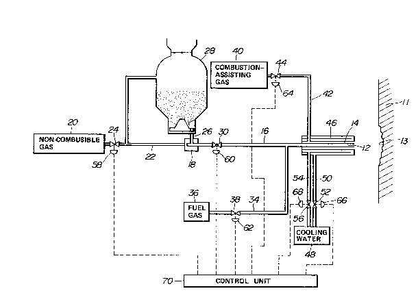
Fig. 1 is a schematic diagramatic illustration
showing the preferred embodiment of a spray coating
apparatus according to the invention:
E~
. .
1~3~
-- 8
Fig. 2 is a graph showing a relationship
between a refractory layer adhering efficiency and
average particle size of a metal particle to be mixed
with a refractory material;
Fig. 3 is a graph showing relationship between
porosity in the refractory layer established and the
average particle size of the metal particle contained in
the mixture,
Fig. 4 is a graph showing a relationship
between a refractory layer adhering efficiency and a
concentration of the metal particle in a mixture of the
refractory material and the particle metal:
Fig. 5 is a graph showing relationship between
porosity and amount of the metal particle in the
refractory material mixture;
Fig. 6 is a graph showing relationship between
porosity in the established refractory layer and oxygen
supply rate;
Fig. 7 is a graph showing relationship
betweeen porosity and average particle si e of the metal
particle when combustioning gas is not supplied;
Fig. 8 is graph showing relationship between
porosity and average particle size of the refractory
artiCle to be utilized in the preferred embodimenr of
Fig. 1;
Fig. 9 is a schematic and diagramatic
illustration showing a modification of the preferred
embodiment of the spray coating apparatus of Fig. 1, and
Fig. lo is a schematic and diagramatix
illustration showing another modification of the
preferred embodiment of the spray coating apparatus of
Fig. 1.
DESCRIPTION OF T~E PREFE:RRED EMBODIMENT
.
Referring now to the drawings, particularly to
Fig. 1, the preferred embodiment of a spray coating
apparatus, according to the present invention. has a
~''33~1~
g
lance 10. The lance 10 has an inner injection nozzle 12
and an outer injection nozzle 14. The inner injection
nozzle 12 extends axially along the center axis of the
lance 10. On the other hand, the outer injection nozzle
14 is in an annular form and arranged coaxially with the
inner injection nozzle 12. The inner and outer
injection nozzles 12 and 14 are directed toward the
surface of a refractory wall or refractory lining 11. In
Fig. 1, the reflactory wall 11 is formed a defect 13 on
the surface. In order to perform repairing for filing
the defect with the refractory material, the inner and
outer injection nozzles 12 and 14 of the lance 10 are
specifically directed to the defect 13 in order to
perform spray coating for filling the defect with the
refractory material.
The inner injection nozzle 12 is connected to
a refractory material supply line 16, which is connected
to an ejector feeder assembly 18 at the end remote from
the lance 10. To the ejector feeder assemhly, a carrier
gas source 20 is connected via a non-combusible gas
supply line 22 and a carrier gas flow control valve 24.
According to the preferred embodiment of the spray
coating apparatus. the carrier gas source 20 is designed
to supply a pressurized inert gas or non-combùsible gas
through the carrier gas supply line 22. On the other
hand, the ejector feeder assembly 18 has a suction pipe
26 inserted into a hopper 28 filled with a mixture of a
refractory material and a fine particle of powder state
combusible metal. A refractory material flow control
~ 30 valve 30 is disposed within the refractory material
supply line 16 for estanlishing and blocking
communication between the lance 10 and the ejector
feeder assembly 18 so as to control supply of refractory
material to the inner injection nozzle 12 of the lance
10.
A branch line 32 of the carrier gas supply
~Z93~
-- 10 --
line 22 is connected to the hopper 28 to introduce
therein the inert or non-combusible gas. Also, a fuel
gas supply line 34 for supplying a non-oxidating fuel
gas. such as propane and the l.ike, is connects the
refractory material supply line 16 at upstream of the
lance lo to a fuel gas source 36. A fuel gas flow
control valve 38 is disposed in the fuel gas supply line
34 for establishing and blocking communication between
the reftactory material supply line 16 and the fuel gas
source 36.
The outer injection nozzle 14 is connected to
a combustion-assisting gas source 40 via a assisting gas
supply line 42 and a assisting gas flow control valve 44
for discharging a oxygen containing combustion-assisting
gas, such as oxyyen gas, air and the like. The
assisting gas flow control valve 44 establishes and
blocks communication between the combustion- assisting
gas source 40 and the outer injection nozzle 14 of the
lance 14.
A cooling water passage 46 is defined within
the peripheral wall of the lance lo or sorrounding the
outer injection nozzle 14. The cooling water passage 46
is connected to a cooling water source 48 via cooling
water supply line 50 and a cooling water supply control
valve 52. ~ drain line 54 with a drain control valve 56
is also disposed between the cooling water passage 46
and the cooling water source 48. There~ore, the cooling
water supplied from the cooling water source 48 is
circulated through the cooling water passage 46 for
cooling the lance 10.
The carrier gas flow control valve 24, the
refractory material flow control valve 30, the fuel gas
flow control valve, the assisting gas flow control
valve. the cooling water supply control valve s2 and the`
drain control valve 56 are respectively associated with
electrically operable actuators 58, 60, 62, 64, 66 and
~L293~1~
-- 11 --
68. Respective actuators 58, 60, 62, 64, 66 and 68 are
controlled by control signals produced by a control unit
70.
In the shown embodiment, the N2 gas is used as
the non-combusible carrier gas. As a fuel gas, propane
gas, acetylene gas and so forth can be used. On the
other hand, as the combustion-assisting gas, oxygen or
atmospheric air as oxygen containing gas is used.
The refractory material is selected among
silica, almina, mullite, chamotte, zilcon, zilconia,
magnesia, magnesite-chrome and so forth, or the
combination thereof. The refractory material is
selected from the above, according to the composition of
the re~ractory wall ll to be treated. The metal to be
mixed with the reEractory material set forth above is
selected among, alumini~m, metal silicon and the
combination thereof. Also, Mg, Mn, FeMn, SiMn, CaSi,
FeSi, FeCr, CaC2 and the combinations thereof can be
used as metal.
AS set forth, when the metal powder in the
average particle size less than 50 ~m in diameter, the
combusibility of the metal powder is substanmtially high
to be easily combustioned. This requires substantially
careful attention in transportation and in spray coating
operation so as to avoid danger in accidental combustion
or back-firing. Even when the substantially high
attention is paid, the operator may still subject
danger. In view of safety in handling and operation,
the average particle size of the metal powder has to be
greater than 5~ ~m. On the other hand, in the shown
apparatus, the metal powder is carried with the
reflactory material by means of the non-combusible gas
flow. Thereforei the maximum size of the metal particle
is limited in view of the flow velocity and pressure of
the non-combusible gas as the carrier gas. Furthermore,
as is well known, the larger particle size metal powder
.~93~
- 12 -
has lower combusibility. Therefore, if the average
particle size of the metal powder becomes excessively
large, it will cause difficulty in generating
satisfactory combustion during spray coating operation.
This, in turn, means that the adherence ability of the
refractory layer to be formed by the spray coating will
be differentiated depending upon the average particle
size of the metal powder. Fig. 2 shows variation of the
adhering ability with respect to various average
particle sizes of the metal powder. It should be noted
that Fig. 2 shows a result of experimentation take place
utilizing powder state aluminium as the material of
combusible metal. In the experimentation, propane gas
is utilized for supplying various caloric values by
combustion thereof. Namely, amount of the propane gas
is adjusted to provide caloric values 0 kcal, 2000 kcal,
3000 kcal and 4000 for 1 kg of the mixture of the
refractory material and the metal particle. In the
mixture, 15~ by weight of the metal powder, i.e.
aluminium powder, is contained. In Fig. 2, line A shows
the variation of the adherence ability (Wt~) of the
refractory layer established when the amount of propane
is adjusted to provide 0 kcal of caloric value.
Likewise, lines B, C and D respectively show adherence
ability at 2000 kcal, 3000 kcal and 4000 supplied by
combustion of the propane gas.
As observed from Fig. 2, when 3000 kcal of
caloric value is supplied, relatively high adherence
ability was obtained when the average particle size of
. . .
the aluminium powderle is less than or equal to 160 ~m.
Namely, the adherence ability at the average particle
size 160 ~m of the aluminium particle with providing the
3000 kcal of calory corresponds to that of the particle
size 20 ~m of the alminium powder provided no calory.
Therefore, in view of the result of experimentation set
forth above, the maximum average size of the metal
~LZ93~
powder is preferred at the average size less than or
equal to 160 ~m.
Fig. 3 shows porosity in the refractory layer
formed in the experimentation set forth above. In Fig.
3, the lines A, B, C and D respectively show porosity of
the refractory layer formed by spray coating operations
with providing calory of 0 kcal. 2000 kcal, 3000 kcal
and 4000 kcal by combustion of the propane gas. As
observed from Fig. 3. while the average particle size in
diameter of the aluminium powder is held smaller than or
e~ual to 160 ~m. the porosity is maintained less than or
equal to 20q~. In view of this, the particle size of the
metal powder is also preferred at the average size less
than or equal to }60 ~m. In Eurther observation in Fig.
3, it would be appreciated that it would be more
preferable to limit the range of average particle size
of the metal powder in diameter less than or equal to
140 ~m. Therefore. in view of the preferred porosity, it
would be appreciated that it is more preferabe to limit
the range of the average metal particle size is 70 ~m to
140 ~m.
Fig. 4 shows variation of adherence ability of
the refractory layer formed by spray coating in relation
to the content of the metal powder. In order to find an
optimum content of the metal powder in the mixure of the
refractory material and the metal powder. an
experimetation was performed. For this experimentation,
the a~erage particle size 80 ~m in diameter of the
aluminium powder is utilzed to be~ mixed with the
refractory material. For experimental spray coating
operation, supply calory was adjusted at lOoo kcal.
As seen from Fig. 4, the adherence ability is
icnreased at substantially high rate according of-
increasing of the content of the aluminium powder upto
lo Wt%. After reaching lo Wt%, increasing rate of the
adherence ability is substantially lowered. In view of
1~3~ ~
- 14 -
the result of experimentation as sho~ln in Fig. ~, it
will be appreciated that satisfactory adherence can be
obtained when the content of the metal powder is greater
than or equal to lo Wt~. On the other hand, as will be
naturally understood, increasing of the amount of the
metal powder increases the cost of spray coating.
Therefore, in view of the cost-vs- performance. the
preferred range of metal powder content is in a range of
10 Wt~ to 30 Wt%.
Fig. ~ shows variation of porosity in the
refractory layer formed by spray coating with various
content of the metal powder. As seen from the graph of
~ig. S, the porosity is held lower than or equal to 20%
when the content of the metal powder in the refractory
material mixture is in a rAnge oE 10% to 30 % by weighk.
This may con~irm that the content of the metal particle
in the range of lo Wt% to 30 Wt% is preferred. In the
further obsevation, it is appreciated that when the
content of the metal powder in the mixture of the
refractory material and the metal powder is higher than
about 15 Wt%, the porosity becomes less than or equal to
10~, In additionally considering the
cost-vs-performance, the further preferred range of the
content of the metal powder is in a range of 13 WT% to
20 WT%-
As will be appreciated, it is preferable to
completely combustion the metal powder to generate
calaric value sufficient for melting or half-melting the
refractory material and to convert the combusible metal
into refractory metal oxide. The particles of metal
oxide in a melt or hald-melt state coat the outer
periphery of the refractory material which is also in
melt or half-melt state. In order to obtain complete
combustion of the combusible metal particle, sufficient
amount of combustion-assisting gas, such as oxygen, air
and so forth, is required.
~L;293~
In order to determine the supply ratio of the
combustion-assisting gas. an experimentation is
performed. In the experimentation. alumina refractory
which has a composition of 85 Wt% of Al2o3, lO Wt% of
Sio2 and remainders of Fe203, CaO. The alumina
refractory is mixed with alumlnium particle having an
average particle size of lOO ~m. The aluminium particle
is contained in the refractory material mixture in a
rate of lO~o by weight. As the combustion-assisting gas,
oxygen was used and as the fuel gas. propane was used.
Amount of propane was adjusted to generate 3500 kcal of
caloric value in total including caloric value generated
by combustion of the aluminium powder.
The graph in Fig. 6 shows variation of the
porosity in the refractory layer formed in the
experimentation in relation to the oxygen supply ratio
relative to the theoritical equivalent amount of oxygen
for oxidation of the aluminium powder. It should be
noted that equivalent amount of oxygen for combustion of
propane gas was neglected from the value in the graph.
As observed from ~ig. 6, porosity of the
refractory layer formed in the aforementioned
experimentation is held less than or equal to 20% when
the supply rate of the oxygen is three-times or more of
the theoritical equivalent amount. The porosity of the
refractory layer can be held lower than or equal to 20%
as increasing the oxygen supply rate upto fifteen-times
of the theoritical equivalent. When the oxygen supply
rate exceeds fifteen-times of the theoritical
equivalent, the porosity again increases. As will be
appreciated herefrom. the oxygen supply rate is
preferably in a range of three-times to fifteen times of
the equivalent amount relative to the amount of the~
aluminium powder in the refractory material mixture. As`
will be further seen from Fig. 6. the further preferable
oxygen supply rate is four-times to fifteen times of the
33~1~
- 16 -
theoritical equivalent.
On the other hand~ as will be easily
appreciated, the adherence ability of the refractory
layer to be formed is variable depending upon the
magnitude of melting of the refractory material. The
melting magnitude of the refractory material will be
increased by increasing the caloric value to be provided
thereto. Therefore, in order to satisfactorily melt the
refractory material, sufficient amount of fuel gas to
generate sufficient caloric value, has to be supplied.
As set forth, in order to obtain satisfactory melting
magnitude, ~000 kcal to 8000 kcal of caloric value is
required in the prior art as set forth above. This
requires large amount of fuel gas to make the spray
coating expensive.
According to the present invention, since the
additional caloric value is provided by combustion of
the metal powder, required fuel amount can be reduced.
In the present invention, the fuel gas amount to be
Supplied in the spray coating operation is set for
providing less than or equal to 5000 kcal of caloric
Value during combustion for 1 kg of refractory material.
More preferable range of caloric value to be generated
~ by combustion of the fuel gas is 2000 kcal to 4000 kcal
: 25 per 1 kg of refractory material. By providing such
reduced amount of fuel gas, the caloric value to be
generated in combustion of the fuel gas in the frame
become insufficient to cause melting of the refractory
material. Therefore, the refractory material discharged
: 30 through the lance lo will be merely heated to be easily
melted by providing additional calory~
In observation of the process of formation of
the refractory layer according to the invention, it was
found that the not molten particles of refractory
~ 35 material contact onto the surface of the reflractory; construction to be treated, with the combustioning
~3~
particles of metal powder. On the surface of the
refractory construction, the metal powder particles
contiune combustion to directly transmit the
combustioning calory to the refractory material. Calory
transmission efficiency from the combustioning metal to
the refractory material is much higher than that
; transmitted from the combustioning gas to the refractory
maetrial. As a result, the retractory material on the
surface of the refractory construction melts and/or
half-melts to successfully adhere on the associated
surface of the refractory construction.
Tf the caloric value sufficient for melting
andtor half-melting the refractory material in the
combustioning frame is provided, part of the molten
refractory material adheres onto the internal periphery
oE the inner nozzle of the lance to cause variation of
the path area of the nozzle. This causes fluctuation of
the injection rate of the refractory material, the metal
~ powder and the fuel gas to vary performcance of the
; 20 spray coating. This will be seen from lines G and H in
Fig. 8. The lines G and H are obtained from the
; experimentation set forth above by providing 5000 kcal
and 6000 kcal of caloric value.
As will be clear herefrom, the preferred range
of the fuel gas supply amount in the present invention
is to generate less than or equal to 5000 kcal, and more
preferably a 000 kcal to 4000 kcal.
Returning to Fig. l, the practical spray
coating operation to ~e taken place by the preferred
embodiment of the spay coating apparatus according to
the invention will be disclosed herebelow.
In order to prevent the refractory wall from
causing spalling, it would be preferable to gradually
and moderately heat the refractory wall in advance of
performing spray coating. Therefore, control unit 70
feeds the control signals to the actuators 62 and 6~.
12~3~14
- 18 -
As a result. the actuators 62 and 64 become active to
open the aasociated fuel gas supply control valve 38 and
the assisting gas supply control valve 44. Therefore,
the fuel gas source 36 and the cornbustion-assisting gas
source 40 are connected to the inner and outer injection
nozzles 12 and 14 of the lance lo. Since the lance lo
is inserted into the substantially high temperature
atmospher in the coke oven, kiln, furnace or so forth,
the fuel gas is burnt or combustioned to establish a
frame directed toward the defect 13 on the refractory
wall 11. By the frame established as set forth above,
the portion of the refractory wall 11 to be treated is
heated beforehand of starting spray coating.
Subsequently, the control signal is
transmitted to the actuator 58 to open the carrier gas
flow control valve 24 to establish communication between
the carrier gas source 20 and the ejector feeder
assembly 18. By opening of the carrier gas flow
control valve 24, the pressurized non-combusible carrier
gas is introduced into the hopper 28 to increase the
internal pressure of the hopper. After the pressure in
the hopper reaches a predetermined value, the control
signal is fed to the actuator 60 to open the refractory
material flow control valve 30. Therefore, pressurized
carrier gas starts to flow through the eiector feeder
aSsembly 18 and the refractory material supply line 16.
During passing of the non-combusible carrier gas through
the ejector feeder assembly 18, the mixture of the
refractory material and the metal powder is drawn into
the ejector feeder assembly and transferred through the
refractory material supply line 16. Therefore, the
refractory material mixture flows through the
reftractory material supply line. Since the fuel gas is
introduced into the refractory material supply line 16
at the position downstream of the refractory material
flow control valve 30 and upstream of the inner
,
:iZ~34:14
- 19 -
injection nozzle 12 of the lance, a combusible mixture
of the refractory material, the combusible metal powder
and the fuel gas is established. The combusible mixutre
containing the fuel gas is transferred into the inner
injection nozzle. Upon injected from the end of the
inner injection nozzle 12, the refractory material
mixture and the fuel gas subject substantially high
atmospher to establish combustion.
At the same time, the combustion-assisting
gas is discharged through the end of the outer injection
nozzle 14 around the frame established by combustion of
the metal powder in the reflactory material mixture and
the fuel gas. By the presence of the combustion-
assisting gas, combustioning frame propagrates. The
refractory material with combustioning metal powder
contacts onto the surface of the refractory wall 11, on
which the defect 13 is formed. At this time, the metal
oxide as a resultant of the combustion may also serve as
the refractory material and mixed with the refractory
material. This increases density of the refractory
material to increase the density of the reflactory layer
formed by the spray coating.
After completing required spray coating
operation, the control signals are transmitted to the
actuators 58 and 60 to close the carrier gas flow
control valve 24 and the refractory material flow
control valve 30. As a result, supply of refractory
materialis shut. At this time, since the fuel gas flow
control valve 38 and the assisting gas flow control
valve 44 are kept open, combustion of the fuel gas is
maintained to enable to gradually and moderately cool
off the refractory wall. This successfully prevent the
refractory wall from causing spalling.
EXAMP~E I
Utilizing the preferred embodiment of the
spray coating appratus of Fig. 1, the repair is
-
93gl4
- 20 -
performed for fire blick construction around a tuyere of
a hot metal ladle having hot metal receiving capacity of
loot. The fire blick was made of high almina material.
Repairing operation is performed by spray coating by
injecting mixture of the refractory material and the
metal particle in amount of 60 kg/h. The flow of the
combustion-assiting gas. i.e. oxygen flow, is
established around the mixture injected.
Alminium powder was used as the combusible
metal component of the mixture. ~aximum particle size
of the aluminium powder was 120 ~m and the average
particle size was 80 ~m. This aluminium powder was
mixed with a alumina refractories having maximum average
particle size of SOO ~m. The alumina refractories has a
composition of 87 Wt% o~ Alao3 and remainders is
constituted of SiO2, CaO, Fe203, The aluminium powder
and alumina refractories were mixed at a mixture ratio
of 20 : 80 by weight.
The wall of the ladle to be repaired was
previously heated by a frame established by combustion
of propane gas (C3H8) as the fuel gas, at a temperature
of 1400 C. After the wall temperature reaches about
1400 C, the mixture was introduced into the lance for
lnjection with N2 gas as the non-combisible carrier gas.
To the flow of the mixture and N2 gas, the propane gas
is introduced in amont of 6.0 m Ih. The combustion-
assisting gas, i.e. oxygen, is also discharged around
the mixture injected. The discharge rate of the
.
combustion-assisting gas was set at 37.5 m3/h. Spray
coating operation was~continued for about lo minutes. As
a result, satisfactory refractory layer could be formed
on the fire blick. Spalling was not observed in the
~J : fire blick. ~urthermore, as observed the established
refractory layer, the layer was firmly adhered on the
-
fire blick.
After completing the aforementioned repairing
3~
operation, the hot metal ladle thus repaired was used to
receive lOot of hot metal at the temperature of 1650 C.
The received hot metal was transported to a station
where continuous casting is performed and poured into a
continuous caster from the ladle. The repaired ladle
could be used for 6 heats of the foregoing operations.
EXAMPLE II
In order to compare the efficiency and
performance of the spray coating according to the
invention, comparative experimentation was performed.
The comparative experimetation has been performed
; without supplying the combustion-assisting gas, such as
oxygen or air, according to the process set out in the
Japanese Patent Second Pulication 49-46364. Fig. 7
shows variation of porosity of the refractory layer
formed d~ring the comparative experimentation. Content
of alimunium powder was varied in various samples to the
rates of lo Wt%. 15 Wt% and 20 Wt%. As will be seen
from Fig. 7, porosity of the refractory layer becomes
zO Smaller as decreasing the average particle size of the
aluminium powder to be contained in the refractory
material mixture.
In the observation of the line B which is
derived from samples containing 15 Wt~ of aluminium
powder, the average particle size of less than or equal
to 20 ~m is required for obtaining the refractory layer
having a porosity less than or equal to 20%.
In order to compare with this, another
.
experimentation was performed with supplying oxygen as
the combustion-assisting gas utilizing the spray coating
appratus of Fig. 1. In the experimentation, propane gas
was used as the fuel gas. Supply amount of propane was
adjusted to supply different caloric values, e.g. 2000
kcal/kg, 3000 kcal/kg and 4000 kcal/kg. lO Wt% of
aluminlum powder was contained in the refractory
material mixture. ~s will be seen from Fig. 8, in this
IL2~3~
- 22 -
case, the porosity of the refractory layer formed in the
experimentation could be maintained less than or e~ual
to 20%, when the average particle size of the aluminium
powder was in a range of 40 ~m to 160 ~m.
This confirms that, in the spray coating
method as proposed in the present invention, greater
average particule size of metal powder can be used for
performing spray coating without causing siginificant
difference to that obtained in the conventional process
utilizing substantially small particle size of metal
powder. Therefore, the present invention assures safety
spray coating operation.
In addition, according to the ivnention, since
the metal particle is carried by non-eombusible earrier
Is gas, combustion of the metal powder within the
refraetory material supply line can be successEully
prevented.
Though the foregoing preferred embodiment of
the spray eoating apparatus of Fig. 1, employs the inert
and/or non-combusible gas as carrier gas for
transporting the powder state mixture of the refractory
material and the metal powder. it would be possible to
earry the mixture with any non-oxidation gas. Namely,
the fuel gas, sueh as propane gas, ean be used for
transporting the powder state mixture. Therefore, the
appratus of Fig. 1 ean be modified as shown in Figs. 9
and 10.
In a modification of Fig. 9, the ejeetor
feeder assembly 18 s connected to a fuel gas source 36
via a fuel gas supply eontrol valve 80. The
non-combusible gas source 20 is connected to the
internal space of the hopper 28 via the non-combusible
gas flow eontrol valve 82. The fuel gas supply control
valve 80 and the non-combusible gas flow control valve
3~ 82 are respectively associated with valve actuators 84
and 8~ which are, in turn, connected to the control 70.
12~3'~i4
- 23 -
Other construction of the modification of Fig. 9 is
identical to that illustrated in Fig. 1. Therefore, the
disclosure for respective feature in the common
construction is neglected in order to keep the
recitation concise enough to avoid unnecessary
confusion.
In the shown construction~ the non-combusible
gas is introduced from the non-combusible gas source
into the hopper 28 to pressurize the mixture of the
refractory material and the metal powder in the hopper
28. On the other hand, the fuel gas is supplied to the
ejector feeder assembly 18 from the fuel gas source 36
for drawing the mixture in the hopper to the refractory
material supply line 16. By introducing the mixture in
the refractory material supply line 16, a combusible
mixture oE the reEractory material, the metal powder and
the fuel gas is established. Therefore, the refractory
material and the metal powder are carried by the fuel
gas flow to the inner nozzle 12 of the lance lo.
~ 20 On the other hand, in another modification in
Fig. lo, the fuel gas source 36 is connected to the
hopper via the fuel gas supply contr~ol valve 80.
Therefore, in this arrangement, the combusible mixture
is established in the hopper 28 and forced to flow
through the refractory material supply line 16 by the
pressure in the hopper.
In this case, a brantch passage 90 as shown by
phantom line is provided for connecting the refractory
material supply line 16 and the fuel gas source 36 via
three-way valve 92 so that combustioning frame of solely
the fuel gas can be established for moderately
warming-up and cooling-off the surface to be treated
before and after spray coating operation. With the~
foregoing construction, the three-way valve may connect`
the fuel gas source to the refractory material supply
line via the branch passage while the spray coating is
- ~ . .
~2~3~ ~
- 24 -
not performed so that the fuel gas can be directly
supplied to the inner nozzle. On the other hand, when
spray coating is to be performed, the valve position of
the three-way valve may be switched to connect the fuel
gas source to the hopper. Furthermore. so that the fuel
gas in the appratus can be safely removed when the
refractory material and/or metal powder to be used are
,
to be changed, an inert or non-combusible gas source is
connected to the fuel gas passage connecting the fuel
gas source and the hopper, as illustrated by the phantom
line in Fig. lO. In this case. a three-way valve 94 may
.
also be provided for selectively connecting the hopper
to the fuel gas source and the non-combusible gas source
20.
.
It should be appreciated that, in both
modifications set forth above, it is essential to use a
... . . . .
fuel gas which does not contain oxygen so as to avoid
. .
danger of accidental combustion of the metal powder.
.. .. . . . . . . . ..
~ While the present invention has been disclosed
.. . . . . . .. .. .. .. . . .. . .. . . .
in terms of the preferred embodiment in order to
facilitate better understanding of the invention, it
.. .. ..
should be appreciated that the invention can be embodied
in various ways without departing from the principle of
.
the invention- Therefore, the invention should be
Understood to include all possible embodiments and
modifications to the shown embodiments which can be
. ... . . .
embodied without departing from the principle of the
... . . . . . .
~ invention set out in the appended claims.
:
~ 35
.. : ': -' ``:: - : .::. . ` .. ~