Note: Descriptions are shown in the official language in which they were submitted.
"
.
FAUCET SPRING
Background of the Invention
I. Field of the Invention
This invention relates to a coil spring for a faucet
assembly and', in particular, to a faucet spring which in
addition to urging the seal member into contact with the
movable valving member prevents damaging debris from
contacting the valving member.
II. Descri~tion of the Prior Art
One of the features of a washerless faucet is the
resilient seal element which cooperates with the valving
member to ensure complete shut-off of fluid flow when the
valve is moved to the off position. Gensrally, the seal
element is seated within a smaller secondary bore offset
from the center of the main bore which houses the valving
member. In order to maintain sealing contact between the
seal element and the valving member, means are normally
provided to urge the seal against the bo~tom of the
valving member. Such means may be provided by the
resilient properties of the seal wh~n the seal element is
axially compressed within the sec~nc2_y bo~e.
Alterna~ively, a spring may be utilized to urge the seal
upwardly to ensu_e engagemen_.
Because the seal e~ement and/or ~he spr_ng form a
tubular low passage leading to _he valving member, de~ris
found in the supply lines of the fauce~ will be forced
through the passage under the fo~ce of the water pressure
~g'
~2934~34
into contact with the valving member. Certain types of
debris can damage the valving member or jam its operation
as it is rotated.
Such damaging debris can even be in the lines
unnoticed before the new washerless faucet is installed.
Oftentimes the retaining screws for a valve washer in an
old faucet can loosen and drop into the supply line.
After the old faucet is replaced by the new washerless
faucet and the water is turned on, the screw can be forced
up against the valving member by the pressure of the fluid
flow resulting in damage to the valve. When the water
pressure is turned off to investigate the malfunction or
to replace the valve, the screw can fall back into the
supply line unnoticed. This routine can occur repeatedly
until the frustrated consumer gives up on the new fauc~t
assembly. Many times the only evidence of the recurring
problem is the set of thread marks left on the valve
member by the screw. To date no means have been developed
to prevent such large debris from engaging the valve seat
while maintaining the efficient operation and low cost of
the washerless faucet valve cartridge.
Summarv of the Present Invention
~ he present invention overcomes the disadvan.ages of
the prior known faucet assemblies by providing a fauce~
spring adapted to urge the seal membe- into con~act with
the valving member while also blocking large debris, such
as old loose valve washer screws, from engaging the
valving member.
~ he ~aucet assembly embodying the present invention
in-ludes a valve body having a first a~ial bore and a
second smaller bore offset from the a~is of the valve
body. A valving member is rotatably disposed within the
first bore of the valve body while a seal element is
seated within the offset secondary bore. The secondary
bore, which forms the inlet passage for the valve,
comprises a lower passageway and an upper counterbore
within which the seal element is disposed. In order to
urge the seal upwardly to maintain sealing contact with
the rotatable valving member, a spring extending from the
shoulder formed by the counterbore and in contact with the
seal element is utilized. Unlike past known faucet
springs, however, the spring of the present invention
includes means for reducing the cross-sectional area of
the flow passage through the spring and seal in order to
block any large debris from flowing therethrough.
The faucet spring is in the nature of a coil spring
and generally has a frusto~conical configuration with a
bottom diameter greater than the top diameter. ln this
manner, the bottom of the spring is adapted to securely
engage the annular shoulder formed by the counterbore
while the frusto-conical shape and the top of the spring
facilitates engagement with the seal element. Formed at
the bottom as an integral extension of the coil spring is
a blocking member which extends into the central passage
of the spring and seal to reduce the dimensions of the
opening although not significantly reducing the flow rate
therethrough. In a first preferred embodiment of the
spring, the blocking member is formed by a reduced
diameter coil of the spring. In a second embodimen_, the
blocking member consists of a cross member ben~ across the
large diameter opening of the spring. Thus, bo'h
emboàiments provide integral s'ructu-al means fo~
preventing large debris found in the supply line from
being Ccrced in~o the faucet housing.
Other objects, features, and advantages of the
invent_on will be apparent from the following cetailed
,~ ~
~3~9~L
description taken in connection with the accompanying
drawings.
Brief Description of the Drawing
The present invention will be more fully understood
by reference to the following detailed description of a
preferred embodim~nt of the present invention when read in
conjunction with the accompanying drawing, in which like
reference characters refer to like parts throughout the
view and in which:
; FIGURE 1 is a cross-sectional view of a faucet valve
assembly embodying the faucet spring of the present
invention;
FIGURE 2 is an elevated perspective of a first
embodiment of the faucet spring;
FIGURE 3 is a side view of the faucet spring of Fig.
lS 2;
FIGURE 4 is a bottom end view of the~faucet spring of
Fig. 2;
FIGURE 5 is a side view of a second embodiment of the
faucet spring embodying the presen~ invention; and
PIGURE 6 is a bottom end view of the faucet spring of
Fig. 5.
.
Detailed Descri~tion of a Preferred
Embodiment of the Present Invention
Referring first to Figure 1, there is shown a fauce'
valve assembly lO embodying the present invention and
gent~rally comprisinS a valve body 12 and a valving member
14 rotatably disposed within the valve body 12 and
connected to an operating member 16 for selectively
,
~L2~ 49~
rotating the valving member 14 within the valve body 12 to
control the water flow through the valve 10. The valve
assembly 10 is connected to a supply :line 18 which
communicates with an inlet passageway 20 ~f the valve body
12. The valve body 12 also includes an outlet passage 22
which fluidly communicates with the faucet spout to
deliver water to the user. Fluid flow through the valve
assembly 10 is controlled by rotating the valving member
14 within the valve body 12 to selectively bring the fluid
passageway ~4 into and out of registry with the inlet
passageway 20 and the outlet passage 22. As is shown in
~ig. 1, the inlet passageway 20 is smaller than the main
bore 26 and offset from the rotational axis thereof. As a
result, as the valving member 14 is rotated the port 28
1~ formed in the valving surface 30 will be brought into
(Fig. 1) and out of registry with the inlet passageway 20.
In order to provide a fluid seal between the inlet
passageway 20 and the valving surface 30 of the valving
member 14, a substantially tubular seal element 32 is
seated within the inlet passageway 20.~:In a preferred
embodiment of the valve assembly lQ, the seal element 32
is disposed wi'hin a counterbore 34 of the passageway 20
to maintain the proper position of the seal element 32
between the valving su~'ace 30 and an annular shoulder 36
of the counterbore 34.
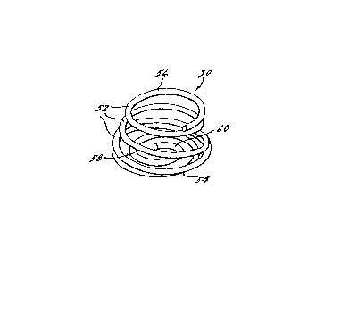
In the embodiments of ~he presen~ invention, a fauce'
sp~_ng 50 is utilized tG bias the seal element _2 against
the valving surface 30 of the valving member 14. As
illu t-ated in ~igures 1-4, the fauce' spring 50 is in the
fo-m of a compressible coil spring having a plu-ali~_y of
helical coils 52 wi~h a cen-ral passage extending through
the spring 50. The fauce' sp-ing 50 of the present~
invention preferably has a substantially frusto-conical
configuration with a lower end 5 of greater diameter than
12~3~9~
the upper end 56 of the spring. The faucet spring 50 is
disposed within the counterbore 34 of the inlet passageway
20 such that the lower end 54 of the spring 50 engag~s the
annular shoulder 36 of the counterbore 34. The upper end
56 of the spring 50 and the general frusto-conical shape
thereof act against the seal element 32 to urge it into
contact with the valving member 14. When fluid flow is
initiated the water flows through the inlet passageway 20
and the passage through the seal and spring.
In addition to the general coil structure of the
faucet spring 50, the spring includes means 58 for
preventing large debris components from traveling through
the central passage of the seal and spring into damaging
contact with the valving member 14. Debris, such as old
valve washer screws 100 from previous faucet assemblies,
can be forced up the supply line 18 under.the pressure of
the water thereby damaging the valving member 14. The
preventing means 58 stops such debris from contacting the
valving member 14. In a first embodiment of the present
invention shown in Figs. 2-~, the preventing means 58
comprises a reduced diameter coil 60 formed as an integral
extension of the main coils 52 of the spring. In addition
to maintaining the general helical shape of the coil
sp-ing ~hereby reducing manufacturing costs, the reduced
coil effectively reduces the dimensions of the bottom
opening of the spring 50 to block debris wi'~hout
signi'ican~ly reducing flow volume through the iniet
passageway 20. This is because any flow restriction
occurs at the upper end of the spring 50 firs. by the
reduced flow passage fo~med by 'he seal 32 and then the
inlet por, 28. The lower end 5. of ~he spring 50 is, in
essence, oversized to accommodate the required ~low ra'e
and, thus, the blocking means 58 does not significantly
reduce the rate o~ fluid flow through the valve lC.
3 Z~3~9~
- 7 - 68432-59
In a second embodiment of the invention shown in Figures
5 and 6, the preventing means comprises a cross member 62 which
bisects the bottom opening of the spring 50. Again, while reduc-
ing the dimensions of the passage through which debris may pass,
fluid flow is not significantly reduced. The cross member 62 is
an integral extension of the coil spring and is formed simply by
bending the end portion of the spring perpendicularly across the
bottom face of the spring.
Thus, the present invention provides simple, economical
to manufacture and efficient means for preventing damaging debris
from coming into contact with the valving member. Although the
present invention has been described in conjunction with a
rotatable valve assembly, the faucet spring 50 can similarly be
utilized in conjunction with a ball-type valving member wherein
the spring 50 urges the seal element against the valving surface
of the ball-type valving member.
.