Note: Descriptions are shown in the official language in which they were submitted.
12936S7
Description
ImPacting Mechanism
Technical Field
This invention relates to a mechanical
impacting mechanism used to impact a surface and more
particularly to an impacting mechanism for breaking
composite material into a plurality of pieces.
Background Art
A known demolition apparatus has a housing
which is attached to a boom. The actuator plunger is
mounted within the housing for axial movement with
respect to the housing. The power plunger is mounted
within the housing in adjacent spaced relation to the
actuator plunger for movement with respect to the
housing and the actuator plunger. Th~ demolition
apparatus has a latch which releasably connects the
actuator plunger to a fixed collar on the power
plunger. A problem associated with such demolition
apparatus which has the actuator plunger and the power
plunger in spaced relation is that fragments of the
impacted material will be thrown outwardly from the
impact of the power plunger against the surface.
Another problem associated with such demolition
apparatus is having a single latch which puts side
loads on the actuator plunger and the power plunger,
thus causing bending and wear on the plungers.
The present invention is directed to
overcoming one or more of the problems as set forth
above.
d~
1~3657
-2-
Disclosure of the Invention
In one aspect of the present invention an
impacting mechanism is adapted to be mounted on a
movable manipulator for movement relative to a surface
to be impacted. A guide structure is adapted to be
connected to the manipulator. An actuator is movably
supported by the guide structure and has an end
portion adapted to contact the surface to be impacted.
An impact plunger is movably supported relative to the
guide structure and the actuator in generally centered
relation within the actuator. Resilient means between
the guide structure and the impact plunger biases the
impact plunger toward the end surface of the actuator.
A means releasably couples the actuator and the impact
plunger so the resilient means is compressed in
response to the guide structure being moved toward the
end surface of the actuator. A means releases the
coupling means when the guide structure reaches a
predetermined distance from the end surface of the
actuator so that the resilient means drives the impact
plunger toward the surface to be impacted.
An impacting mechanism having an impact
plunger which is disposed in a generally centered
relation within the tubular actuator shields the
impact to contain any fractured pieces of material and
provides a plurality of latch assemblies to equalize
loading on the impact plunger and the tubular
actuator.
Brief DescriPtion of the Drawings
Fig. 1 is a sectional view showing the
internal elements of an embodiment of the present
invention.
1Z936S'7
-3-
Fig. 2 is an enlarged view of a latch
assembly as indicated by line II in Fig. 1.
Fig. 3 is a sectional view taken along line
III-III of Fig. 1.
Fig. 4 is an enlarged view of one latch
assembly.
Fig. 5 is an enlarged sectional view showing
the adjustable end of the actuator.
Fig. 6 is a diagrammatic sectional view
showing an alternate design.
Best Mode for CarrYing Out the Invention
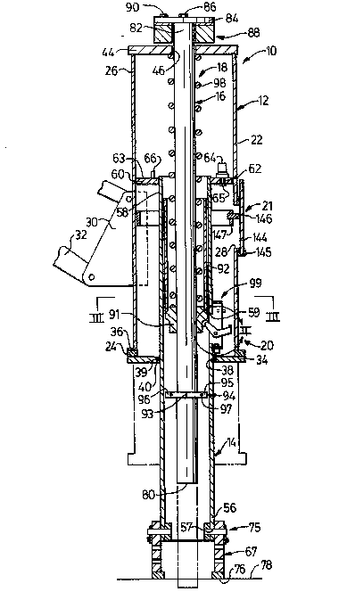
As shown in Fig. 1 of the drawings, an
impacting mechanism 10 include~ a guide structure 12,
an elongate tubular actuator 14, an impact plunger 16,
a resilient means 18, a releasable coupling means 20,
and a releasing means 21.
The guide structure 12 includes a
cylindrical housing 22 having a first end portion 24,
and a second end portion 26, and a plurality of
circumferentially equally spaced apertures, one of
which is shown at 28, intermediate the end portions
24,26. A bracket 30 of suitable construction is
fixedly attached to the cylindrical housing 22 and
connects the cylindrical housing to a movable
manipulator 32, such as a boom or suitable linkage of
an industrial vehicle.
A first end plate 34 is releasably attached
to the first end portion 24 of the cylindrical housing
lZ93657
--4--
22 by a plurality of fasteners, such as bolts 36~ The
end plate 34 has a bore 38 with a counterbore 39. A
bearing 40 is positioned in the counterbore 39 of the
end plate 34.
A second end plate 44 is suitably fastened
to the second end portion 26 of the cylindrical
housing 22 and has an aperture 46 therethrough.
The tubular actuator 14 is coaxially
telescopically disposed within the guide structure 12
and is movably supported by the bearing 40 within the
first end plate 34 thereof. The tubular actuator 14
includes a first end portion 56 with a pair of
circumferentially equally spaced mounting holes 57, a
second end portion 58, and a plurality of
circumferentially equally spaced apertures, one of
which is shown at 59, intermediate the first and
second end portions 56,58. An annular guide 60 having
an aperture 62 and an upper surface 63 is attached to
the second end portion S8 of the tubular actuator 14.
A resilient bumper 64 is releasably secured on the
upper surface 63 of the guide 60 by a bolt 65 passing
through the aperture 62. A plurality of stop rods 66
is attached to the upper surface 63 of the guide
assembly 60.
As best shown in Fig. 5, the tubular
actuator 14 includes an adjustable collar 67 attached
to the first end portion 56 thereof and having a
plurality of vertically spaced pairs of adjusting
apertures 68. A pair of pins 70, each having an
anchor plate 72 secured to one end thereof is
positioned in the uppermost pair of one of the
adjusting apertures 68 and the pair of mounting holes
~ ~ Z9365'7
57 in the first end portion 56 of the tubular actuator
14 to releasably secure the adjusting collar 67
thereto. A bolt 74 releasably secures each of the
anchor plates 72 to the adjustable collar 67 to retain
the pins. The adjustable collar 67 has an end surface
76 adapted to contact a surface 78 which is to be
impacted and defines an impact area 79 within
adjustable collar 67. The adjustable collar 67,
adjusting apertures 68, pins 70, and bolts 74 provide
a means 75 to adjust the end surface 76 relative to
the guide structure 12.
The impact plunger 16 is telescopically
disposed in generally centered or coaxial relation
within the tubular actuator 14. The impact plunger 16
has an end surface 80 adapted to impact the surface
78, and an oppositely disposed end portion 82
extending through the aperture 46 of the second end
plate 44 of the guide structure 12. A plate 84 is
secured to the second end portion 82 of the impact
plunger 16 by a plurality of bolts 86. An annular
resilient bumper assembly 88 is attached to the plate
84 by a plurality of bolts 90 in downwardly extending
relation as pictured in Fig. 1 toward the end plate
2S 44. Alternatively, the bumper assembly 88 may be
attached to the second end plate 44, or the bumper
assembly 88 may loosely encircle the impact plunger 16
and rest on the second end plate 44. A spring
abutment collar 91 is fixedly attached to the impact
plunger 16 intermediate the first and second end
portions 80,82. A tube 92 attached to the collar 91
extends upwardly to enclose and position the resilient
means 18. A groove 93 is provided intermediate the
collar 91 and the end surface 80 of the impact plunger
16. An annular guide ring 94 is removably attached in
1293657
-6-
the groove 93 of the impact plunger 16. The guide
ring 94 induces a first semicircular member 95 and a
second semicircular member 96 encircling the impact
plunger 16 and disposed in the groove 93 and is
maintained in position by bolts, one of which is shown
at 97,
The resilient means 18, in this specific
embodiment a coil spring 98, encircles the impact
plunger 16 and is positioned between and confined by
the collar 91 of the impact plunger 16 and the second
end plate 44 of the guide structure 12.
As best shown in Figs. 2, 3, and 4, the
releasable coupling means 20 includes a plurality of
circumferentially equally spaced latch assemblies 99
connected to the tubular actuator 14.
Each of the latch assemblies 99 includes a
mounting assembly 100 having a first side plate 102,
with an aperture 103, and a second side plate 104,
with an aperture 105 and a tang 106. The side plates
102,104 are spaced apart and secured in one of the
apertures 59 of the tubular actuator 14. An upper
plate 107 is secured to the side plates 102 and 104.
A lower plate 108 is also secured to the side plates
102 and 104. A bellcrank 110 is pivotally attached
between the plates 102 and 104 by a pin 112 positioned
in the apertures 103,105 of the side plates 102,104.
The bellcrank 110 has an inwardly projecting first arm
portion 113 and an outwardly projecting second arm
portion 114. The first arm portion 113 has a
bifurcated end portion 116. A roller 118 is
positioned within the bifurcated end portion 116 and
rotatably connected thereto by a pin 120. A lug 122
-
lZ93657
is secured to the second arm portion 114 of the
bellcrank 110. A spring 124 is connected between the
lug 122 of the second arm portion 114 of the bellcrank
110 and the lug 106 of the side plate 102. A
S resilient bumper 127 is attached under the lower plate
108 by a bolt 128.
The releasing means 21 includes a plurality
of circumferentially equally spaced plates, one of
which is shown at 144, suitably attached to the
cylindrical housing 11 by a plurality of fasteners,
one of which is shown at 145. Each plate 144 has an
abutment member 146 which extends through the aperture
28 into the cylindrical housing 22 a predetermined
distance. An annular trip ring 147 is suitably
attached to the abutment members in alignment to
engage the second arms 114 of the bellcrank.
In Fig. 6 an impacting mechanism 148 of an
alternate design is shown. Elements which are the
same in both embodiments will be described with a
reference having a prime. The impacting mechanism 148
includes a guide structure 149, an elongate tubular
actuator 151, an impact plunger 153, a resilient means
18', a releasable coupling means 157, and a releasing
means 159.
The guide structure 149 includes a
cylindrical housing 161 having a first end portion
163, and a second end portion 165, and a plurality of
circumferentially equally spaced elongate vertical
slots 166 intermediate the end portions 163,165. An
end plate 167 is suitably attached to the second end
portion 165 of the cylindrical housing 161. The end
plate 167 has a hole 168. A bracket 30 of suitable
3657
-8-
construction is fixedly attached to the housing 161
and connects the housing 161 to a movable manipulator
32'.
The tubular actuator 151 is telescopically
disposed in generally centered and coaxial relation
with the guide structure 149. The tubular actuator
151 has an end surface 169 adapted to contact a
surface 78' which is to be impacted, an oppositely
disposed end portion 171, and a plurality of
circumferentially equally spaced elongate vertical
slots, onè of which is shown at 173, are positioned
intermediate the end surface 169 and the end portion
171 in alignment with the slots 168 in the guide
structure 149. The end surface 169 defines an impact
area 79' within the tubular actuator. A second
elongate vertical slot 174 is positioned intermediate
the end surface 169 and end portion 171 allowing for
relative movement of the bracket 30' and the tubular
actuator.
The impact plunger 153 is telescopically
disposed in generally centered or coaxial relation
with the tubular actuator 151. The impact plunger 153
has an end surface 175 adapted to impact the surface
78' and end portion 177 extending upwardly through the
hole 167 of the end plate 166. A collar 178 is
fixedly attached to the impact plunger intermediate
the end surface 175 and the end portion 177. The
collar 178 has an upwardly inward inclined surface
179.
The resilient means 18', in this specific
embodiment a coil spring 98', encircles the impact
plunger 153 and is positioned between the collar 178
3GS7
_~_
of the impact plunger 153 and the end plate 166 of the
guide structure 149.
The releasable coupling means 157 includes a
plurality of circumferentially equally spaced latch
assemblies, one of which is shown at 180, connected to
the tubular actuator 151.
Each of the latch assemblies 180 includes a
bracket 182 suitably attached to the tubular actuator
151. A latching lever 184 has a hook portion 185 with
a lower curvilinear surface 186 extending through the
slots 173 and 168 to the interior of the guide
structure 149 and is pivotally attached to the bracket
182 by a pin 187. A resilient means 188, in this
specific embodiment an elastomeric ring 189, biases
the latching levers 184 inward selectively to engage
the collar 178 on the impact plunger 153.
The releasing means 159 includes an abutment
surface 190 formed by the slots 168 in the guide
structure 149.
Industrial ApPlicability
In the impacting process of the preferred
embodiment the movable manipulator 32 is used to move
the impacting mechanism 10 toward the surface 78 which
to be impacted. The tubular actuator 14 and impact
plunger 16 extend downwardly from the first end
portion 24 of the guide structure 12 as shown by solid
lines in Fig. 1. In this position, the first end 80
of the impact plunger 16 is spaced upwardly from the
end surface 76 of the adjustable collar 67. As the
impacting mechanism 10 is moved downward, the end
surface 76 of the adjustable collar 67 on the tubular
657
--10--
actuator 14 contacts the surface 78 thereby stopping
its downward movement. As the guide structure 12
continues to be moved downward, the springs 124 pivot
the bellcranks 110 inwardly around the pins 112 to
position the rollers 118 for engagement with the
collar 91 on the impact plunger 16. As the guide
structure 12 and the impact plunger 16 continue to be
moved downward the collar 91 contacts the rollers 118
and releasably couples the impact plunger 16 to the
tubular actuator 14, thereby stopping downward
movement of the impact plunger 16. The continued
downward movement of the guide structure 12 relative
to the impact plunger 16 and the tubular actuator 14
compresses the spring 98 between the collar 91 and the
second end plate 44. Downward movement of guide
structure 12 a predetermined distance relative to the
tubular actuator generally illustrated by the broken
lines causes the annular trip ring 147 of the
releasing means 21 to engage the bellcranks 110.
Continued downward movement of the guide structure 12
and annular trip ring 147 pivots the bellcranks 110
outwardly around the pins 112 against the force of the
springs 124, until the rollers 118 are disengaged from
the collar 91 on the impact plunger 16. When the
rollers 118 disengage from the collar 91 energy of the
spring 98 is released and immediately drives the
impact plunger 16 downward at a high rate of speed and
high force. The impact plunger 16 impacts the surface
78 within the impact area 79 of the adjustable collar
67 of the tubular actuator 14. Downward movement of
the guide structure 12 is stopped by the second end
plate 44 engaging and deforming the bumper 64 and
contactin~ the stop rods 66, thus avoiding overrunning
of the trip ring 147 beyond the bellcranks 110. When
the impact plunger 16 breaks through the surface 78,
-- lZ93657
as shown by phantom lines in Fig. 1, downward movement
of the impact plunger 16 is stopped by cushioned
engagement between the resilient bumper 88 and the
second end plate 44 of the guide structure 12.
The impacting mechanism 10 is then raised by
lifting the guide structure 12. Upward movment of the
guide structure 12 also raises the impact plunger due
to the engagement between the bumper 88 and the second
end plate 44. The gravitational weight of the tubular
actuator 14 causes it to remain in contact with the
surface 78 during the initial movement of the guide
structure 12 and the impact plunger 16. As the trip
ring 147 becomes disengaged from the bellcranks 110,
the springs 124 pivot the bellcranks 110 inwardly
around the pin 112 until the rollers 118 contact the
sleeve 142. Upward movement of the impact plunger 16
relative to the tubular actuator 14 causes the rollers
118 to roll on the sleeve 142 until they reach the
collar 91. The springs 124 then pivot the bellcranks
110 further inwardly to position the rollers 118 for
engagement with the collar 91. Continued upward
movement of the guide structure 12 and the impact
plunger 16 eventually causes the first end plate 34 to
engage the resilient bumper 127 thereby also raising
the tubular actuator 14 in unison with the guide
structure 12 and the impact plunger 16. With the
tubular actuator 14 and the impact plunger 16 coupled
together the impact process is repeated to impact the
surface 78 at adjacent locations.
In the impacting process of the alternate
embodiment, the movable manipulator 32' is used to
move the impacting mechanism 148 toward the surface
78' which is to be impacted. As the impacting
l;~ S'7
-12-
mechanism 148 is moved downward, the end surface 169
of the tubular actuator 151 contacts the surface 78'
thereby stopping its downward movement. The
elastomeric ring 189 pivots the latching levers 184
inwardly around the pin 187 to position the hook
portion 185 for engagement with the collar 178. As
the guide structure 149 and the impact plunger 153
continue to be moved downward, the hook portions 185
of the latching levers 184 engage the collar 178 on
the impact plunger 153 to releasably couple the impact
plunger 153 to the tubular actuator 151, thereby
stopping downward movement of the impact plunger 153.
The continued downward movement of the guide structure
149 relative to the impact plunger 153 compresses the
spring 98' between the collar 178 and the end plate
166. Downward movement of the guide structure 149 a
predetermined distance relative to the tubular
actuator 151 causes the abutment surfaces 190 of the
releasing means 159 to engage the latching levers 184.
Continued downward movement of the guide structure 149
pivots the latching levers 184 outwardly around the
pins 186, against the force of the elastomeric ring
189, until the hook portion 185 of the latching levers
184 are disengaged from the collar 178. This releases
the energy of the spring 98' and immediately drives
the impact plunger 153 downward. The impact plunger
153 impacts the surface 78' within the impact area 79'
of the tubular actuator 151.
The impacting mechanism 147 is then raised
upward lifting the guide structure 149 and the impact
plunger 153. The gravitational weight of the tubular
actuator 151 causes it to remain in contact with the
surface 78' during the initial movement of the guide
structure 149 and the impact plunger 153. Upward
1~3~57
-13-
movement of the impact plunger 153 relative to the
tubular actuator causes the hook portion 185 to
contact the collar 178. Contact between the
curvilinear surface 186 of the hook portion 185 and
the inclined surface 179 of the collar 178 causes the
latching levers 184 to pivot outwardly against the
force of the elastomeric ring 189. When the hook
portion 185 is moved down past the inclined surface
179, the elastomeric ring 189 pivots the latching
levers 184 inwardly around the pin 187 to engage the
collar 178. With the latching levers 184 engaged with
the collar 178 the impacting process is repeated to
impact the surface 78' at adjacent locations.
An impacting mechanism 10 of this design
disposes the impact plunger 16 in a generally centered
relation within the tubular actuator. Thus, the
impact plunger 16,153 impacts the surface 78,78'
within the contact area of the tubular actuator
14,151. The impact is shielded and prevents fractured
pieces from flying away and hitting surrounding
objects. Having a plurality of circumferentially
equally spaced latch assemblies 99,180 equalizes the
loads on the tubular actuator and the impact plunger,
thus avoiding side loads which cause bending and wear
on the actuator 14 and plunger 16.
Other aspects, objects and advantages of
this invention can be obtained from a study of the
drawings, disclosure, and the appended claims.