Note: Descriptions are shown in the official language in which they were submitted.
~ ()6
TAMPER EVIDENT OPTICALLY VARIABLE
DEVICE AND ARTICLE UTILIZING THE SAME
This invention relates to a tamper evident optically
variable device and to an article utilizing the same.
Because of tampering with certain consumer-type prod-
ucts, there has been an attempt to make such products
more tamper proof, or in other words, tamper resistant.
Even though many changes have been made to make consum-
er type products more tamper resistant, the tamper
resistant packaging provided still can be violated. In
view of the fact that making packaging more tamper
proof is expensive and often makes the consumer type
products more difficult to utiliæe by the consumer,
there is a need for a different approach to attempt to
solve the problems. Thus for example, rather than
attempting to make the consumer type products more
tamper resistant, an alternative approach which may be
preferable is to make the package in such a way 80 that
if tampering occurs it will be evident to the consumer
at the point of sale. There is therefore a need for a
device which can be utilized on articles such as
packages and containers which will make it apparent to
the consumer at the point of sale if tampering has
occurred.
A-43778
--2--
In general, it is an object of the invention to provide
a device which can be utilized with packaging to
indicate to the consumer when tampering has occurred.
Another object of the invention is to provide a device
of the above character which is an optically variable
device.
Another object of the invention is to provide a device
of the above character which can be utilized in con-
junction with containers.
Another object of the invention is to provide a device
of the above character which can be rapidly incorporat-
ed in packaging utilizing conventional packaging
e~uipment.
Another object of the invention is to provide a device
of the above character in which there is a color shift
with angle change.
Another ob;ect of the invention is to provide a device
of the above character in which the angle shift proper-
ties are destroyed when the integrity of the packaging
has been violated.
Additional objects and features of the invention will
appear from the description in which the preferred
embodiments are set forth in detail in conjunction with
the accompanying drawings.
Figure 1 iB a perspective view of a package and con-
tainer of the present invention incorporating a tamper
evident optically variable device.
A-43778
7()~
--3--
Figure 2 is a perspective view of a package containing
another embodiment of the present invention.
Figure 3 is a cross-sectional view of a tamper evident
optically variable device utilized on a container such
as a bottle incorporating the present invention.
Figures 4, 5 and 6 are cross-sectional views of three
different designs for tamper evident optically variable
devices for use in a package.
Figure 7 is a partial cross-sectional view showing the
upper portion of a container having an optically
variable device mounted thereon.
Figure 8 is a cross-sectional view similar to Figure 7
but showing a transparent cap mounted on the container.
Figure 9 is a cross-sectional view showing the manner
in which the optically variable device incorporating
the present invention can be destroyed.
Figure 10 is a partial cross-sectional view of a con-
tainer utilizing a tamper evident optically variable
device and also utilizing a shrink wrap fitting.
In general the tamper evident optically variable device
of the present invention is comprised of an optically
variable device having at least first and second layers
which provide the optically variable device with
optical shifting properties with angle. A release
layer is disposed between the first and second layers
of the optically variable device to permit the first
and second layer~ of the optically variable device to
A-43773
06
--4--
be separated to destroy the optical shifting properties
of the optically variable device.
The article which utilizes the tamper evident optically
variable device has first and second parts which are
movable with respect to each other. The tamper evident
optically variable device has its first and second
layers secured respectively to the first and second
parts of the article so that when the first and second
parts of the article move with respect to each other,
the release layer permits the movement of the first and
second layers with respect to each other to destroy the
optical shifting properties of the optically variable
device.
More particularly as shown in the drawings, the tamper
evident optically variable device and the article
utilizing the same as shown in Figure 1 consists of a
container package 11. The container package 11 con-
sists of a box 12 which contains therein a bottle 13
having a cap 14 threadedly mounted thereon. The bottle
13 can be formed of any suitable material such as glass
or plastic. Similarly, the cap 14 can also be formed
of a suitable material such as metal or plastic. As
shown the bottle 13 has a conventional cylindrical
configuration. The box 12 also is of a conventional
cardboard type and is of a generally rectangular
configuration. The box i6 formed in a conventional
manner and iB provided with flaps for closing the ends.
The box iB provided with four side walls in which
ad~oining side walls extend at right angles to each
other. Four flaps 17, 18, 19 and 21 are provided on
each end of the box 12. Two of the flaps, as for
example, 19 and 21 serve as first and second parts of
the box and are movable with respect to each other.
A-43778
1 ~5~ ~06
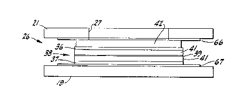
The tamper evident optically variable device 26 of a
type hereinafter described is disposed between the
flaps 19 and 21. An aperture window 27 is provided in
the outer flap 21 to permit viewing of the optically
variable device 26 to see whether or not it has angle
shifting properties. As can be seen from Figure 1, the
window 27 has a circular configuration. Other configu-
rations can be utilized if desired. For example as
shown in Figure 2, another type of window 31 has been
provided which has serrations 32 formed in its margins
which serve a purpose as hereinafter described.
The tamper evident optically variable device 26 of the
present invention can be of the type shown in Figure 3.
As shown therein, the tamper evident optically variable
device 26 can be of the type described in co-pending
application Serial No. 486,710 filed on July 12, 1985,
now Canadian Patent No. 1,253,367. As described
therein, it is comprised of at least first and second
layers 36 and 37 which form part of a metal-dielectric-
metal interference filter 38. A release layer 39 isdisposed between first and second layers 36 and 37 and,
as shown, is provided in a spacer layer 41. The layers
36, 37, 39 and 41 are formed upon and carried by a
substrate 42 to provide the interference filter 38.
The release layer 39 is disposed between the absorber
layer and the reflector layer. Three general designs
of the tamper evident optically variable device of the
present invention are ahown in Figures 5, 6 and 7.
Each of the deaigns consists of a substrate 56 which
has at least one aurface 57. The substrate 56 is
formed of a suitable material of the type described in
co-pending application Serial No. 486,710 filed on July
12, 1985, now Canadian Patent No. 1,253,367. As
described therein it can be formed of
A-43778/HCH
.. , ~ -~ , ~
S,
polyethylene terephthalate (PET). Typically the
substrate 56 can be formed of material having a thick-
ness ranging between 75 gauge and 140 gauge which would
be approximately .0075 inches to .005 inches. The
substrate material is preferably transparent. However,
if desired it can be opa~ue.
A reflector layer 58 is deposited on the curface 57 of
the substrate 56. The reflector layer 58 is formed of
a metal and is deposited to a thickness 60 that it is
opaque. The metal utilized should preferably be a high
reflector such as aluminum. Other metals can be
utilized which have a whitish appearance and which have
good reflection characteristics. For example, reflec-
tors such as nickel and silver (if stabilized) could be
used. In addition, other materials such as commonly
known grey metals can be utilized if their lower
reflection characteristics can be tolerated. The metal
utilized should be deposited to a thickness so it is
opaque. If aluminum is used, this would be a thickness
of approximately 600 Angstroms ~ 20~.
A dielectric spacer layer 59 is deposited on the metal
reflector layer 58. In order to obtain as rapid a
color shift as possible, it is desirable that the
spacer layer be formed of a material having a very low
index of refraction. For that reason, the layer is
formed of a dielectric having an index of refraction of
n c 1.65 or below. Materials meeting this criteria are
inorganic materials like magnesium fluoride, n ~ 1.38;
yttrium fluoride, n ~ 1.55; siliccn dioxide, n - 1.45,
etc. Organic materials such as TFE
(tetrafluoroethylene, Teflon~), n = 1.38; FEP
(fluorinated ethylene-propylene copolymer) n ~ 1.34;
polypropylene, n = 1.45; polyethylene, n = 1.5;
A-43778
7()6
polyethylene terephthate (PET, Mylar~) n = 1.6; or
waxes, n = (Fix) 1.5 may be utilized. The spacer layer
59 i5 put down to a thickness ranging from between 3
and 7 quarter waves with a design wavelength in the
visible spectrum that ranges from 400 to 700 microns.
It has been found that if more than 7 quarter waves are
utilized the color becomes muted or becomes white. If
approximately less than 3 quarterwaves are utilized,
there is insufficient color shift.
A metal absorber layer 61 is deposited on the spacer
layer 61. The thickness of the spacer layer 59 deter-
mines which wavelengths will be absorbed by the absorb-
er layer 61. Thus it can be seen that by changing a
thickness of the spacer layer, different colors can be
obtained for the color shift desired with the optically
variable device. The absorber layer 61 is formed of a
highly absorbing material such as a metal and is put on
to a thickness so that it provides substantially zero
reflection at the selected design wave length in the
visible spectrum. The metal which is utilized in the
absorber layer 61 can be any of the grey metals such as
chromium, nickel, titanium, vanadium, cobalt and
palladium. The use of such grey metals for the absorb-
er layer 61 is desirable because the gray metals have
high absorption values. A grey metal can be character-
ized as a metal having high absorption where the n & k
are nearly equal and the ratio of k over n is small as,
for example, in the range of 1:2. When the grey metal
is placed on the 6pacer layer to provide a minimum of
reflection in the visible spectrum, it has a thickness
which i8 in the vicinity of 100 Angstroms or less. For
example, if the absorber layer is formed of chromium,
it can have a thickness of approximately 65 Angstroms
10%.
A-43778
18~ O~
In the optically variable devices shown in Figures 4, 5
and 6, it can be seen that a metal dielectric metal or
tri-layer system design has been provided in which the
spacer layer serves the critical function providing the
desired color shift. In each o~ the three designs, a
release layer 62 has been incorporated, either in the
spacer layer 59 itself or on opposite sides of the
spacer layer 59. Thus as ~hown in Figure 4, the
release layer 62 has been provided between the absorber
layer 61 and the spacer layer 59. In the design shown
in Figure 5, the release layer 62 has been provid~d
between the spacer layer 59 and the reflector layer 58.
In the third design shown in Figure 6, the release
layer 62 has been provided between the two separate
portions of the spacer layer 59.
The release layer 62 is formed of a material having an
index of refraction which is close as possible to the
index of refraction of the spacer layer 59 so that it
does not effect to a significant degree the optical
propertie6 of the optically variable device. The
release layer 62 should be formed of a material which
permits separation of the metal-dielectric-metal
interference filter which comprises the optically
variable device. One material found to be particularly
satisfactory for this purpose i8 Teflon ~trademark)
which i- flashed onto the appropriate layer in the
desired po~ition as shown by any one of the three
designs ~hown in Figures 4, 5 and 6 to a suitable
thickness as for example, from 20 to 100 Angstroms. By
providing 6uch a release layer 62 it is possible to
readily separate the absorber layer from the reflector
layer and thus destroy the optically variable effects
of the optically variable device to render the optically
variable device non-functional. By separating the
absorber layer from
A-43778/HCH
`;'~'~
-
- 9 -
the reflector layer, the phase coherence of the inter-
ference filter is destroyed. Once this phase coherence
has been destroyed, it is impossible to re-establish
this phase coherence even if an attempt is made to
5 reassemble the two separated parts. It has been found
that once an optically variable device has been sepa-
rated in a manner in which the absorber layer is
separated from the reflector layer, the color shift
characteristics have been destroyed. Even if it would
be possible to restore some color shift characteris-
tics, a different color shift or color resembling an
oil slick would occur which would clearly disclose that
the optically variable device had been tampered with.
Attempts to re-establish the optically variable device
by gluing together the two parts would result in
failure because the glue itself would have some finite
thickness which would make it impossible to restore the
color shift characteristics so that a single color
would still remain or, at best, a different color shift
would be achieved.
The designs shown in Figures 4-6 can also be used in
the reverse configuration on the substrate 56. In this
instance, the color shift would be seen through the
substrate 56 and would by necessity be optically
transparent.
By way of example, optically variable devices incor-
porating the present invention with release layers
therein have been provided in which color shifts have
been achieved. One optically variable device had a
green color in reflectance when viewed at normal
incidence and at a viewing angle of approximately 45-,
it had a blue color. After it was pulled apart all
that could be seen on one side was an aluminum
A-43778
1~3~(~6
--10--
reflector and on the other side a greyish color in
transmission and at an angle only a tinge of blue in
reflection. Thus the optically variable device after
it once had been separated by the use of the release
layer and then placed together again would have a
silvery color at all angles, i.e., no color change with
angle, which would clearly indicate that the optically
variable device had been separated. In other words,
the optically variable device had its color shlft
capabilities destroyed clearly indicating tampering
with the optically variable device.
The optically variable device 26 can be any one of the
optically variable devices 51, 52 and 53 described in
Figures 4, 5 and 6. As shown in Figure 3, the optical-
ly variable device can be incorporated between the two
flaps 19 and 21 of the cardboard carton or container
11. Suitable means is provided for securing the
optically variable device to the flaps 19 and 21 and as
shown in Figure 3 can take the form of layers 66 and 67
of a suitable adhesive. The layer 66 secures the flap
21 to the substrate 42 and the adhesive layer 67
secures the flap 19 to the layer 37. After the opti-
cally variable device has been glued between the two
flaps 19 and 21 by the use of the adhesive layers 66
and 67 and is positioned in such a manner so that it is
visible through the opening 27, a color shift with
angle can be ascertained. By way of example, at normal
incidence, the optically variable device will have a
green appearance and at an angle of approximately 45-,
the optically variable device will have the color of
blue.
When the outside flap 21 is opened, the optically
variable device 26 will be separated at the release
A-43778
706
--11--
layer 39. As soon as the optically variable device has
been separated, the angle shifting properties are
destroyed. Thus it can be seen that if such an opti-
cally variable device were to be utilized on a package
for a consumer type product, the consumer picking up
the product from a store shelf could readily ascertain
whether or not there had been any tampering with the
product by viewing the optically variable device to
ascertain whether or not a color shift occurs with
change of viewing angle. If there is no color shift,
then the consumer knows that the product has been
tampered with and should not be purchased.
In the embodiment shown in Figure 3 it can be seen that
the reflector can be deposited on the substrate fol-
lowed by the spacer layer and the absorber layer. In
certain applications, it may be desirable to reverse
this se~uence by depositing the absorber layer on the
substrate followed by the spacer layer and then depos-
iting the reflector layer. When manufactured in this
manner, the optically variable device can be mounted in
the manner shown in Figure 3 in which the substrate 42
faces the opening making it necessary to view the
optically variable device through the polyester film
which is utilized for the substrate. Such an arrange-
ment is desirable because the polyester film inhibits
cutting through the optically variable device and
removing a portion of the optically variable device.
Such cutting operations can be inhibited by the use of
serrations 32 as shown in Figure 2. By providing such
serrations, it would be very difficult, if not impossi-
ble, to remove a portion of the optically variable
device and affix it to another carton already tampered
with without destroying the same. It should be appre-
ciated that if desired, the optically variable device
A-43778
1~3~
-12-
can be positioned in such a manner so that the sub-
strate is positioned away from the opening 27.
Another embodiment of the invention is shown in which
the tamper evident optically variable device i6 incor-
porated into the bottle itself rather than into the
package containing the bottle. This embodiment is
shown in Figures 7, 8 and 9. As shown therein, the
bottle 13 is provided with a necked portion 13a which
is provided with external threads 68 which are adapted
to receive the cap 14 which encloses the opening 69 in
the neck 13a. An optically variable device 26 of the
type hereinbefore described is sized to fit over the
top of the necked portion 13a and has one side of the
same, as for example, the substrate side secured to the
top of the necked portion 13a by suitable means such as
an adhesive layer 71. After the optically variable
device 26 has been applied to the top of the bottle 13,
a clear adhesive 72 is applied to the top of the
optically variable device 26 as shown in Figure 7 and
thereafter the cap 14 is screwed onto the necked
portion 13a of the bottle 13 to spread out the glue 72
to form an adhesive layer 73 between the cap and the
optically variable device 26. The cap 14 as shown is
transparent 50 that the optically variable device 26
can be viewed through the adhesive and top of the cap.
It should be appreciated, if desired, a portion of the
cap can be formed so it is opaque with only a portion
of the same being transparent so as to permit viewing
of the optically variable device 26.
When the bottle 13 is opened by rotating the cap 14,
the optically variable device 26 is destroyed because
the adhesive layers 71 and 73 hold the optical device
26 to the top of the neck of the bottle 13a and the
A-43778
bottom inside of the cap 14 60 that rotation of the cap
14 causes a shearing action to take place within the
optically variable device 26 along the plane of the
release layer provided within the spacer layer 41 to
cause the optically variable device to separate as
shown in Figure 9 and to cause destruction of the angle
shifting characteristics of the optically variable
device. Thus again it can be seen that if the bottle
has been tampered with, the optically variable device
will be destroyed which will give a visible indication
to the consumer that tampering has occurred because the
angle shift properties causing the changes in color
with viewing angle will no longer be present.
Another embodiment of consumer type packaging is shown
in Figure lO and consists of a rectangular cardboard
container or package 76 which can be rectangular in
cross section and which is provided with an opening 77
in its top side through which the necked portion 13a of
the bottle 13 can extend. The bottle is provided with
a transparent cap 14 of the type hereinbefore described
through which the optically variable device 26 posi-
tioned therein can be viewed. A shrink wrap 81 of a
conventional type also formed of a transparent plastic
can be applied to the top of the bottle and to the top
of the container 76 to facilitate handling of the
package. In such an embodiment it is still possible to
view the optically variable 26 through the transparent
wrap 81 and also through the transparent cover 14 to
see whether or not tampering has occurred with respect
to the bottle 13 by viewing the optically variable
device 26 to see whether the angle shift properties are
present.
A-43778
1~3 ~)6
From the foregoing it can be seen that there has been
provided a tamper evident optically variable device
which can be utilized in connection with various types
of articles such as containers for packaging various
products and particularly consumer type products. The
optically variable device can also be used on customs
seals, ~lassified document seals and the like. The
tamper evident optically variable device can be readily
incorporated into conventional type packaging utilized
on consumer products. The tamper evident optically
variable device has such characteristics that the
public can be readily educated to ascertain whether or
not tampering has occurred with respect to the contain-
er or package carrying the product. The consumer at
the point of sale can readily ascertain whether tamper-
ing has occurred by viewing the optically variable
device. If the optically variable device is without
color shift properties when viewed at different angles,
the consumer will know that tampering has occurred and
can bring this to the attention of the retailer dis-
tributing the product.
A-43778