Note: Descriptions are shown in the official language in which they were submitted.
3~
-- 1 --
DEVICE FOR RAISING AND LOWERING LOADS
BACKGROUND OF THE INVENTION
This invention relates to devices for raising
and lowering loads; particularly devices used by skyscraper
workers, construction workers, and rescue personnel to
raise and lower equipment or people.
A typical device uses a rope with one end
connected to the load and the other end connected to a
man, who exerts the force necessary to raise and lower
the load. As the rope is pulled by the man, the load
is raised. Release of the rope by the man causes the
load to be lowered. If the man merely holds onto the
rope, then the load is neither raised nor lowered, but
is held stationary at a constan-t heicJht. As a safety
feature, a typical device has a brake that restrains
the rope in one direction. One type of brake uses a
stationary clamp to llold the rope between the clamp and
a pulley. The clamp has teeth and thus prevents -the
rope from moviny in one direction.
A typical braking system is activated in two
ways. First, the brakincJ system is periodically acti-
vated as the rope is pulled by the man. In this way
the man can stop pulling at selected points and the
rope will be locked in one direction. Second, t~e
bra}cing system is activated if the load is lowered at a
rate above a se].ected threshold. In this way, if the
-- 1 --
~3~
man releases the rope at a point where the brake is not
enc~acJed, then the brakil1cJ system will stop the load
from fallinc~ once the load has reached a selected speed.
A t~pical raisincJ and lowerincJ device uses
several pulieys to reduce tile amount of force re~uired
to ~aise tlle load. A~ least one of the additional pulleys
is a one-way pulley whicll rotates i.n one direction only.
By usin~ a one-way pulley, the advantages of a block
and tackle arran~ement are achieved when the load is
raised, and when tlle load is lowered, a frictional force
is produced because the one-way pulley cannot turn.
Therefore, the rope slides over the pulley's surface
creating friction. This allows the load to be lowered
at a steady rate.
SUMMARY OF THE INVENTION
The present invention is directed to a device
for raising and loweriny a load in which a braking
device, a braking device indicator and a one way pulley
are used.
Generally, the present invention relates to a
device for raising and lowering a load having a braking
means for braking the device. In addition, the device
includes an indicator flag which indicates when the
braking means is enabled. The device also includes a
pulley which only rotates when the load is advanced in
a selected direction.
There is provided according to the invenkion a
device for raising and lowering a load, comprising:
a cord adapted to be connected to means for
raising the load and adapted to be connected to the
load,
a housing,
a pulley rotatably mounted on the housing and
~ .
-- 2 --
.~ .
12~3~
- 2a -
having a cord-receiving surface, the cord being
trained over the cord-receiving surface and movable in
a load-lowering direction and in a load-raising
direation,
braking means on the housing, adjacent the cord,
and intermittently enabled by the rotation of the
pulley as the load is being raised for preventing
movement of the cord in the load-lowering direction,
means for intermittently enabling the braking
means in response to rotation of the pulley, and
displaying means movably mounted on the housing
and responsive to the braking means being enabled for
visually displaying when the braking means is enabled.
According to another aspect of the invention,
there is provided a device for raising and lowering a
load, comprising:
a cord adapted to be connected to the load and
to means for raising the load,
a housing having a braking surface ad~acent the
cord,
a pulley rotatably mounted on the housing and
having a cord-receiving surface, the cord being
trained over the cord-receiving sur~ace and movable in
a load-lowering direction and in a load-raising
direction, and
braking means on the housing, adjacent the cord,
for preventing movement o~ the cord in the load-
lowering direction, the braking means including,
a cam rotatably mounted on the housing, and
having an enlarged radius portion,
a cam ~ollower movably mounted on the housing
and engageable by the enlarged radius portion,
a braking elemenk ad-jacent the cord on a side
opposite the housing braking sur~ace,
- 2a -
3~2~fi~
- 2b -
means for rotatiny the cam with the pulley when
the pulley rotates in the load-raising direct.ion, and
for permitting the cam to remain stationary when the
pulley rotates in the load-lowering direction, and
linkage means connecting the braking element to
the cam ~ollower for posit.ioning the braking element
when the cam follower is engaged by the enlarged
radius portion so that the cord, when moved in the
load-lowering direction, is wedged between the braking
element and the braking surface.
According to a further aspect of the invention,
there is provided a one-way p~lley, comprising:
a hanger plate,
a pulley cylinder rotatably mounted on the
hanger plate, and having a cord-receiving surface, and
a bore which defines a radially inward braking surface
opposite the cord-receiving surface,
a stop pin fixed on the hanger plate, located
within the pulley bure, and spaced from the braking
surface,
a braking element having a narrow end narrower
than the space between the braking surface and the
stop pin, and a wider snd wider than the space between
the braking surface and the stop pin,
means locating the braking element within the
pulley bore, and between the braking surface and the
stop pin, and
means for wedging the braking element wider end
between the braking surface and the pin when the
pulley cylinder is rotated in one direction, and for
forcing the braking element to retract slightly from
between the braking surface and the pin to allow free
rotation of the pulley cylinder when the pulley
cylinder is rotated in an opposite direction.
~,~
- 2b -
~Z~39~
- 2c -
BRIEF DESCRIPTION OF THE DRAWING5
FIGURE 1 is an elevation view of a preferred
embodiment of the invention attached to a load.
FIGURE 2 is an elevation view of the preferred
embodiment of the invention.
FIGURE 3 is a cross-sectional view taken along
line 3 - 3 of FIG. 2.
_ _ /
- 2c -
`` ~2~39~
-- 3
FIGURE a, is an explocled perspective view of a
cam and a pulley of the embodiment of FIG. 2.
L IGURE 5 is a sectional view taken along line
5 - 5 of FIG. 3 showincJ a brakincJ system of the pre-
5 ferred embodiment when it is clisabled.
FIGURE 6 is a sec-tional view taken along line
5 - 5 of FIG. 3 showing a bralcing system of the pre-
ferred embodiment when it is enabled.
FIGURE 7 is a sectional view taken along line
10 5 - S of FIG. 3 showing the operation of a braking
system when a load is lowered at a speed above a
selected threshold.
FIGURE 8 is a detailed representation of a
one-way pulley of the preferred embodiment.
FIGURE 9 is a cross-sectional view taken along
line 9 - 9 of FIG. 8.
FIGURE 10 i s an elevation view of a brake
indicator system of the preferred embodiment showing a
brake indicator flay in a position indicating that the
20 braking system i s di sabled .
FIGURE ll is an elevation view of a brake
indicat~or system of the preferred embodiment showing a
brake indicator flag in a position indicating that the
brakiny system is enabled.
25 DETAILED DESCRIPTION OF THE
PRESENTLY PREFERRED EMBODIMENTS
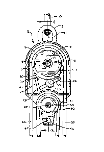
Referring now to the drawings, FIGS. 2 and 3
show a preferred embodiment o the invention. A raising
and lowering device is yenerally shown at 2. The device
30 inclucles a housiny ~, a main pulley 6, a cam 16, a cam
follower 20, a brakincJ element 30, and a one-way pulley
~0 . The housing a~ i s preferably made of aluminum and
defines a brakiny surface 5. Inteyrally attached to
the housing aS is a rnountincJ extension 3 which defines
- 3 -
3~9
-- 4
an aperture 11. A mounting clevice 15, SUCIl as a hook
Ol a rope, enyages the mounting extension 3, -tllroucJh
the aperture 11. In this manner the raisinCJ and lower-
ing device may be mounted in a variety of locations.
The main pulley 6 is preferably made of
aluminum and is rotatably attached to the housing 4 by
a main pulley shaft 8 and a plain bearing 21 which pass
through aperture 7. As best seen in FIG. 4, the main
pulley 6 has a bore 10. Rotatably attached to the main
pulley 6, within the bore 10, are overspeed pawls 12
and a ratchet pawl 14. Preferably, the overspeed pawls
12 and the ratchet pawl 14 are made of bronze. As best
seen in FIG. 5, torsion wire springs 9 bias the overspeed
pawls 12 radially inward, toward the center of the main
pulley 6. Torsion wire spriny 13 biases the ratchet
pawl 14 radially outward toward the inner surface of
the bore 10. A cam 16 having extensions 18 is positioned
around the main pulley shaft 8 by means of an aperture
19 so that the extensions 18 extend into the bore 10.
20 As best seen in FIGS. 10 and 11, the cam 16 has a rib
17. Preferably the cam 16, the extensions 18 and the
rib 17 are forged as a sinc;le unit and are made of steel.
As best seen in FIGS. 5, 6, and 7, a cam
follower 20 is rotatably attached to a pivot arm 22
which is rotatably attached to the housinc3 4 by a pivot
shaft 2~. Preferably the cam follower 20 is circular
and is made of brass. A torsion wire sprincJ 23 biases
the pivot arm 22 toward the main pulley 6. A pivot arm
extension 26 is rotatably at-tached to the pivo-t arm 22
by a pivot shaft 28. A bra]cing element 30, preferably
wedge-shaped, is attached to the pivot arm extension 26.
Preferably, the pivot arm 2%, the pivot arm extension 26,
and the brakiny element 30 are made of steel and the
~39~
- 5 ~
brakiny element 30 is attached to the pivot arm eY~ten-
sion 26 by a screw 31. A -torsion wire spring 29 biases
the pivot arm extension 26 toward the main pulley 6.
As bes-t seen in EIGS. 10 and 11, a brake
lndicator 32, preferably made of aluminum, is rotatably
attached to the housincJ 4 about a boss 34. The boss 34
is intec~ral with the housing 4 ancl receives the pivot
shaft 24. The brake indicator 32 has a colored flag
region 36, a non-colored region 37 and a lever 33. The
housing 4 has a flag window 38 which exposes a portion
of the brake indicator 32. An extension spring 35
biases the brake indicator 32 in a counterclockwise
direction 39.
~ As shown in FIGS. 8 and 9, a one-way pulley
40 is attached to the housing 4 by a one-way pulley
shaft 42 and a plain beariny 48. The one-way pulley 40
is preferably made of aluminum and has a bore 44 which
defines a braking surface 49. The brakiny surface 49
includes a plurality of ratchet teeth 43. A hanger
plate 46 is fixedly re-tained adjacent to the one-way
pulley 40, around the one-way pulley shaft 42. Pre-
ferably, bosses, not shown, on the housing 4 are
located on either side of the hanger plate 46 to hold
the hanger plate 46 in a fixed position. The hancJer
plate 46 has an aperture 47 for receiving a hook or
riny, such as a carabiner, not shown. A hanc3er stop
pin 50 is welded to the hancJer plate 46, and eY~tends
into the bore 44. A brakillcJ element 51, preferably
sickle-shaped, is also located in the bore 44. A
torsion spring 45 biases the braking element 51 toward
a position between the hancJer stop pin 50 and the
braking surface 49. Preferably, -the hanger plate 46,
the hanger stop pin 50, and the bralciny element 51 are
made of stainless steel.
A cord 52, which is preferably KMIII static
Kernmantle rope made by New Enyland ~opes of New
- 6 _ ~ ~3~~
Bedford, Massachuset-ts, but may be a cable or another
similar object made of flexible ma-teria]., is received
by the housiny 4, around the main pulley 6. A load 54
is connec-ted to one encl of the cord 52. The load may
be an animate or an inanimate objec-t, including a
person, a rescue chair, a safe, or a crate. Tl1e other
end of the cord is connected to a pullincJ device 56,
preferably a man.
Figure 1 shows the preferred embodiment of
the invention attached to a load 54. An auxiliary
pulley 58 is contained within an auxiliary pulley
housiny 60. The auxiliary pulley housincJ 60 is
attached to the load 54. The cord 52 is fixedly
attached to the auxiliary pulley housiny 60 and engages
the one-way pulley 40, and the auxiliary pulley 55 be-
fore enyaging the main pulley 6. Preferably, the pull-
iny device 56 always acts on the part 66 of the cord 52
that extends from the the housing 4 where the braking
element 30 is located.
As shown in FIG. 6, as the pullinc3 device 56
pulls on the cord 52 in a downward direction 53, the
load 54 is raised in an upward direction 55. While the
pulling device 56 is pulliny on the cord 52, the main
pulley 6 rotates in a coun-terclockwise direction 57
about the main pulley shaft 8. As the main pulley 6
rotates in this manner the ratche-t pawl 14 enyac~es one
of the extensions 18 and forces the cam 16 to rotate
with the main pulley 6. As the cam 16 rotates, it
intermittently enyages the cam follower 20. As best
shown in ~IG. 5, when encJacJed by the cam 16, the cam
follower 20 forces the pivot arm 22 and the pivot arm
extension 26 to rotate in a counterclockwise direction
57 about the pivot shaft 24. This movement of the
pivot arm extension 26 coupled with the force due to
the wire torsion sprin~ 29 pulls the brakilly element 30
out of a brakiny position. Therefore, when the cam 16
-- 6 --
~3~
-- 7
is encJaging the cam follower 20, the braking system,
also referred to as -the cord restraininc~ system, is
disabled.
As best seen in FIGS. 10 and 11, as the cam
16 rotates in a counterclockwise direction 57, the cam
rib 17 inter;nittently engaCJes the brake indicator lever
33. The brake indica-tor lever 33 is engaged a-t approx-
imately the same time that the cam follower 20 is engaged.
As the cam rib 17 engages tlle lever 33, the brake indica-tor
32 is rotated in a clockwise direction 27 about the
boss 34. As the brake indicator 32 is rotated, the
brightly colored flag region 36 is positioned so that
it is visible througll tl~e flag window 38. Therefore,
when the braking system is disabled, the colored flag
region 36 is visible through the flag window 38. By
reversing the regions 36,37, the colored flag region 36
will be visible when the brakinc3 system is enabled.
Thus the brake indicator 32 indicates the operational
status of tlle braking system.
As best seen in FIG. 6, when the braking
element 30 is in the braking position, the braking
system is enabled and the cord 52 is prevented from
advancing in a direction 68 that would lower the load
54. When the braking element 30 is in the braking
position, and the cord 52 is released, the braking
element 30 is forced between the cord 52 and the main
pulley 6 by the frictional force of the cord 52 against
the brakiny element 30 and the force of the torsion
spring 23. As the brakincJ element 30 is forced between
the cord 52 and the main pulley 6, the cord 52 is forced
acJainst the brakiny surface 5. This force is sufficient
to hold the cord 52 so that it cannot advance in the
load-lowering direction 68, thus braking the cord 52.
As best seen in FIG. 5, if the brakiny ele-
ment 30 is not in -the brakiny position because the cam
16 has engayed the cam follower 20, then the load 54
- 7 -
~3 ~Z~3~
may be aclvanced in the load-lowering direct.ion ~8. As
the load 54 is lowered, the cord 52 enyages the main
pulley 6, causing i-t to rotate in a counterclockwise
direction 57. As the main pulley 6 rotates the cam 16
remains stationary due to the frictional force created
between the cam 16 ancl the cam follower 20 and between
the cam 16 and the main pulley shaft 8. Due to the
shape of the ratchet pawl 14 and the force of the
torsion wire spring 13, the ratchet pawl 14 does not
engage the extensions 18. Instead, the cam extensions
18 displace the ratchet pawl 14 as it is rotated by the
main pulley 6. Therefore, the braking system remains
disabled as the load 54 is lowered.
As best seen in FIG. 7, if the load 54 is
lowered or the pulliny device 56 completely releases
the cord 52, causing the load 54 to drop rapidly, then
the main pulley 6 rotates in a clockwise direction 59.
If the load 54 drops at a rate above a selected speed,
preferably 3 feet/sec., then the main pulley 6 will
rotate above a selected speed, preferably 450 rpm, thus
producing a centrifugal force yreat enough to overcome
the biasing force of the springs 9 attached to the over-
speed pawls 12. This centrifugal force causes the over-
speed pawls 12 to extend outward and engage at least
one of the extensions 18. Once an extension 18 is
engaged by an overspeed pawl 12, the cam rotates with
the main pulley 6 and disenc3ages the cam follower 20,
thus bringinc~ the bra)ciny element 30 back into the
braking position. This action stops the movement o~
the cord 52 in the load-lowering direction 68 and thus
stops the lowering of the load 54. This type of over-
speed pro-tection device is well-known to those skilled
in the art.
Turniny now to the operation of the one-way
pulley 40, as best shown by reference to FIGS. 8 and 9,
- 3 2~3~~
g
when the one-way pulley 40 attempts to turn in the clock-
wlse direction 62, the brakiny element Sl is forced
between the hancJer stop pin 50 and the braking surface
49 of the one-way pulley 40 by one of the ratchet
teeth 43 and by the force of the spring 45. When the
one-way pulley 40 turlls ln -the counterclockwise direction
64, the friction from the bra]~ing surface 49 forces the
braking element 51 to retract slightly from between the
hanger stop pin 50 and the brakinc3 surface 49. This
allows the one-way pulley 40 to freely rotate in the
counterclockwise direction 64.
The one-way pulley 40 may be used to reduce
the difficulty encountered when the load 54 is lowered
by a man. The one-way pulley is positioned as shown in
FIG. 1 so that it only rotates in a counterclockwise
direction 64. When the load 54 is raised, the one-way
pulley 40 rotates freely and reduces the force neces-
sary to raise the load 54. When the load 54 is lowered,
the one-way pulley does not rotate and a frictional
force is created as the cord 52 slides over the one-way
pulley 40. This frictional force reduces the upward
force experienced at the rope side 66 and makes it
easier for the pull.ing device 56 (in this case a man)
to ease the load 54 down gently at a constant ra-te.
Of course, it should be understoocl that
various chancJes and modifications to the preferred em-
bodiment described herein will be apparent to those
skilled in the art. It is therefore intended that the
foregoincJ detailed description be regarded as illus-
trative rather than limiting, and that it be understood
that ik is the following claims, includiny all e~uiva-
lents, which are intended to define the scope of this
invention.