Note: Descriptions are shown in the official language in which they were submitted.
~ 3~
A COOKING APPLIANCE WITH ELECTRIC HEATING
BACKGROUND OF THE INVENTION
Field of the Invention
The present invention relates to a cooking
appliance provided with a plastic skir-t, a metal pan
and an electric heating resistor.
The invention applies in particular to deep
fryers.
Description of the Prior Art
In the majority of known electric fryers, the
pan of metal such as aluminum is directly exposed to
the surrounding air, which is attended by the following
disadvantages :
- at the time of operation of the fryer, the pan easily
attains a temperature equal to 150C, with the result
that users are liable to burn themselves in contact
with said pan,
- in view of the fact that the pan is directly exposed
to the surrounding air, heat losses are substantial,
which i5 detrimental to thermal ef~icienc~ and con-
sequently increases power consumption,
- the bare metal o~ the pan i~ not conducive to a
particularly attractive appearance.
A Eew attempts have been made to overcome the
disadvantages mentioned above.
In order to improve the appearance of the
appliance and to reduce th~ external temperature t con-
sideration has already been given to the possibility
of surrounding the pan with an enameled metal skirt.
A further attempt has consisted in surround-
-
ing the pan with a plastic skirt. However/ the attach~
ment of the metal pan within the plastic skirt is such
that numerous thermal bridges exist between said pan
and said skirt. By reason of these numerous khermal
20155-45~
bridges, the sklrt is necessa:rily formed of plastlc mate:rial which
is capable of contj.nuously withstanding ternperatures highe:r than
150C, such as the polyamides and the polyesters. These p].astics
have the major disadvantage of being ~ery costly, with the result
that they are incompatible with large-scale manufacture of low-
priced fryers.
The object o:E the present invention is to produce a
cooking appliance such as a low~priced deep Eryer while
effectively guarding users against any danger of burning and at
the same time preventing heat losses to the exterior~
SUMMARY OF THE INVENTION
In accordance with the invention, the cooking appLiance
comprising a metal pan and an electric heating resistor, said pan
being surrounded by a plastlc skirt, is distinguished by -the fact
that said skirt is of plas-tic material which does not continuously
withstand the temperature of the pan wall. Said sklrt entirely
surrounds the lateral wall and khe base of the pan ancl is
separated from these latter by an ai.r ~pace oE suE~icient width t(>
lim:it the l:emperature of the ski.rt to a va:Lue whic~ L.~3 compat:ibl(3
~0 w:lth the thermal resL.st:ance of the plasti.c material oE the skirt.
Sai.d skirt ls completely free with respect to the pan, with the
exception of a ring which joins the top edge of the skirt to the
top edge of the pan, said ring being of heat-insulating material
which is continuously resistant to the temperature of the top edge
of the pan.
This invention also provides an electrical deep Er~er
comprising a metal pan having a waLl, and an electric heating
,. ~
~, , r",~
~3~
20l55-455
resistor that heats .said wa:ll direc-tly by conductive heating to a
temperature higher than 150C, sald pan being surrounded by a
plastic skirt, wherein said skirt is of plasti.c material which
does not continuously withstand a temperature of 150C, said skirt
entirely surrounding the lateral wall and the base of -the pan and
being separated Erom said wall and said base by an air space of
sufficient width to limit the temperature of the skirt to a value
which is compatible with the thermal resistance of the plastic
material of the skirt, said skirt being completely free with
respect to the pan wi-th the exception of a ring which joins only
the top edge of the skirt to the top edge of the pan, said ring
being of heat-insulating material which is continuously resistant
to the temperature of the top edge of the pan.
Thus the pan is attached to the interior of the skirt in
such a manner as to ensure that the only contact between said
skirt and said pan is located at the level of the ringO However,
by reason of the fact that the ring is of heat-resistant
in.sulating material,
- 2a -
" ~
the skirt is not liab]e to be heated to an excessive
temperature.
Thus the skirt can be formed of lower grade
plastic material such as polypropylene which does not
continuously withstand a temperature higher than 80C.
In view of the fact that only the ring is of
noble material, the cooking appliance equipped with its
outer skirt is inexpensive to produce,
Moreover, by virtue of the substantial air
space located between the pan and the plastic skirt,
loss of heat to the exterior is very low, thus making
the cooking appliance particularly economical to,use,
In addition, users are not liable to burn them-
selves when touching the appliance since the temperature
of the skirt does not attain an excessive value. Thus
the fryer can be touched at any time, either in order to
move it during operation or immediately after the heak-
ing has been switched-of~.
Moreover, the plastic skirt can be molded in
any desired shape which is pleasing to khe eye, thus
making the appliance particularly attractive.
In an advantageous embodiment of the in~ention,
the lid of khe appliance is formed by a metal plate which
is intended to cover the top edge oE the pan in a sub-
stantially fluid-tight manner, the plate being covered b,y
a lid of plastic material o~ the ~ame nature as t,hat of
the skirk, said lid being separated rom the metal plate
by an air space, the conneckions bekween said plake and
said lid being locaked solely ak different points.
Thus the lid ikself is maintained at a low
temperature and is not liable to burn the user. Both
the lid and the skirt can be made of inexpensive plaskic
material, ~
In a preferred embodiment of khe invention,
the ring of heat-insulating makerial is provided with an
.
annular groove in the edge adjacent to the top edge o
the plastic skirt. Said annular groove is engaged on
the top edge of the skirt, the top edge of the pan being
provided with an annular flange which is bent back so as
to define a downwardly open channel which is engaged on
the adjacent edge of the ring.
Thus the pan is suspended from said ring which
is in turn engaged on the top edge of the skirt, thus
ensuring that the pan is reliably attached within the
skirt without any thermal bridge other than the very
narrow contacts between the edges o~ the pan, of the
ring and of the skirtO
BRIEF DESCRIP~ION OF THE DRAWINGS
FIG. 1 is a longitudinal sectional view of a
deep fryer in accordance with the invention.
FIG. 2 is a view to a larger scale showing the
detail A of FIG. 1.
FIG. 3 is a view in elevation of the fryer.
FIG. 4 is a plan view of a holder for handling
the frying basket o the fryer~
DETAILED DESCRIPTION OE' THE INVENTION
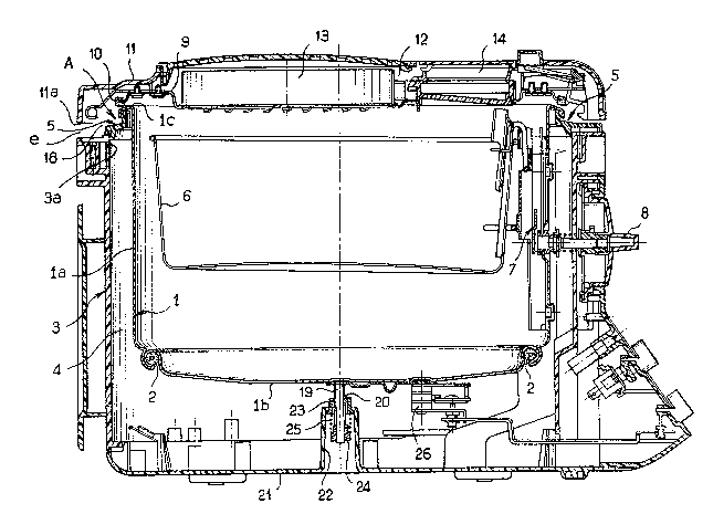
In the embodiment of FIG. 1, the deep fryer
essentially comprises an oil pan 1 of metal and an
electric heating resistor ~. Said pan 1 is surrounded
by a skirt 3 of plastic material such as polypropylene
which does not continuously withstand the temperature of
the wall of the pan 1.
Within the pan 1 is housed a frying basket 6
which can be lifted or lowered by means of a device 7
operated from the exterior by a rotatable knob 8 (as also
shown in FIG. 3).
The skirt 3 completely surrounds the lateral
wall la and the base lb of the pan 1 and is separated
from these latter by an air space 4 of suf~icient width
to limit the temperature of the skirt 3 to a value (for
~3~
example less than 80C) which is compatible with the
thermal resistance of the plastic material o~ the skirt
3. Moreover, said skirt 3 is completely free with
respect to the pan 1 except for a ring 5 which joins the
top edge 3a of the skirt 3 to the top edge lc of the pan
and from which this latter is suspended. Said ring 5 is
of heat-insulating material which is continuously
resistant to the temperature of the top edge lc of the
pan 1. By way of example, said ring 5 can be of poly-
amide or of polyester.
The lid of the fryer is formed by a disk-
shaped metal plate 9 which covers the top ed~e lc of the
pan 1 in a substantially fluid-tight manner by means of
an annular seal 10. Said plate 9 is covered by a lid ll
of plastic material of the same nature as that of the
skirt 3. Said lid 11 is separated from the metal plate
9 by an air space 12. The connections between said
plate 9 and the lid 11 are solely at cli~ferent points.
Between the metal plate 9 and the lid 11 is
disposed a deodorizing filter 13. In proximity to this
filter 13 is located an inspection window 14 for super-
vision of the frying operation.
In the embodiment shown in the drawings, khe
ring 5 o~ heat-insulating material i. providecl (as ~hown
in FIG. 2) with An annular groove 15 in that ~dge 5a of
said ring which i6 adjacent to the top edge 3a of the
plastic skirt 3, said annular groove 15 being engaged
on the top edge 3a of the skirt 3.
Moreover, the top edge lc of the pan is pro~
vided with an annular flange 16 which is bent back so
as to define a downwardIy-open channel 17, said channel
being engaged on the adjacent edge 5b of the ring 5.
In the example illustrated, the ring 5 has a
substantially L shaped transverse cross~ ection, one
portion 5c of the L being substantially parallel to the
--6--
lateral wall la of the pan 1 and located in spaced
relation to this latter wh.ilst the other port:ion 5d
extends radially towards the plastic skirt 3.
Furthermore, when the lid 11 is closed, the
bottom edge lla of this latker is separated from the top
edge 3a of the skirt 3 by a gap e of sufficient width to
allow the annular space 18 surrounding the ring 5 to
communicate with the external air. Thus the ring 5 is
cooled by the surrounding air and is not liable to be
heated to an excessive temperature.
The base lb of the pan 1 has a vertical rod 19
engaged in an opening 20 which is formed in a re~cess 22
of the base 21 o~ the outer skirt. Said opening 20 is
separated from the rod 19 by a sleeve 23 of hea-t-
insulating and heat-resistant material sllch as polyamide.
The end of said rod 19 is fitted wlth a nut 24 or the
like which is held tightly against a spring 25, said
spring being applied against the edge of the opening 20
which is remote from the pan 1. This arrangement serves
to compensate for manufacturing tolerances as well as
dimensional variations caused by heat expansion.
It is also apparent from FIG~ 1 that the
electric heating resistor 2 is crimped wikhin the base
lb of the pan l and .is sufficiently remote ~xom the base
21 and from the lateral wall of the sk:irt 3 to prevent
any excessive heating of this latter.
A thermostat 26 is attached to the base lb of
the pan 1 and iæ in turn remote from the base 21 o~ the
skirt 3 of plastic material in order to prevent any
thermal bridge which would be liable to heat this
plastic material to an excessive extent.
The deep fryer in accordance with the
invention is provided with a holder 27 for handling -the
frying basket 6 (as shown in FI~. 41. Said holder 27
has a handle 28 at the end of which is fixed an arm 29
fitted with a hook 30.
As shown in FIG. 3, the skirt 3 is provided on
its lateral face with a vertical slot 31 in which the
basket holder 27 is flush-mounted in a detachable manner~
This arrangement is made possible by the relatively sub-
stantial distance (3 to 5 cm~ between the pan 1 and tha
zone of junction of the cylindrical portion of the skirt
3 with the flat portion 32 which surrounds the control
knob 8.
The main advankages of the fryer described in
the foregoing are as follows :
The outer skirt 3 of plastic material sePar-
ated from the oil pan 1 makes it possible to isolate
this latter and to guard the user against any danger of
burning. At the same ti~e, the air space 4 which sur-
rounds the pan 1 considerably limits heat losses to the
exterior, thus permitting a reduction in power consump-
tion.
Moreover, in addition to the fact that the
skirt 3 is practically free with respect to the pan 1 or
in other words that no thermal bridge is created between
the pan and the skirt, this latter can be fabricated
from inexpensive oxdinary-gxade plastic material which
does not afford resistance to high temperatures, thu~
permitting low-cost produation o~ the ~,ryer.
The onl~ portion of the fryer which involves
relatively high capital expenditure is the ring 5 which
must be of noble material having good high-temperature
strength. However, the incidence of said ring on the
cost of the fryer i5 low, taking into account the small
dimensions of this part.
The merit of the present invention lies in
particular in the fact that, by virtue of a ring of
simple design, there has been found an efective, solu
tlon to the problem presented. This ring alone carries
~3~
out all the Eollowing functions :
- it defines the spacing between the pan 1 and the
external plastic skirt 3,
- it serves to support and to center the pan 1 within
the skirt 3,
- it completely closes off the air space between the
pan 1 and the skirt 3,
- it permits free expansion of the pan 1 with respect
to the skirt 3,
- it has the effect of limiting heat ~ransfer between
the pan 1 and the skirt 3.
Moreover, the outer skirt 3 of molded plastic
material as well as the lid 11 formed of the same
material gives the fryer an entirely new and attractive
appearance. This appearance is due in particular to the
fact that the control elements of the fryer as well as
the basket holder 27 are remarkably integrated in the
skirt as shown in FIG. 3.
As will be readily apparent, the invention is
not limited to the example of construction described in
the foregoing and any number o~ modifications may
accordingly be contemplated without there~y departing
from the scope or the spirit of the :Lnvention.
Thus the skirt, the lid 11 and the ring 5 can
be made o plastic material~ other than those yiven by
way of example in the foregoing descriptLon.
The invention is applicable to cooking ~
appliances other than deep fryers, such as pressure
cookers with integrated electric heating, slow cookers,
rice cookers, steam cookers and the like.
.