Note: Descriptions are shown in the official language in which they were submitted.
S P E C I F I C A T I O N
T I T L E
"TRANSVERSE ZIPPER BAG MATERIAL AND
METHOD OF AND MEANS FOR MAKING SAME"
BACKGROUND OF THE INVENTION
The present invention relates to improvements in
mechanisms and methods for the manufacture of reclosable plastic
bags and more particularly to an improved arrangement wherein a
continuous sheet of film is prepared by attaching fastener
elements to the surface thereof~
In the manufacture of plastic bags, various approaches
have been used, some where the fastener profiles are integral
with extruded thin plastic film material and others wherein the
plastic profile strips are attached to the surface of the film.
In most arrangements, the bags essentially are formed in side-to-
side relationship with the fastener profiles extending parallel
to the contlnuous strip of material. When this type of material
is converted into bags on certain form, fill and seal machines,
the fasteners will end on the wrong part of the bag, i.e., along
the side instead of across the top. In order to provide a bag
made in such an form, fill and seal machine, with the fastener
across the top, it is necessary to position said fastener across
the machine direction of the film.
.
---- /
~2~473
Other procedures less frequently used have provided bags
in end-to-end`relationship whereby the continuous material can be
rolled on a roll with the material of uniform thickness in the
axial direction of the roll.
An object of the present invention is to provide an
improved method and apparatus for the manufacture of material
from which plastic bags are to be made employing a unique
arrangement for the attàchment of the fastener members with the
members extending laterally across a continuous supply of bag
material to provide material suitable for use in a form, fill and
seal operation.
A further object of the invention is to provide an
arrangement wherein separate and different coacting fastener
strips can be attached to a continuous strip of material
preparatory to forming reclosable bags from the material such as
in a form, fill and seal operation.
A further object of the invention is to provide an
improved apparatus and method wherein an improved bag material
can be formed from which bags having reclosable tops can be made
utilizing continuous rib and groove fastener members which extend
laterally across the supply of bag material.
A feature of the invention is the provision of an
arrangement whereby a continuous supply of thin thermoplastic
film is advanced along a path and separate mating fastener
elements are brought in laterally over the top surface of the
film simultaneously from opposite directions to almost the film
center and then attached to the surface of the film. The
fastener strips are supplied off of rolls and cut to the desired
length as they are fed onto the film. With this arrangement, the
length of the fastener strips can be accurately controlled and
` ~2~73
their location on the film can be accurately controlled so that
they will mate properly when the film is folded.
Other objects, advantages and features will become more
apparent with the teaching of the principles of the invention in
connection with the disclosure of the preferred embodiments
thereof in the specification, claims, and drawings in which:
DESCRIPT I ON OF THE DRAWINGS
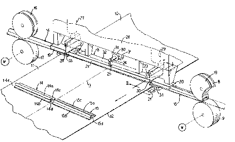
FIG. 1 is a fragmentary perspective view illustrating
mechanism for forming film with fasteners in accordance with the
principles of the present invention;
FIG. 2 is a vertical sectional view taken substantially
along line II-II of Fig. l;
FIG. 3 is a vertical sectional view similar to Fig. 2
but illustrating another form of fastener used in the practice of
the invention;
FIG. 4 is a fragmentary plan view of the center of the
film at the ends of the fastener strips;
FIG. 5 is a fragmentary vertical view showing means for
attaching the fastener strips to the film;
FIG. 6 is a fragmentary enlarged perspective view
illustrating mechanism for guiding the strips onto the film;
FIG. 7 is a fragmentary end elevational view
illustrating mechanism for permitting the film to be advanced;
FIG. 8 is a fragmentary perspective view illustrating a
further step in the folding of the film such as may occur in a
form, fill and seal machine;
FIG. 9 is a fragmentary perspective view illustrating
forming seams at each side of the film; and
FIG. 10 is a perspective view of a finished bag.
~Z5~73
DESCRIPTION OF THE PREFERRED EMBODIMENTS
As illustrated in Figs. 1 and 2, a con~inuous sheet of
thin plastic film adapted for eventually providing a bag body is
fed forwardly intermittently from a roll, not shown, by a means,
not shown, applying a controlled intermittent forward drawing
force. For example, the material may be wound on a roll and the
roll driven in rotation intermittently to pull the material 10
forwardly.
The material has lateral side edges 11 and 12 and the
longitudinal center is indicated by the broken line 13.
In accordance with the principles of the invention,
flexible rib and groove fastener elements 14 and 15 are applied
to the surface of the film. In the form shown in Fig. 1, the
member 14 is a rib member and the member 15 is a groove member,
with 14 and 15 being complementary shaped so that when pressed
together, they will interlock. The member 14 has a central rib
14a and side flanges 14b and 14c to accommodate attachment to the
surface of the film.
The strip 15 has a center groove 15a with lateral
flanges 15b and 15c for attachment to the surface of the strip.
The rib and groove strips 14 and 15 are preferably formed of a
thin thermoplastic so that they can be heat sealed to the surface
but other forms of attachment such as by adhesive may be
employed.~ Under other circumstances, attachment by heat or
impulse seal need be made only at the base area, directly under
the grooves 15d or rib 14d, or can be by means of a reactivatable
adhesive on the fastener base.
For the benefit of con~inuous operation, the film is
moved forwardly incrementally and stopped so that the fastener
strips 14 and 15 can be fed laterally across the material at a
-- 4 --
73
fastener attachment station shown wherein a suppGrting frame 26
is located. The fastener strip 14 is fed laterally from the
left, as shown in Fig. 1, by a pair of friction rolls 16 and 17
which are suitably driven to advance the material axially in a
lateral direction over the side of the sheet 10. At the opposite
side of the sheet are a pair of pinch rolls 8 and 9 which are
suitably driven to advance the fastener strip 15 laterally over
the side of the material 10. The strips are advanced until they
are adjacent the center 13, but a space at 14d may be left
between the ends of the strips to accommodate folding of the
sheet 10 about its longitudinal center 13 and to permit providing
a spot heat seal at the ends of the strips 14 and 15. Also
spaces at 14e and 15d may be left at the ends of the strips,
i.e., between the ends and the edges of the film.
The strips are advanced to the position shown in Fig. 1
with a space therebetween and cutters are brought down to sever
the strips to the desired length. The cutters are shown in the
form of knives 28 and 30 which are lowered to perform their
severing operation by supporting the piston and cylinder
assemblies 27 and 29 carried on the frame 26. The knives have
sharpened edges so that when they are brought down, they sever
the material.
For guiding the material as it is thrust laterally
across the top surface of the sheet 10, fixed outer downwardly
facing channels 19 and 20 are positioned at either end. ~hese
channels are shaped to accommodate the rib, for the channel 19
and the groove for the channel 20, with the latter generally as
shown in the end view of Fig. 2. The fixed channels have a
center continuation channel 18 which is shaped on one side, up to
its center point, so as to accommodate the fastener rib and on
lZ~73
the other side of the center point so as to accommodate the
fastener groove and has a front gate 21 which when lowere~
completes the channel groove, but which when raised releases the
fastener strips by then attached to the film so that they can be
moved forwardly as the sheet 10 is advanced. The center portion
and end portions of the channels are suspended on Yertical posts
depending from the frame 26. The channel 18 has a rear fixed
portion 32 which remains in place while the front gate 21 is
supported on hinges 22 and 23. The gate is lifted to permit the
fastener strips to be slid forwardly with movement of the sheet
10 by a bracket 25 attached to the gate 21 and which is operated
by a piston rod 24 and a cylinder 30 supported on brackets 31 on
the frame 26.
When the fastener strips are driven across on top of the
sheet 10, the rear and forward part 32 and 21 respectively of the
center channel portion 18 are positioned as shown in Figs. 1 and
2. After the strips have been driven across and cut, a vertical
reciprocal heat sealing shoe 31 moves upwardly. The shoe has a
center groove 32 so that heat is not applied to the rib 14a or
the groove 15a portion of the strips but heat is applied to the
film directly opposite the webs 14b and 14c, and the webs 15b and
15c. A suitable heating element, not shown, within the shoe 31
provides heat and the shoe is brought up into contact with the
film long enough to seal the fastener strips to the film.
Alternately, a shoe with a single centrally positioned wire that
seals the base sections of the fastener directly under the rib
and groove elements, to the film, can be used. The shoe is then
dropped, and the forward gate 21 is lifted, and the film 10 then
is moved forwardly as indicated by the arrowed line in Fig. 1.
The forward gate is then returned to its closed position. The
-- 6 --
129~3
strips, thus attached, move forwardly as shown in Fig. 1 and a
new set of strips is placed on the sheet with the strips being
attached at predetermined longitudinally spaced intervals. The
fastener can either be cut to the same width as the film, or to a
slightly shorter width, In the la~ter case, small base plates 34
are provided that ride between the film and the fastener so as to
prevent cutting of the film at that location. Whichever
arrangement is used, the sealing bars will have the same width as
the cut fastener section.
Subsequently the sheet is folded down its center 13 with
the rib and groove members interlocked in the manner that will be
explained below in connection with Figs. 8 and 9.
Figs. 3 through 7 illustrate the method and apparatus
adapted for a different form of fastener strip wherein the strip
portions from both sides of the film are identical in
construction. The strip as shown at 41 in Fig. 3 has a plurality
of ribs 41c thereon with grooves 41d therebetween. With this
form of fastener strip, a complementary strip having the
identical construction has ribs which will enter the grooves 41d,
but the strips must be slightly laterally offset from each other
so that the ribs of the other strip will confront the grooves.
The strips have webs 41a and 41b at the sides for attaching the
strips to the film 10.
As shown in Fig. 4, two strips are brought in from
opposite lateral sides of the film 10 in the manner which was
described in connection with Fig. 1. A space may be left between
the inner ends of the film as shown in Figs. 1 and 4. The
channels which guide the film are slightly offset as indicated at
42a so that ribs 41c are opposite grooves 41d. With this
relationship of the strips when the film is folded upon itself
~;~94473
along the centerline 13, the ribs will enter the grooves for the
strips to interlock.
Figs. 5, 6 and 7 indicate the guide arrangements for
guiding the strips into place. A fixed channel 46 is positioned
at the lateral edge of the film and as the strip 41 is driven
laterally across the film, it also slides into the center portion
40 of the channel. The center portion has a hinged front gate 42
which is in its lowered position, as shown in Figs. 5 and 6, when
the fastener strip is driven into place, and which is raised to
its raised posi~ion as shown in Fig. 7 when the film 10 with the
attached fastener 41 is advanced in the direction indicated by
the arrowed line in Fig. 7.
A heated sealing shoe 44 is brought up beneath the film
to seal the flanges 41a and 41b of the strip to the upper surface
of the film, or to seal the base area of the fastener.
The film thus formed is ready for processing through a
form, fill and seal machine or is suited for the manufacture of
bags and at that point may be rolled onto a roll or may be first
folded upon itself in the manner indicated in Fig. 8, for
subsequent manufacture into empty bags.
In Fig. 8 the film is folded down its longitudinal
center so that the edges 50 and 51 are brought together. Figs~ 8
and 9 illustrate one form of utilization of the film which has
now had the fasteners attached. The features of the invention
find principal use in the preparation of material for a form,
fill and seal operation. In such operation~ the film is fed
forwardly intermittently, wrapped around a mandril where contents
are placed in the wrapped film, and the edges that are brought
together from the wrapping are sealed to each other so that a
tube is formed. Thereafter, a cross seal is formed behind the
- 8 -
~g~473
contents and forming the bottom of the next bag to hold the next
charge of contents. The fasteners are in a location so that
there will be a reclosable fastener at the top of each of the
bags. After the bags have been handled so that their side seam
is formed, and they are filled, they are cut off so that
individual bags are provided each filled in the operation. Fig.
9 illustrates an alternative way of utilizing the continuous
strip of material which has had the fastener strips attached. As
illustrated in Fig. 9, the edges are sealed to each other to form
a side seam 53 for the bag by bringing a heated bar 54 against
the aligned edges. To maintain uniformity of appearance a side
seam 53a is formed, on the folded film, opposite seam 53 by
another heated bar 54a. Pressure rollers 57 and 58 are moved
across the bag to join the interlocking rib and groove members.
Alternately, upper and lower pressure bars can be used. Spot
seals 61 and 62 are formed at the ends of the strips locking them
in their relative positions so that the ribs and grooves remain
aligned. The spot seals are formed by bringing heated spot seal
members 63 and 64 down onto the material at the ends. A cross-
seam 56 is formed by a heat seal bar 55 with the cross-seams
being formed at spaced intervals to be spaced from the fastener
strips 52 to form a bag.
This completes a finished bag as illustrated at 60. The
bag 60 is completed when individual bags are cut from the length
of material formed in the manner above described.
Thus, it will be seen that there has been provided an
improved method and mechanism for making material for a bag
wherein fastener strips extend laterally across the material.
The material and the mechanism meet the objects and advantages
above set forth and provide an improved arrangement for rapid and
effective forming of bag material.
_ g _